Sinexcel Energy Freedom PWS1-1725KTL-H-NA-O User manual

I

II
Sinexcel
PWS1-1725KTL-H-NA-OBi-directional Power Conversion System
User manual
Version:V2.0
Filing Date:2023-04
Shenzhen Sinexcel Electric Co., Ltd.
All rights reserved. In case of any content change, it shall be without prior notice.
Shenzhen Sinexcel Electric Co., Ltd.
Website: http://sinexcel.us/ or www.sinexcel.com
Add: Building 6, Area 2, Baiwangxin High-tech Industrial Park, No. 1002, Songbai Road, Nanshan District,
Shenzhen
Postcode: 518055
Hotline: +86 0755-8651-1588

III
Contents
1 OVERVIEW..................................................................................................................................................................1
1.1APPLICABLE MODELS.....................................................................................................................................................1
1.2 TARGET GROUP .............................................................................................................................................................1
1.3 TERMINOLOGY................................................................................................................................................................2
2. SAFETY INSTRUCTIONS ........................................................................................................................................ 3
2.1 SAFETY INSTRUCTIONS ...................................................................................................................................... 3
2.2 IMPORTANT SAFETY INSTRUCTIONS ..............................................................................................................................3
2.3ADDITIONAL INFORMATION.............................................................................................................................................5
3 PRODUCTS.................................................................................................................................................................5
3.1 SYSTEM INTRODUCTION ................................................................................................................................................5
3.2APPEARANCE OF BI-DIRECTIONAL ENERGY STORAGE CONVERTER ..............................................................................5
3.3 DIMENSION AND WEIGHT................................................................................................................................................1
3.4 SYSTEM SCHEMATIC.......................................................................................................................................................1
3.5 SYSTEM SCHEMATIC.......................................................................................................................................................2
3.6 PCS COMPOSITION .......................................................................................................................................................5
3.7 OPERATING COMPOSITIONS ..........................................................................................................................................5
3.7.1 Switches Introduction..........................................................................................................................................5
3.8 LABELS .........................................................................................................................................................................8
3.9 HEAT DISSIPATION DESIGN.............................................................................................................................................8
4 PARAMETERS............................................................................................................................................................1
5 STORING、LIFTING AND TRANSPORTING..........................................................................................................2
5.1 TRANSPORTAND STORAGE............................................................................................................................................2
5.2 TRANSPORT ...................................................................................................................................................................4
5.3 OUT OF THE BOX INSPECTION........................................................................................................................................6
5.3.1 Unpacking.............................................................................................................................................................6
5.3.2 Inspection..............................................................................................................................................................6
6 EQUIPMENT INSTALLATION ..................................................................................................................................7
6.1 INSTALLATION REQUIREMENTS......................................................................................................................................7
6.1.1
Basic requirements............................................................................................................................................7
6.1.2
Outdoor requirements.......................................................................................................................................7
6.1.3
Foundation support requirements ...................................................................................................................8
6.1.4 Ventilation requirements.....................................................................................................................................9
6.2SITE INSTALLATION......................................................................................................................................................10
6.2.1
Wire channel design........................................................................................................................................10
6.2.2 Fixing the PCS ...................................................................................................................................................10
6.3 ELECTRICAL CONNECTION...........................................................................................................................................11
6.3.1 General safety rules ..........................................................................................................................................11
6.3.2 Installation tools .................................................................................................................................................12

IV
6.3.3 Wiring parts.........................................................................................................................................................12
6.3.4 Preparation before wiring .................................................................................................................................13
6.3.5 Cable Requirements..........................................................................................................................................13
6.3.6 Wiring Precautions.............................................................................................................................................14
6.3.7 Wiring Area Overview........................................................................................................................................15
6.3.8 DC side wiring....................................................................................................................................................16
6.3.9 AC side wiring.....................................................................................................................................................17
6.3.10 Ground Connection.........................................................................................................................................18
6.3.11 Wiring of terminal strips ..................................................................................................................................18
6.3.12 Communication................................................................................................................................................20
6.3.13 Installation checklist ........................................................................................................................................21
7 PRODUCT OPERATION.......................................................................................................................................... 22
7.1 CHECK BEFORE OPERATION ........................................................................................................................................22
7.1.1 Check cable connections..................................................................................................................................22
7.1.2 Check the PCSs.................................................................................................................................................22
7.1.3 Check the Battery/Grid Side Voltage..............................................................................................................23
7.2 POWER ONAND SHUT DOWN .......................................................................................................................................24
7.2.1 Power on.............................................................................................................................................................24
7.2.2 Shut down...........................................................................................................................................................24
7.3 OPERATING MODE........................................................................................................................................................25
7.3.1 Main Function.....................................................................................................................................................25
7.3.2 Operating status introduction...........................................................................................................................26
7.3.3 Operating State Switching................................................................................................................................27
7.4 PROTECTION FUNCTION ..............................................................................................................................................28
8 NETWORK MONITORING INTRODUCTION......................................................................................................... 29
8.2 NETWORK MONITORING INITIAL STATE DESCRIPTION ..................................................................................................29
8.3 LAN PORT CONNECTION..............................................................................................................................................30
8.4 THE OPERATION INFORMATION MENU INTRODUCTION .................................................................................................30
8.5 EVENT LOGGING MENU INTRODUCTION......................................................................................................................32
8.6 INTRODUCTION TO CONTROL &DISPATCHING MENU....................................................................................................34
8.7 INTRODUCTION TO THE SETTINGS MENU......................................................................................................................34
8.8 INTRODUCTION TO THE OPERATION STRATEGY MENU .................................................................................................36
8.9 INTRODUCTION TO LOGIN MENU..................................................................................................................................37
8.10 INTRODUCTION TO ABOUT THIS MACHINE MENU........................................................................................................38
9 TROUBLESHOOTING ............................................................................................................................................. 38
9.1 PRELIMINARY TROUBLESHOOTING...............................................................................................................................39
9.2 LED INDICATOR LIGHT DISPLAYAND TROUBLESHOOTING METHODS ..........................................................................39
9.3 COMMON FAULTS AND TROUBLESHOOTING METHODS................................................................................................40
9.4 OTHER FAULTS.............................................................................................................................................................41
10 MAINTENANCE...................................................................................................................................................... 42
10.1 SECURITIES &CAUTIONS ..........................................................................................................................................42

V
10.2 MAINTENANCE CYCLE................................................................................................................................................42
10.3 ELECTRONIC COMPONENTS REPLACEMENT..............................................................................................................44
11 APPENDIX............................................................................................................................................................... 45
11.1 QUALITYASSURANCE ................................................................................................................................................45
11.2 HMI PROTECTION PARAMETER SETTING INTRODUCTION.........................................................................................46
12 CONTACT................................................................................................................................................................ 48
INSTALLATION INFO.................................................................................................................................................. 49

1
1Overview
1.1 Applicable Models
This file applies to the following models:
PWS1-1725KTL-H series models
This section describes the product model definitions in this manual, as shown in Fig. 1-1:
Fig. 1-1 Product Model
For Example:
PWS1-1725KTL-H-NA-8M1-O:Indicates that rated capacity of 1725kW bi-directional single stage
energy storage converter without transformer, high voltage 1500V outdoor cabinet. It is 1 DC branch
and containing 8 modules with North American version.
Check the nameplate on the PCS to identify the model.
The illustrations in this file are only schematic diagram, please refer to the actual product.
1.2 Target Group
The content described in this document should only be operated by professionals.
Professionals are required to have the following skills:
Understand how the product works and how to operate it.
Understand how batteries work and how to operate them.
Be trained in and understand how to deal with hazards and risks arising from the installation and use
of electrical equipment.
Understand the installation and commissioning of electrical equipment.
Understand all applicable standard operating instructions.
Understand and comply with this manual and all safety information.

2
1.3 Terminology
Terminology
Definition
STS
Static transfer switches
AC
AC
DC
DC
BESS
Battery energy storage system
ESS
Energy storage system
EMS
Energy management system
BMS
Battery management system
PCS
Power Conversion System
SLD
Single line diagram
SOH
State of health, expressed in percentage.
SCR
Silicon controlled rectifier
DOD
Depth of discharge, expressed in percentage.
EOD
End of discharge
SOC
Remaining power, expressed in percentage.
UI
User interface
EPO
Emergency power off
SPD
Surge protective devices
3
2. Safety Instructions
2.1 Safety Instructions
Instruction
Indicates a dangerous situation which, if not avoided, will result in
death or serious injury.
Indicates a dangerous situation which, if not avoided, will result in
death or serious injury.
Indicates a dangerous situation which, if not avoided, may result in
minor or moderate injury.
Indicates that property damage will occur if not avoided.
Please note important information, best practice and advice.
Note the information used to resolve issues not related to personal
injury, equipment damage and environmental degradation.
2.2 Important Safety Instructions
This user manual for the installation and operation of the PWS1 series 1725kW bi-directional Energy
Storage Converters from Sinexcel.
Please read this user manual carefully before installation.
The bi-directional energy storage converters must be commissioned and maintained by an engineer
appointed by the manufacturer or an authorized service partner. Failure to do so may endanger
personal safety and lead to equipment failure. Damage to the equipment caused as a result is not
covered by the warranty.
Bi-directional Energy Storage Converters should not be used in any environment or application
associated with life support equipment.
This manual contains important instructions for the PWS1 series models and these instructions should
be followed when installing and maintaining the bi-directional energy storage converter.

4
Any touching of the copper strip, contacts and terminals inside the appliance that are connected to the grid
circuit may cause a fatal burn or electric shock!
Do not touch any terminals and wires connected to the grid circuit.
Take note of any instructions and safety documents regarding grid connection.
Contact with the interior of the appliance may present a risk of electric shock!
Any operation in connection with this appliance must be carried out by qualified personnel.
Please note the safety precautions listed in the safety instructions and installation documentation.
Please take note of the safety precautions listed in the operating and installation manuals and other
documentation.
Massive power leakage
Before connecting the input power, ensure that the earth is securely grounded.
The appliance must be earthed in accordance with local electrical codes.
When the battery is connected to a bi-directional energy storage converter, DC voltage may be present at
the input port. Please take care during operation or check the battery system user manual.
Do not touch live parts within 15 minutes of power failure!
Dangerous energy is stored in the internal capacitors, so do not touch the terminals, contacts, copper strip,
etc. for 15 minutes after disconnecting the appliance from all power sources.
All internal maintenance and servicing of the equipment should be carried out by trained personnel. Internal
components that require the use of tools to open cannot be maintained by the user.
Please read this user manual before operation.
5
2.3 Additional Information
For further details please click:www.sinexcel.us
3 Products
3.1 System Introduction
PWS1-1725KTL-H series bi-directional energy storage converter (PCS) is a conversion device between
the grid and the battery, which can charge and discharge the battery. It can invert the DC power from the
battery into AC power that can be connected to the grid and rectify the AC power from the grid into DC
power that can be charged into the battery. Bidirectional energy storage converters can be used in on-grid
mode or off-grid mode.
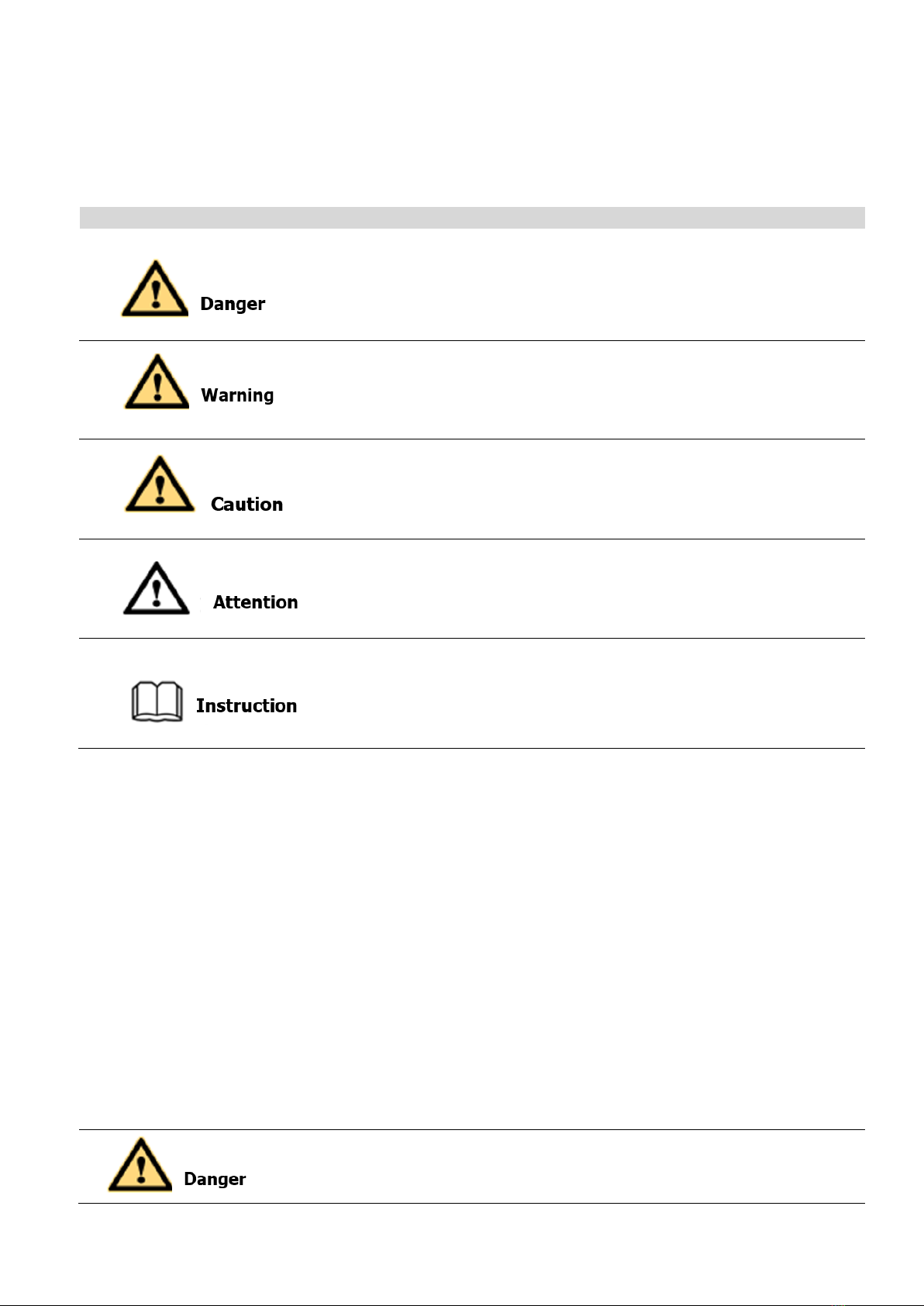
3.2 Appearance of bi-directional energy storage converter
Fig. 3-1 Appearance of Bidirectional Energy Storage Converter
Position
Description
Instruction
A
Power indicator
Control circuit power indicator
B
RUN indicator
Always on when the converter is running
normally
C
FAULT indicator
Always on when there is a fault, blinking when
there is an alarm
D
Emergency stop knob
Press in case of emergency to disconnect AC
and DC power immediately
A
B
C
D
E
6
E
AUX knob
Control the inverter aux power*
*The knob is used to control the power supply mode of the auxiliary power supply. When the AUX knob is rotated to ON, the rack auxiliary
source supplies power to the control box, and the control box supplies power to the module communication. When the control box is powered
on, it can control the DC electric operation switch and the AC electric operation breaker to close.When theAUX knob is rotated to OFF, the DC
switch andAC circuit breaker work normally, and the auxiliary power supply of the control box is provided by the module.
Fig. 3-2 Front view for PCS-AC module
LED designation
Description
Instruction
1
DIP switch
Address
2
Fault indicator light
Red
3
Normal indicator light
Green
4
Communication cable socket
5
Handle
Can’t bearing too much weight
6
24VDC Power supply socket
7
220VAC Power supply socket
8
The drawer of Fan
1
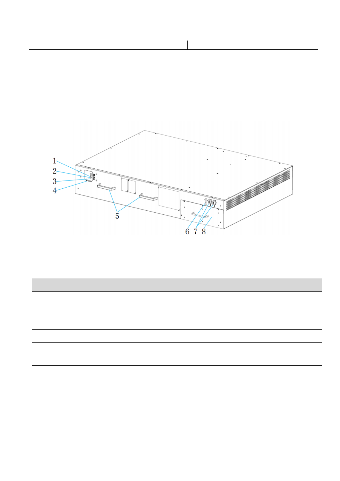
3.3 Dimension and weight
The dimension of PWS1-1725KTL-H series energy storage converters are marked as shown in Fig. 3-3.
The net weight of the product is about 2390kg, and the specific weight is subject to the actual nominal
weight.
Fig. 3-3 PWS1-1725KTL-H Series Energy Storage Converter External Dimensions
3.4 System schematic
The PWS1-1725KTL-H bidirectional energy storage converter consists of multipleAC modules. The
equipment is equipped with SPD protectors,AC and DC switches and auxiliary power distribution units.
The schematic diagram of the main circuit inside the energy storage converter is shown in Fig. 3-4. It uses
a three-phase three-level topology to realize rectification and inversion. The battery pack interface can be
directly connected to the battery, and the AC interface can be connected to the grid orAC load after the
isolation transformer or step-up transformer.
2160
1300
2200

2
DC SPD
DC
Disconnect
Switch
DC isolation
fuse
DC
EMC
AC Filter AC
EMC AC
Circuit
Breaker
AC SPD
A
B
C
BAT+
BAT-
Unit1
Unit8
Fig. 3-4 Schematic diagram of energy storage converter topology
3.5 System schematic
PWS1-1725KTL-H Bi-directional Storage Inverter (PCS) is composed of 8 PCS-AC modules. The modules
identify master-slave systems through the DIP switch dial-up codes on the panel. #1 is a master system,
while other modules track the master system. The Bi-directional Storage Inverter (PCS) cabinet is
equipped with SPD protector, AC/DC breaker and distribution units. If on/off-grid switching is to be
achieved, extra power distribution unit needs to be added. Fig.3-5,3-6,3-7,3-8 are topological graphs for its
composition and structure.
Fig. 3-5 Topological graph for Bi-directional Storage Inverter (PCS) with 1 branch input

3
Fig. 3-6 Topological graph for Bi-directional Storage Inverter (PCS) with 8 branch input
Fig. 3-7 Topological graph for Bi-directional Storage Inverter (PCS) with 2 branch input

4
Fig. 3-8 Topological graph for Bi-directional Storage Inverter (PCS) with 4 branch input
Both models have identical mechanical and electrical construction except composed of different sets of
PCS-AC modules and rating:
PWS1-1725KTL-H series is composed of 8 sets of PCS-AC modules, the DC branches can be selected of
1, 2, 4 or 8 by different number of DC switches.
Serial No.
Item
Quantity
Remark
1
Cabinet
set
The cabinet is equipped with distribution
2
PCS-AC module
8 set(s)
3
Power Management
Unit
1 set
5
4
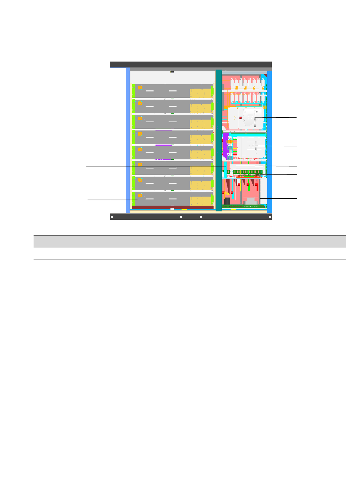
3.6 PCS Composition
Fig.3-9 Visible Components of the PCS
Position
Description
Instruction
1
PCS-AC (1~8 module(s))
215kW 1 set
2
Battery DC Switch
1, 2, 4 or 8 set of DC Switch
3
AC Switch
4
AUX Power box
5
U2 control PCBA
6
Wiring terminal
3.7 Operating Compositions
3.7.1 Switches Introduction
3.7.1.1 AC switch
TheAC disconnection unit disconnects the PCS from the Grid.
1
2
3
5
6
6

6
CLOSED
OFF
Fig. 3-10 Switch positions of the AC disconnection unit
Position
Description
Instruction
CLOSED
Switch In On position
The AC connection
unit is closed.
OPEN
Switch In OFF position
The AC disconnection
unit is open.
CHARGED
Energy storage completion
DISCHARGED
Unstored energy
3.7.1.2 DC switch
The DC disconnection unit disconnects the PCS from the Battery module arrays.
Fig. 3-11 Switch positions of the DC disconnection unit
OPEN
DISCHARGED
CHARGED
Discharged
Charged
ON

7
6
4
9
10
11
8
2
1
Position
Description
Instruction
ON
Switch In On position
The DC connection
unit is closed.
OFF
Switch In OFF position
The DC disconnection
unit is open.
Charged
Energy storage completion
Discharged
Unstored energy
3.7.1.3 AUX power supply switch & Fan power switch
AUX power supply can be the redundancy power supply through the AC Switch inside the PCS
cabinet.
Fig.3-12 Visible Components of the PCS
Position
Description
Instruction
1
QS1
AUX power supply AC switch
2
QF1
AUX external power supply AC switch
3
FU4
AC fuse
4
QS2
Fan power supply switch
5
QF2
Fan external power supply switch
6
FU3
DC fuse
7
QS3
AUX power supply DC switch
7
5
3

8
8
FU1
AC fuse
9
FV1
AC SPD
10
FU2
DC fuse
11
FV2
DC SPD
3.8 Labels
No.
Label
Instruction
1
Label-Dot label-L1 phase
2
Label-Dot label-L2 phase
3
Label-Dot label-L3 phase
4
Label-Dot label-Positive electrode
5
Label-Dot label-Negative electrode
6
Label-Dot label-Grounding
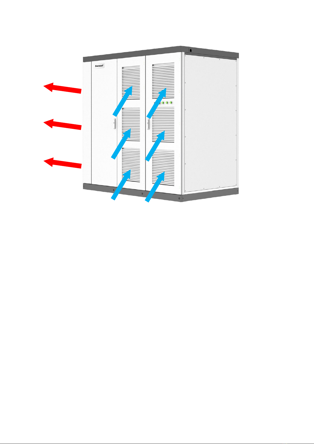
3.9 Heat dissipation design
PWS1-1725KTL-H-NA-O series energy storage converter is NEMA3R outdoor unit, the whole adopts the
structure design of air inlet on the right side door panel and air outlet on the left side door. The air outside
the cabinet enters through the air inlet hole of the front door panel of the energy storage converter, and the
hot air is exhausted through the air duct on the left side door of the PCS. The ventilation design is shown in
Fig. 3-13.
L1
DC+
L3
L2
DC-
9
Fig. 3-13 PWS1-1725KTL-H series energy storage converter ventilation design
Table of contents
Other Sinexcel Storage manuals


Popular Storage manuals by other brands


Synology
Synology RackStation RS2414RP+ Quick installation guide

Buffalo
Buffalo JustStore Portable HD-PVU2 user manual

ASUSTOR
ASUSTOR AS64 Series installation guide

Seagate
Seagate MARATHON 1680 product manual

Monument
Monument 312 Owner's Manual & Installation Instructions

kupper
kupper 70190 Assembly instruction


