Sinexcel Energy Freedom S90 User manual
S90 Outdoor Cabinet
Manual

Sinexcel Co.
S90 Energy Storage Outdoor All-in-One Cabinet User's Manual
Version: 1.0
Shenzhen Sinexcel Electric Co.
All rights reserved. Contents are subject to change without notice.
Shenzhen Sinexcel Electric Co.
Company website: www.sinexcel.com
Address:Block 6, Block 2, Baiwangxin Hi-Tech Industrial Park, No.1002 Songbai Road,
Nanshan District, Shenzhen, China
Contact:0755-8651-1588

1
CONTENT
1 OVERVIEW............................................................................................................................................... 4
1.1APPLICABLE MODELS ..................................................................................................................................4
1.2 TARGET GROUP...........................................................................................................................................4
1.3 TERMINOLOGY.............................................................................................................................................4
2 SAFETY INSTRUCTIONS....................................................................................................................... 5
2.1 SYMBOLS.....................................................................................................................................................5
2.2 IMPORTANT SAFETY INSTRUCTIONS ...........................................................................................................5
2.3ADDITIONAL INFORMATION..........................................................................................................................6
3 PRODUCTS.............................................................................................................................................. 7
3.1 SYSTEM INTRODUCTION..............................................................................................................................7
3.2APPEARANCE OF THE INTEGRATED ENERGY STORAGE CABINET..............................................................7
3.3 DIMENSION AND WEIGHT............................................................................................................................7
3.4 SYSTEM SCHEMATIC DIAGRAM...................................................................................................................8
3.5 HEAT DISSIPATION DESIGN.........................................................................................................................8
4 TECHNICAL SPECIFICATIONS............................................................................................................. 9
5 STORAGE, HANDLING AND TRANSPORT....................................................................................... 11
5.1 TRANSPORTAND STORAGE .......................................................................................................................11
5.2 TRANSPORT...............................................................................................................................................13
5.3 UNPACKING INSPECTION...........................................................................................................................14
5.3.1 Unpacking........................................................................................................................................14
5.3.2 Inspection.........................................................................................................................................15
6 EQUIPMENT INSTALLATION............................................................................................................... 16
6.1 INSTALLATION REQUIREMENTS..................................................................................................................16
6.1.1 Basic requirements.........................................................................................................................16
6.1.2 Outdoor requirements ....................................................................................................................16
6.1.3 Foundation support requirements ................................................................................................16
6.1.4 Space requirements .......................................................................................................................17
6.1.5 Ventilation requirements................................................................................................................18
6.2 SITE INSTALLATION....................................................................................................................................19
6.2.1 Wire channel design.......................................................................................................................19
6.2.2 Fixation of Energy Storage Integrated Cabinet ..........................................................................19
6.3 ELECTRICAL CONNECTION ........................................................................................................................20
6.3.1 General safety rules .......................................................................................................................20
6.3.2 Installation tools ..............................................................................................................................21
6.3.3 Wiring parts......................................................................................................................................21
6.3.4 Preparation before wiring...............................................................................................................22

2
6.3.5 Cable requirements ........................................................................................................................22
6.3.6 Wiring precautions..........................................................................................................................23
6.3.7 Wiring area overview......................................................................................................................24
6.3.8 DC Side Wiring................................................................................................................................28
6.3.9 AC Measurement Wiring................................................................................................................28
6.3.10 Ground Connection......................................................................................................................29
6.3.11 Communication Interface.............................................................................................................30
6.3.12 Installation Checklist.....................................................................................................................31
7 PRODUCT OPERATION ....................................................................................................................... 32
7.1 CHECK BEFORE OPERATION......................................................................................................................32
7.1.1 Check cable connections...............................................................................................................32
7.1.2 Check the Energy Storage Converter..........................................................................................32
7.1.3 Check the Battery/Grid Side Voltage ...........................................................................................33
7.2 OPERATION OF THE EQUIPMENT ...............................................................................................................34
7.2.1 Power-up operation ........................................................................................................................34
8 S90-GATEWAY CONFIGURATION INSTRUCTIONS......................................................................... 35
8.1 PRE-CONFIGURATION PREPARATION........................................................................................................35
8.2 EMS SYSTEM INTRODUCTION..................................................................................................................37
8.2.1 Dashboard .......................................................................................................................................39
8.2.2 PCS...................................................................................................................................................40
8.2.3 EMS..................................................................................................................................................40
8.2.4 History...............................................................................................................................................41
8.2.5 Tools..................................................................................................................................................41
9 S90 OUTDOOR CABINET FFS............................................................................................................ 43
10 TROUBLESHOOTING......................................................................................................................... 44
10.1 PRE-EXAMINATION ..................................................................................................................................45
10.2 LED INDICATORS AND TROUBLESHOOTING METHODS............................................................................45
10.3 COMMON FAULTS AND HANDLING METHODS...........................................................................................46
10.3.1 Energy storage converter-related faults....................................................................................46
10.3.2 Air conditioning system related faults....................................................................................... 61
10.4 OTHER FAULTS........................................................................................................................................65
11 MAINTENANCE ................................................................................................................................... 65
11.1 SECURITIES &CAUTIONS........................................................................................................................66
11.2 MAINTENANCE WORK AND CYCLE ...........................................................................................................67
11.3 COMPONENT INSPECTION.......................................................................................................................68
11.3.1 Replacing the dust jacket.............................................................................................................68
11.3.2 Check and maintain the fire extinguishing system...................................................................68
11.3.3 Check vents...................................................................................................................................69

3
11.3.4 Maintaining the Fire Hose............................................................................................................70
11.4AIR CONDITIONER MAINTENANCE...........................................................................................................70
11.4.1 Maintenance of the air conditioner module structure...............................................................70
11.4.2 Check Normal operation............................................................................................................. 71
11.5 COMMON FAULTS AND TROUBLESHOOTING MEASURES.........................................................................72
12 APPENDIX ............................................................................................................................................ 74
12.1 QUALITYASSURANCE...............................................................................................................................74
13 CONTACT............................................................................................................................................. 74

4
1 Overview
1.1 Applicable models
This document applies to the following equipment models:
S90 Outdoor Cabinet BESS
This section describes the product model definitions in this instruction manual,
As shown in Figure 1-1.
1.1 Product Model Definition
1.2 Target group
The content described in this document should only be operated by professionals.
Professionals must have the following skills.
Understand how the product works and how to operate it
Understand how batteries work and how to operate them
Trained and understand how to deal with hazards and risks that arise during the installation
and use of electrical equipment
Understand the installation and commissioning of electrical equipment and devices
Understand all applicable standard operating instructions
Understand and comply with this manual and all safety information
1.3 Terminology
Name
Definition
STS
Static Transfer Switch
AC
AC
DC
DC
BESS
Battery Energy Storage System
ESS
Energy Storage System
EMS
Energy Management System
BMS
Battery Management System
PCS
Bidirectional Energy Storage Converter
SLD
Single Line Diagram
SOH
Battery health status, expressed as a percentage
SCR
Thyristor rectifier
DOD
Depth of discharge, expressed as a percentage
EOD
Discharge cutoff
SOC
Remaining power, expressed as a percentage
UI
User Interface
EPO
Emergency Power Off
SPD
Surge Protector

5
2 Safety instructions
2.1 Symbols
Logo
Explanatory notes
Indicates a dangerous situation that, if not avoided, will result in
death or serious injury.
Indicates a dangerous situation that, if not avoided, will result in
death or serious injury.
Indicates a hazardous situation that, if not avoided, could result in
minor or moderate injury.
Indicates that property damage will occur if not avoided.
Attention to important information, best practices and
recommendations.
Attention is drawn to information used to resolve issues unrelated
to personal injury, equipment damage and environmental
degradation.
2.2 Important Safety Instructions
This user manual is about the installation and operation of the SES-90K outdoor cabinet
from Sinexcel.
Please read this user's manual carefully before installation.
The S90 outdoor cabinet must be commissioned and maintained by an engineer designated
by the manufacturer or an authorized service partner. Failure to do so may endanger
personal safety and result in equipment failure. Damage to the equipment caused as a result
is not covered by the warranty.
The S90 Outdoor Cabinet should not be used in any environment or application related to life
support equipment.
This manual contains important instructions for the SES-90K series models and should be
followed when installing and maintaining the Energy Storage Outdoor Cabinet.
Any touching of the copper strip, contacts, or terminals connected to the grid circuit inside the unit may
result in a fatal burn or electric shock!
Do not touch any terminals and wires connected to the grid circuit.
Pay attention to any instructions and safety documents regarding grid connection.

6
There may be a risk of electric shock inside the equipment!
Any operation related to this equipment must be carried out by qualified personnel.
Please note the safety precautions listed in the safety instructions and installation documentation.
Please note the safety precautions listed in the operating and installation manuals and other
documentation.
Large amount of leakage current
Before connecting input power, make sure grounding is reliable.
The equipment must be grounded in accordance with local electrical codes.
When the battery is connected to the energy storage outdoor cabinet, DC voltage may be present at
the input port. Be aware or check the battery system user manual during operation.
Do not touch energized parts within 15 minutes of power failure!
Dangerous energy is stored in the internal capacitors, so do not touch the terminals, contacts, copper
strips, etc. of the equipment for 15 minutes after disconnecting all power sources.
All internal maintenance and servicing of the equipment should be performed by trained personnel.
Internal components that require tools to open cannot be maintained by the user.
Please read this user manual before operation.
2.3 Additional Information
For additional details, please click: www.sinexcel.com.

7
3 Products
3.1 System Introduction
S90 energy storage cabinet is an all-in-one outdoor cabinet system containing bi-directional
energy storage inverter module, DCDC PV optimizer module, STS intelligent switching
module, battery system, transformer, fire protection system, air conditioning system,
auxiliary source power supply and other energy storage batteries.
The two-way energy storage converter can charge and discharge the built-in battery system,
the DCDC PV optimizer module can access the PV system to store PV power to the battery
or power the load through the energy storage converter, and the STS intelligent switching
module can realize fast and intelligent automatic switching to and from the grid.
3.2 Appearance of the Integrated Energy Storage Cabinet
Figure 3.1 Appearance of the energy storage all-in-one cabinet
Location
Name
Description
A
Power indicator
Control circuit power supply indicator.
B
Run indicator
Always on when the outdoor cabinet is in
normal operation.
C
Fault Indicator
Always on when there is a fault, flashing
when there is an alarm.
D
Emergency stop knob
Press in case of emergency to disconnect
AC and DC power immediately.
3.3 Dimension and Weight
The dimensions of SES-90K energy storage outdoor cabinet are marked as shown in Figure 3.2.
The net weight of the product is about 1800kg, and the specific weight is subject to the actual
nominal weight.

8
Figure 3.2 External dimensions of the energy storage integrated cabinet
3.4 System Schematic Diagram
S90 energy storage outdoor cabinet contains PCS, DC/DC module,ATS, battery
pack, SPD protector, GATEWAY and auxiliary power distribution unit, etc. Up to 3 groups
of DC/AC module, 3 groups of DC/DC module and 1 ATS are optional. The PCS AC
measurement can be connected to the grid or AC load through the isolation transformer,
and the PV interface can be directly connected to the PV system.
Figure 3.3 Topology diagram of the integrated energy storage cabinet
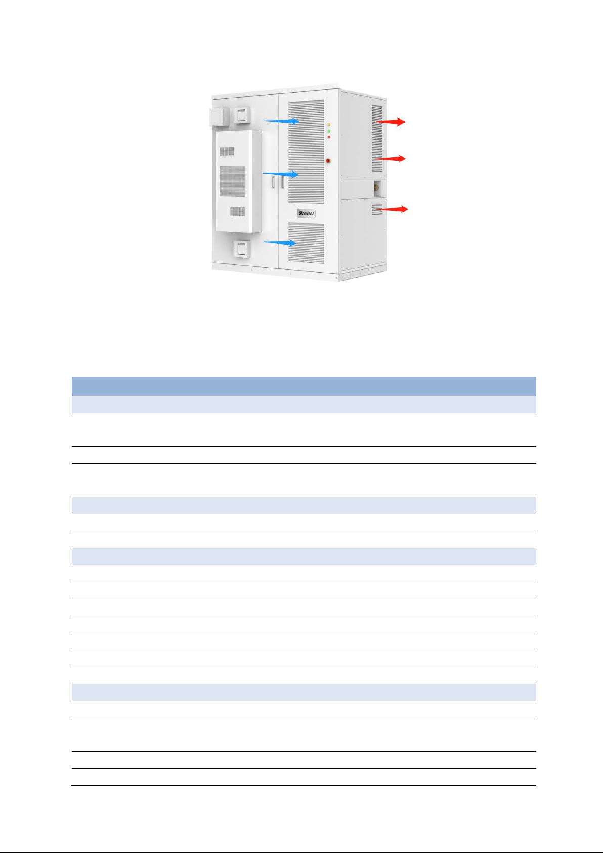
3.5 Heat Dissipation Design
The S90 Outdoor Cabinet BESS is IP54 outdoor machine, the whole adopts the structure design
of forward air and side air outlet, the outdoor air enters through the front air inlet window of the
energy storage all-in-one machine, the hot air is discharged through the exhaust air outlet at the
bottom, the fan exhaust is 1880m³/h, the ventilation design is shown in Figure 3.4.
9
Figure 3.4 Ventilation design of energy storage outdoor cabinet
4 Technical Specifications
Technical parameters table
Model
S90 Outdoor Cabinet BESS
DC Side
Charging and Discharging
voltage range
200V-750V (350V-750V @full load)
(Due to the electrical design different with the 30P module)
Rated Power
30kW*n (1~3)
Maximum Charging and
Discharging Current
90A*n(1~3)
DC Bus Side
PV Voltage Range
250V-830V
Maximum Input Current
65A*n (1~3)
AC Side
Rated Output Power
30kVA*n (1~3)
Maximum Apparent Power
33kVA*n (1~3)
Maximum Active Power
30kW*n (1~3)
AC Voltage Grid-tied
400V(-15%~15%)3P4W+PE/480V(-15%~15%)3P3W+PE
AC Voltage Off-grid
400V(-20%~20%)3P3W+PE/480V(-5%~5%)3P3W+PE
AC Frequency
50Hz/60Hz(-2.5Hz~2.5Hz)
THDi
<3%
General Specification
Dimension(W*H*D)
2100*1300*2450mm
Cooling
Forced air cooling for power electronics
5kW Air-conditioned for battery system (pre-installed)
Enclosure
NEMA 3R/IP54
Weight
1800kg (without battery)

10
Operation Altitude
3000m (>2000m derating)
Operation Temperature
-20℃~55℃(De-rating over 45°C)
Operation Humidity
0-95% (No condensing)
Noise
70dB
Power Converter Compatibility
Model
Sinexcel PWS2-30M-EX
PWS2-30P-EX/NA
Max PCS units
3
AC power range
30kW (400 Or 800Vac & 350-750Vdc) *n units (n=1,2,3)
15kW (400 Or 480Vac & 150-350Vdc) *n units (n=1,2,3)
DCDC Charger Compatibility
Model
Sinexcel PDS1-45K
Max DCDC units
3
PV Input Power
45kW*n units (n=1,2,3)
PV Input Voltage Range
200V-810V
Battery Compatibility
Battery string voltage range
150-750Vdc
Max. battery pack width
<1080mm /42.5 in
<520mm /20.5 in
One column
Two columns
Max. battery pack depth
915mm / 36 in
Max. battery rack height
1880mm / 74 in
Battery capacity
Up to 240kWh
Auto-switching Compatibility
Model
PWD-100K
Switching Time
Active Switching: Seamless
Passive Switching: 30ms
Communication
Communication Port
CAN/RS485/Ethernet
Communication Protocol
Modbus TCP/RTU,IEC104
BMS Access
Support
Optional Components
Fire Fighting System
Sensor tube, with the agent of NOVEC 1230 or FM200
or water
Built-in transformer
400V/400Vac or 480V/480Vac, 100kVA
Built-in gateway
For Peak-shaving, demand charge management or back-up
power supply.
Aux power
220V single phase built-in, up to 5kw transformer
120V built-in, up to 3kW
Salt spray prevention
Optional Salt spray prevention version
with special coating and filter
Compliance
UL9540
11
5 Storage, Handling and Transport
5.1 Transportand Storage
During transportation, in order to ensure that the energy storage outdoor cabinet is in a
better protected state, please choose to transport with packaging as far as possible, and
transport according to the indication of various markings on the packaging, the illustration of
packaging markings is shown in Table 5-1.
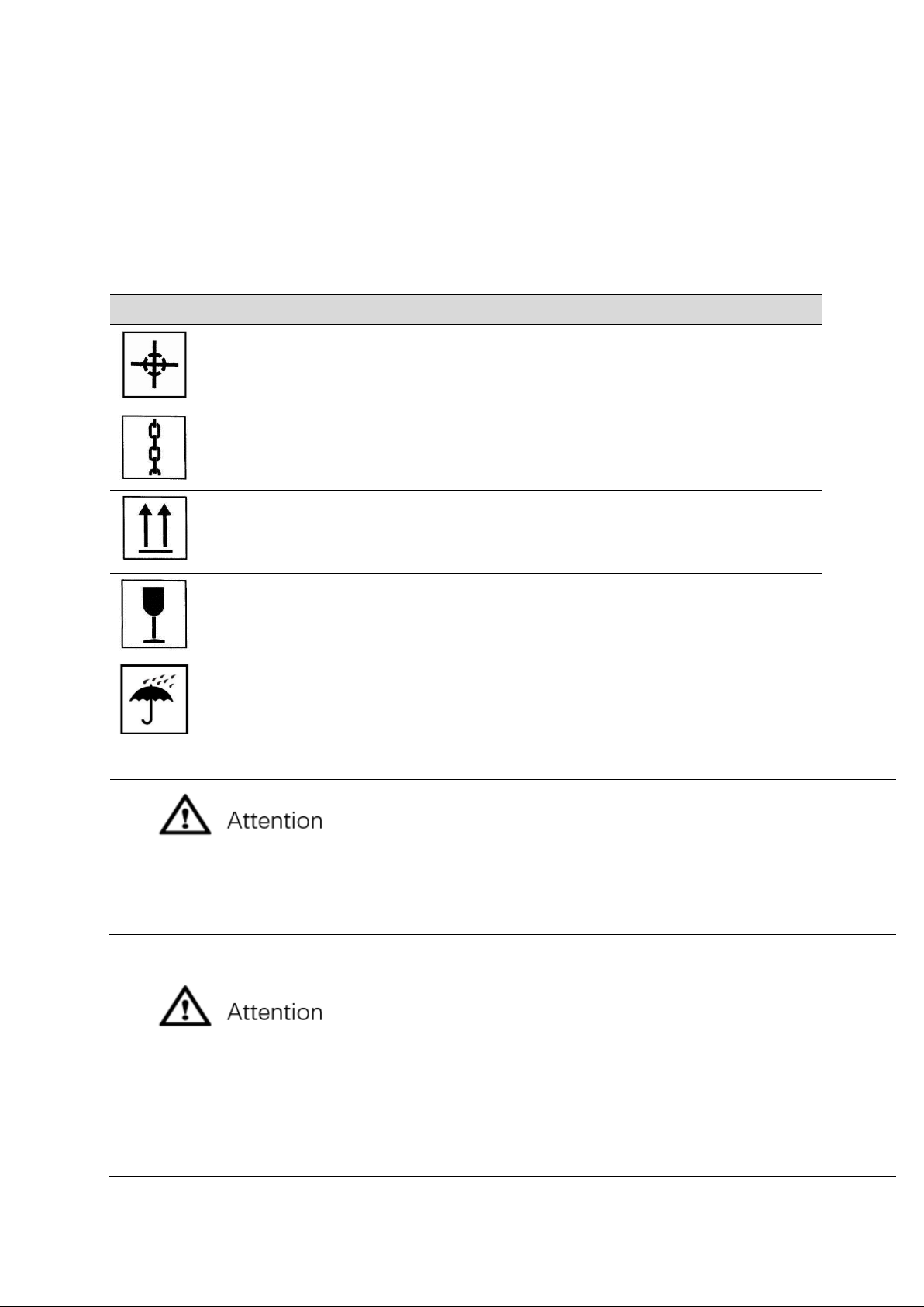
Table 5-1 package logo description
Icon
Description
Center of gravity marking, indicating where the center of gravity of the
energy storage outdoor cabinet is located
Lifting sign, indicating the position of chain or rope when lifting the
energy storage outdoor cabinet
Upward marking, indicating the way to place the energy storage
outdoor cabinet when handling and placing, forbidden to invert, place
horizontally or tilt.
Lightly placed signs, transport and placement process should avoid
violent friction or collision.
Fear of moisture signs, transportation and storage process should
avoid energy storage outdoor cabinets suffer from rain or moisture.
As the location of the center of gravity is not the mechanical center of the energy storage outdoor
cabinet, in the transportation process, must always pay attention to the center of gravity mark on the
packaging box.
Whether or not the outdoor cabinet with external packaging, moving process is strictly prohibited to tilt
angle > 5 °. Due to its volume and weight, tilt angle is too large may make the equipment backwards,
resulting in casualties or equipment damage.
In the process of moving should avoid physical impact on the equipment, such as suddenly put down,
lift, etc.
12
Avoid rain or bad weather conditions for the transport of energy storage outdoor cabinets, if
unavoidable, please take the necessary protective measures.
If on-site installation is not carried out immediately after the completion of delivery and
acceptance work, the energy storage outdoor cabinet with external packaging should be stored in
a ventilated, dry and tidy indoor environment. At the same time, the following aspects should be
noted.
⚫Restore the package to the state at the time of receipt, and the desiccant inside the
package must be retained.
⚫Storage floor is flat and sufficient to carry the weight of the energy storage outdoor
cabinet with outer packaging.
⚫Equipment storage needs to pay attention to ventilation and moisture, storage
environment is strictly prohibited to have standing water.
⚫Storage environment temperature requirements -40 ℃~ +60 ℃, storage environment
relative humidity requirements 0 ~ 100%, non-condensing.
⚫Pay attention to deal with the harsh environment around, such as sudden cold, sudden
heat, collision, etc., so as not to cause damage to the equipment.
⚫Regular inspection, at least once a week. Check whether the packaging is intact to avoid
insect and rodent bites, and the outer packaging should be replaced immediately if it is
broken.
⚫If the storage time exceeds six months, the package should be opened for inspection
and repackaged after replacing the desiccant.
Energy storage outdoor cabinet for a whole device, transportation or storage are not allowed to break it
down. Equipment failure caused by modifications not authorized by Sinexcel Electric is not covered by
the warranty.
When transporting and storing the equipment, stacking is strictly prohibited and no other items are
allowed to be stacked on top of it.

13
The equipment should be transported and stored in an environment free of corrosive gases, high
temperature and heat sources, non-dusty, and in accordance with fire protection requirements. Storage
without packaging is strictly prohibited.
5.2 Transport
Short distance handling not removed from the transport packaging box of energy storage
outdoor cabinet is recommended to preferably use forklift to move the entire box, moving the box
should pay attention to the center of gravity mark and lifting mark position, and ensure that the
transport tools have sufficient bearing capacity, the use of lifting is strictly prohibited.
Moving energy storage outdoor cabinets without boxes are usually used in the vicinity of the
equipment installation, and it is recommended that they be operated preferably with a forklift,
which requires the removal of the bottom baffle.
1) Forklift movement (preferred)
Using forklift to carry the energy storage outdoor cabinet is the standard way to move. The
center of gravity of the converter should fall between the two forks of the forklift when carrying,
and be pre-inserted to ensure that it will not tilt after lifting. As shown in Figure 5-1, the length of
forklift forks should not be less than 2.1m.
When using forklift to fork up, put down and move the energy storage outdoor cabinet, make
sure that it is slow and smooth, and the energy storage outdoor cabinet must be placed on a solid
and flat ground.
In the whole process of using forklift for operation, the forklift safety operation specification
must be strictly observed. Due to the large size of the energy storage outdoor cabinet, it may
block the driver's view, and there should be supporting personnel to cooperate.
5.2 Forklift diagram
2) Pallet truck movement
The use of pallet trucks to move the energy storage outdoor cabinet is only applicable to the
case where the transportation route is relatively smooth. The center of gravity of the outdoor
cabinet should fall between the two forks of the forklift when it is moved, and be pre-inserted to
ensure that it will not be tilted after being lifted. As shown in Figure 5-2, the length of forklift forks
shall not be less than 2.1m, the inner distance between the two fork arms of pallet truck shall not
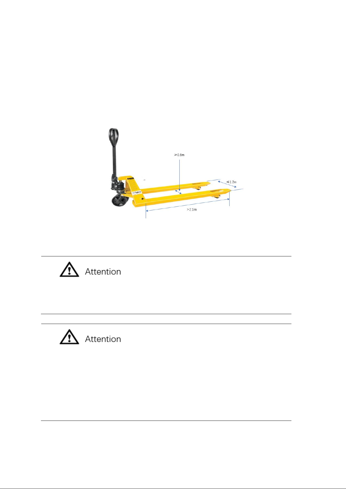
14
be less than 0.8m and the outer distance shall not be more than 1.2m, and the load-bearing
capacity of pallet truck needs to be >1800kg.
In the process of using forklift to fork up, put down and move the energy storage outdoor
cabinet, make sure that it is slow and smooth, and the energy storage outdoor cabinet must be
placed on a solid, flat ground.
In the whole process of using forklift for operation, the relevant safety operation specification
must be strictly observed. Due to the large size of the energy storage outdoor cabinet, the
operator's view may be blocked, there should be support personnel to cooperate.
Diagram of pallet truck
The bottom baffle of the energy storage outdoor cabinet must be removed before
using forklift or pallet truck for mobile operation, otherwise the bottom baffle will be
damaged.
Regardless of the method chosen to move the energy storage outdoor cabinet, it must be
ensured that:
⚫The position of its center of gravity must always be noted.
⚫Its size and weight must always be taken into account.
⚫Operator safety must be ensured at all times.
Take the necessary auxiliary measures to ensure that the equipment is delivered to
the installation site in good condition.
5.3 Unpacking Inspection
5.3.1 Unpacking
After transporting the energy storage outdoor cabinet to the vicinity of the installation site, the

15
transport packing box needs to be dismantled, and the dismantling steps are as follows.
①Removing the top panel of the packing box.
②Disassemble the wooden side panels of the packing box.
③Remove the shielding material from the box.
④Remove the anchoring components that secure the energy storage outdoor cabinet to
the shipping wood tray.
After removing the anchoring parts between the energy storage outdoor cabinet and
the transport wood tray, it is strictly forbidden to carry the energy storage outdoor
cabinet through the wood tray again.
5.3.2 Inspection
Before leaving the factory, the energy storage outdoor cabinet has been checked by
Sinexcel Electric staff themselves and packed firmly. Nevertheless, after the removal of energy
storage transport packaging still need to inspect the following.
Check whether the quantity of each item in the packing list is consistent with the physical
object.
Check whether the nameplate data of the product matches with the ordering contract, such
as product type, rated capacity, voltage level, etc..
Check whether the factory documents and accessories are complete.
Check whether the appearance of the energy storage outdoor cabinet is consistent with the
description in this manual.
Check whether the energy storage outdoor cabinet has deformation, paint loss and loose
parts.
The packing list of energy storage outdoor cabinet is shown in Table 5-2.
Table 5-2 Packing list
Serial
number
Name
Quantity
1
SES-90K energy storage outdoor cabinet (including cabinet door
key and related accessories)
1 set
2
SES-90K series user manual
1 copy
3
Equipment wiring diagram
1 copy
4
Product Certificate of Conformity
1 copy
5
Inspection report
1 copy
6
Warranty card
1 copy

16
Only the inspection is correct and complete without damage to the energy storage outdoor cabinet can
be installed and commissioned, check the process, once the problem is found, please contact with the
transporter or Sinexcel Electric in a timely manner.
6 Equipment installation
6.1 Installation requirements
6.1.1 Basic requirements
SES-90 energy storage all-in-one cabinet has IP55 protection level and can be installed
outdoors, but it should not be placed in high humidity environment for a long time. Due to the
noise generated during operation, the energy storage inverter should be installed in a location
away from residential areas and the installation location should be free from corrosive and
combustible gases.
To ensure the safe and efficient operation of the energy storage cabinet, it is important to
observe the following when selecting the installation environment.
⚫The energy storage integrated cabinet must be mounted on a suitable concrete support
with a refractory surface, and the converter inlet and outlet must not be obscured.
⚫The installation ground is dry and flat, no water accumulation, the ground level does not
shake, and it can completely carry the weight of the energy storage all-in-one cabinet.
⚫Installation site ambient temperature range: -40℃~+60℃; relative humidity range:
0~100%, non-condensing.
⚫Energy storage integrated cabinet grounding resistance <4Ω.
⚫Cabinet should be installed in a location that ensures easy viewing of the LED indicators
and operation of the LCD touch screen.
⚫If the machine is placed directly outdoors, it is recommended to take the necessary
shading measures for the machine to avoid the machine temperature rising due to direct
sunlight, causing the machine to run at reduced capacity.
6.1.2 Outdoor requirements
SES-90 is capable of operating within an ambient temperature of -40°C to 60°C.
When the temperature is higher than 45℃the machine will run at a reduced rate. When the
temperature is lower than -20℃, it needs to warm up first before high power operation.
The sunlight irradiation intensity should be ≤1200W/m^2, and it is recommended that the
converter installed outdoors should take the necessary shading measures.
6.1.3 Foundation support requirements
Since the electrical compartment of the energy storage all-in-one cabinet is side air outlet
and the front air outlet of the battery compartment, it is recommended to ensure at least 1m air
ducts on the side and front when installing the all-in-one cabinet.

17
Due to the installation of wall-mounted air conditioning in the battery compartment door of
the integrated cabinet, 350mm space is reserved on the side of the battery compartment to
ensure the normal opening of the door.
The energy storage cabinet needs to be installed on a concrete foundation or a structure
supported by steel channel with a surface of flame retardant material. Must ensure the foundation
is flat and solid, safe and reliable, and has sufficient bearing capacity, strictly forbidden to install
on the surface of the foundation with depression or tilt.
When building the foundation, according to the overall design of the power station and the
location of the cables in and out of the bottom of the energy storage cabinet, the cable trench
should be preset.
Pre-opening holes are required on the base, and the size of the opening holes must be
exactly the same as the positioning holes of the base of the energy storage cabinet, in order to
firmly connect the energy storage cabinet with the foundation.
As shown in Figure 6-1, the base of the energy storage cabinet is equipped with eight
35mm*20mm positioning waist holes, and it is recommended to use M16*45 bolts to fasten the
converter base to the foundation.
Figure 6-1 Bottom view of SES-90 cabinet
6.1.4 Space requirements
As shown in Figure 6-2, when installing the energy storage all-in-one cabinet, sufficient
distance must be retained between it and the wall and other equipment in order to meet the
requirements for the narrowest maintenance access, evacuation routes and ventilation. This
subsection requires the minimum space requirement for the normal operation of the energy
storage all-in-one cabinet. If the site conditions allow, it is recommended to choose a larger
spacing to ensure the reliable and efficient operation of the energy storage all-in-one cabinet.

18
A
B
C
D
E
F
A 1000mm
B 0mm
C 1000mm
D 350mm
Figure 6-2 SES-90 cabinet space requirements
Note: The distance E between the air outlet at the bottom of the converter and the ground is
required as a minimum space requirement, and this space must be ensured for normal air duct
cooling.
6.1.5 Ventilation requirements
The converter will generate a lot of heat when running, and the high temperature will directly
affect the electrical performance of the equipment and even damage the equipment, so the
ventilation and heat dissipation needs of the equipment should be fully considered when planning
the installation environment of the converter to ensure the normal and efficient operation of the
equipment.
To ensure the reliable and efficient operation of the energy storage cabinet, please regularly
clean the grille, filter and filter cotton of the air inlet and outlet of the equipment, and regularly
check whether the equipment exhaust fan is functional.
In order to meet the ventilation requirements of the integrated energy storage cabinet, its
installation environment needs to meet the following requirements.
1) The energy storage cabinet should be avoided to be installed in poor ventilation
conditions and low air flow.
2) The air inlet should have sufficient fresh air supply.
3) Air quality must be ensured. If the air contains too much sand, dust and other
suspended matter, the air purity can be improved by installing filters at the air supply
grille and other measures.
4) The ventilation system of the energy storage cabinet must be independent of the
ventilation system of other equipment and do not affect each other.
Cooling ducts should be designed by professionals in advance to avoid placing the cabinet
at backflow wind phenomenon. At the same time, each combination must be sealed to prevent air
leakage, the choice of sealing materials to withstand the temperature of at least 80 ℃. After
Table of contents
Other Sinexcel Storage manuals


 Quick installation guide")


