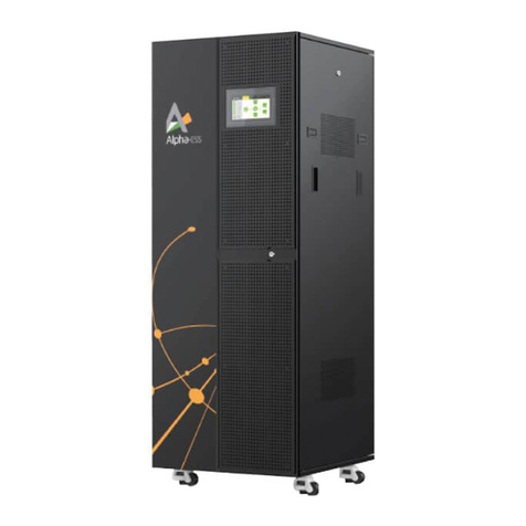
Sinexcel PWS1-500KTL User manual

Installation Manual
PWS1-500K Series Energy Storage PCS

1
Sinexcel
PWS1-500K Series Bi-directional Energy Storage PCS
Installation Manual
Version: V2.0
Shenzhen Sinexcel Electric Co., Ltd.
All rights reserved. In case of any content change, it shall be without prior notice.
Shenzhen Sinexcel Electric Co., Ltd.
Website: http://sinexcel.us/ or www.sinexcel.com
Add: Building 6, Area 2, Baiwangxin High-tech Industrial Park, No. 1002, Songbai Road, Nanshan District,
Shenzhen
Postcode: 518055
Hotline: +86 0755-8651-1588

2
Table of Contents
1 Information on this Document....................................................................................................................3
1.1 Validity...............................................................................................................................................3
1.2 Target Group ......................................................................................................................................3
2 Safety Precautions.....................................................................................................................................4
2.1 Important Safety instructions...............................................................................................................4
2.2 Additional Information.........................................................................................................................5
3 Installation design.....................................................................................................................................6
3.1 Installation process .............................................................................................................................6
4 Storing, lifting and transporting..................................................................................................................7
4.1 Scope of Delivery................................................................................................................................7
4.2 Safety during Transport .......................................................................................................................7
4.2 Transporting the PCS...........................................................................................................................7
4.2.1 Transport and storage...................................................................................................................7
4.2.2 Transporting.................................................................................................................................8
4.3 Unpacking the PCS..............................................................................................................................8
5 Mechanical Installation ..............................................................................................................................9
5.1 Safety during Installation.....................................................................................................................9
5.2 Installation requirements...................................................................................................................10
5.2.1 Environment requirements .......................................................................................................... 10
5.2.2 Ground requirements ..................................................................................................................10
5.2.3 Ventilation.................................................................................................................................. 10
5.2.4 Operation space .........................................................................................................................10
5.2.5 Other requirements .................................................................................................................... 12
5.3 Mounting preparation........................................................................................................................ 12
5.4 Rack installation................................................................................................................................ 13
5.5 Installation in container.....................................................................................................................15
5.5.1 Container internal layout distance................................................................................................ 15
5.5.2 Fan installed inside the container................................................................................................. 16
5.5.3 Fan installed outside the container............................................................................................... 17
5.5.4 Air duct design ........................................................................................................................... 18
5.5.5 Installation of Fan module........................................................................................................... 19
6 Electrical Installation ............................................................................................................................... 20
6.1 Electrical Connections ....................................................................................................................... 20
6.1.1 Input requirement ...................................................................................................................... 20
6.1.2 Output requirement .................................................................................................................... 20
6.1.3 Wiring mode .............................................................................................................................. 20
6.1.4 System grounding....................................................................................................................... 28
6.1.5 DC port wiring ............................................................................................................................ 28
6.1.6 AC port wiring ............................................................................................................................ 29
6.1.7 Wiring of terminal strips.............................................................................................................. 30
6.2 Communication interface................................................................................................................... 33
6.2.1 Connecting the EMS over RS485 or Ethernet ................................................................................ 33
6.2.2 Connecting a BMS over CAN........................................................................................................ 34
6.3 Check after installation...................................................................................................................... 34
7 Installation checklist ................................................................................................................................ 36
8 Start-up and Operation............................................................................................................................ 37
9 Contact...................................................................................................................................................38

3
1 Information on this Document
1.1 Validity
This document is valid for the following device models with or without STS module:
• PWS1-500K
• PWS1-500KTL
• PWS1-500KTL-NA
• PWS1-500KTL-EX
Model definition
This section introduces product model definition in this user's manual, as shown in Fig. 1-1:
PWS1- 500KTL-EX
Rated Power:500K
500KTL: 500K Transformerless
500K: 500K with transformer
Bi-directional Energy Storage PCS
NA: For North America
EX: For Europ and other country
Fig.1-1 Product model definition
For example:
PWS1-500KTL: 500kW Bi-directional storage inverter without isolation transformer.
PWS1-500K: 500kW Bi-directional storage inverter with isolation transformer.
Check the type label for the production version of PCS.
The illustrations in this document have been reduced to be necessary and may differ from the real product.
1.2 Target Group
The tasks described in this document can only be performed by professionals or other qualified persons.
Qualified persons must have the following skills:
• Understand how the product works and how to operate the product
• Understand how the battery works and how to operate the battery
• Training on how to deal with the hazards and risks associated with installing and using electrical
equipment installation
• Installation and commissioning of electrical equipment and installations
• Understand all applicable standards and directives
• Understand and follow this manual and all safety information

4
2 Safety Precautions
2.1 Important Safety instructions
This user’s manual is about installation and operation of Sinexcel PWS1-500K series Bi-directional Storage
Inverter (PCS).
Before installation, please read this user’s manual carefully.
The PCS must be commissioned and maintained by the engineers designated by the manufacturer or the
authorized service partner. Otherwise, it might endanger personal safety and result in device fault. Any
damage against the device caused thereby shall not be within the warranty scope.
The PCS cannot be used for any circumstance or application related to life support device.
This manual contains important instruction for Models of PWS1 series that shall be followed during
installation and maintenance of the PCS.
Any contact with copper bar, contactor and terminal inside the device or connected with the loop of utility
grid might result in burning or fatal electric shock.
Don’t touch any terminal and conductor connected with the loop of utility grid.
Pay attention to any instruction and safety documents about power on-grid.
There might be an electric shock risk inside the device!
Any operation related to this device will be conducted by professionals.
Pay attention to the safety precautions listed in safety instruction and installation documents.
Pay attention to the safety precautions listed in operating and installation manual and other documents.
Large leakage current
Before connecting input power supply, please ensure that the grounding is reliable.
The device must be grounded complying with the local electric codes.
When storage battery is connected to PCS, there may be DC voltage at input port. Please pay attention to it
during operation or check the battery system user manual

5
Don’t touch electric parts within 15 minutes after power outage!
There is dangerous energy in capacitance storage. Don’t touch device terminal, contactor and cooper bar
and other electric parts within 15 minutes after disconnecting all device power supplies.
All maintenance and preservation inside the device require using tools and shall be conducted by trained
person. The components behind the protective cover plate and dam board which are opened by tools cannot
be maintained by users.
Please read this user’s manual before operation.
2.2 Additional Information
Links to additional information can be found at http://sinexcel.us/ or www.sinexcel.com.

6
3 Installation design
3.1 Installation process
Start
Preparations
Lifting and transporting
End
Mechanical Installation
Electrical Installation
Installation Check
Commissioning
startup and operate
Fig. 3-1 Installation Process
Installation process description
Process
Explanation
Chapter
Preparation
Lifting and transporting
4 Storing, lifting and transporting
Mechanical Installation
5 Mechanical Installation
Electrical Installation
6 Electrical Installation
Installation Check
7 Installation checklist
Commissioning startup and operate
8 Start-up and Operation

7
4 Storing, lifting and transporting
4.1 Scope of Delivery
Refer table below for packing list of rack of storage inverter:
Table 4-1 Scope of Delivery
Item
Quantity
Remark
User’s manual
1 copy
Electronic Document
Overall dimension and foundation installation diagram
1 copy
Electronic Document
Schematic diagram
External terminal diagram
Certificate of quality
1 copy
The electronic document can be downloaded from Sinexcel’s website or provided by Sinexcel’s staff.
4.2 Safety during Transport
If the lifted or suspended load falls over, falls or sways, there is a risk of crushing
Vibration or careless or hasty lifting and transport can cause the product to tip over or fall. This can result in
death or serious injury.
All national transport standards and regulations must be respected.
Always transport the product as close as possible to the floor.
Avoid fast or uneven movement during transport.
Always maintain a sufficient safety distance from the product during transportation.
Damaged frame structure of the PCS due to uneven support surface
Placing the PCS on an uneven surface can cause bending, which causes the PCS door to no longer close
properly.
This can cause moisture and dust to seep into the PCS.
Do not place the PCS on an unstable, uneven surface, even for short periods of time.
The unevenness of the support surface must be less than 0.25%.
Do not use the installed kick plate to transport the PCS.
4.2 Transporting the PCS
4.2.1 Transport and storage
The module of the PCS are installed in the PCS cabinet rack during shipping. During device transport and
storage, pay attention to the caution sign on the packing case.
The selection of storing position should ensure that:
• There is no corrosive gas around it.

8
• There are over-wetting and high-temperature sources.
• It is not a dusty environment.
• It complies with the local firefighting requirements.
During rack transport and storage, stacking is not allowed. The device top cannot be placed with other
articles.
The rack should be placed vertically at forward direction. Keep it upright and don’t place it horizontally.
4.2.2 Transporting
When removing the PCS unpacked from packing case, a forklift can be used to remove the whole PCS
cabinet rack.
Users can lift the device bottom with a forklift . There is no lifting hole on its top.
Fig. 4-1 Moving PCS
Before the rack is moved, please ensure that the module is fixed stably.
4.3 Unpacking the PCS
Please take care to protect the PCS inside the package when unpacking.
PCS can’t be inverted and the vertical tilt angle should not exceed 30 degree.

9
5 Mechanical Installation
5.1 Safety during Installation
Risk of electric shock caused by live voltage
There is a high voltage in the live components of the product. Touching field components can result in death
or seriousness electric shock damage.
Wear appropriate personal protective equipment for all work on the product.
Do not touch any live components.
Observe all warning messages in products and documents.
Obey all safety information from the battery manufacturer.
Electric shock hazard caused by DC cable
The DC cable connected to the battery is live. Contact with live cables can cause electrocuted death or
serious injury shock.
Before connecting the DC cable, make sure that the DC cable has no voltage.
Wear appropriate personal protective equipment for all work on the product.
Danger to life due to electric shock when entering the storage system
Damage to the insulation in the storage system can result in fatal ground currents. May cause a fatal electric
shock. Ensure that the insulation resistance of the storage system exceeds the minimum.
Minimum value:The insulation resistance is: 14kΩ.
The PCS must be installed in a closed electrical operating area.
Fire due to failure to observe torque specifications at real-time bolt connections
Failure to comply with the specified torque reduces the current carrying capacity of the live bolt connection,
thereby reducing the contact resistance increase.
This can cause the components to overheat and catch fire.
Be sure to always tighten the live bolt connection using the exact torque specified in this document.
Use only the right tools when working on the device.
Avoid repeatedly tightening the live bolt connection as this may result in unacceptably high torque.

10
5.2 Installation requirements
5.2.1 Environment requirements
It is installed indoor. Direct sunshine, rain and ponding should be avoided.
The installation environment is clean. The air should not contain lots of dust.
The installation position should not be shaky.
Environment temperature should be within the temperature range listed in technical specification.
The installation position is convenient for observing touch screen.
5.2.2 Ground requirements
The rack of the storage inverter needs to be installed on the flat ground. The weight-bearing of the ground
for installation should be greater than 1,000kg/ m2.
5.2.3 Ventilation
The storage inverter is forced air-cooling. Every module has an independent ventilation route. The module
heat dissipation mode is air inlet in the front and air outlet in the rear. The cold air is inhaled from the mesh
openings of front door of the rack. After heat absorption, the hot air is discharged from the mesh openings
of rear door of the rack.
To ensure the quality of air inlet, please carry out installation according to the operation space requirement
in chapter below, and a proper space should be reserved for air inlet and outlet. A blower is recommend to
be installed in the machine room so as to ensure that the heat emitted from the storage inverter can be
discharged outside the room.
At the rear of the rack, heat dissipation should be guaranteed and ventilation equipment needs to be
installed so as to ensure that the heat emitted from the storage inverter can be discharged outside the
machine room.
5.2.4 Operation space
The installation space of the PCS should have a proper distance from its peripheral walls so as to ensure that
the machine door can be opened and closed conveniently and there will be sufficient space for module
insertion and extraction, normal heat dissipation and user’s operation.

11
Fig. 5-1Front and back installation space of storage inverter(Please seen Chapter 5.5 Installation in
container for the recommend fan location)
Position
Description
A front
≥800mm, ensure that the front door of the rack can be fully opened. There is
sufficient space for cold air to enter. Users can conveniently insert and extract the
module and operate the breaker.
B rear
≥800mm, ensure that the rear door of the rack can be fully opened. Please seen
Chapter 5.5 for the air volume requirements and air duct design. Ventilation and
heat dissipation should be ensured. Users can have sufficient space for
maintenance.
Or
B rear ≥200mm when there are cooling fan near the rear door.
The distance between PCS side steel plate and container wall is no less than 50mm to ensure that the PCS
can be installed inside the container.
Fig. 5-2 Side installation space of storage inverter

12
5.2.5 Other requirements
1) Waterproofing
The ingress protection grade of the rack of the Bi-directional Storage Inverter is IP20/NEMA1. It is only
installed and used in a dry and clean room. Water leakage in room should be avoided so as to prevent the
storage inverter from being damaged.
2) Rat-proofing
After wiring, fireproofing mud should be used to seal inlet and outlet holes so as to meet the rat-proofing
requirement. Fireproofing mud is not provided by Sinexcel.
5.3 Mounting preparation
Drilling mounting holes is required in the foundation. The overall dimension of the PCS is shown in figure
below.
Fig. 5-3 Overall dimensions of PCS
The PWS1-500KTL cabinet, width: 1100mm, height: 2,160mm (without lifting rings); depth: 800mm.
The height of the lintel is 60mm and it can be taken down if there is no sufficient height into the room.
The PWS1-500KTL series Bi-directional Storage Inverter is without lifting rings and can’t be lifted.

13
Fig. 5-4 PWS1-500K rack wiring hole in bottom view
There are two hole in each corner, only one hole need to mount bolts, the other hole is used as a spare.
5.4 Rack installation
After the rack is removed to the installation position of BESS (battery energy storage system) with a forklift
or a tool. Fine adjust the rack and remove it to the designed position, open the internal door of rack, use
M10 or M12 screw to fix the rack.
When the rack needs to be fixed on the steel channel, Φ14 holes can be made in the steel channel. Fix the
rack to the steel channel with screws.
Fig. 5-5 Fix the rack to the channel steel
Fig. 5-6 Fix the rack to the concrete floor
When the rack is fixed to the concrete floor, make holes on the floor and fix the rack to the concrete floor
with expansion screws.

14
Module
fastening
bolts
Fig. 5-7 Module fastening bolt position in the back side of each module
After confirming the above items and finished and tested, open the back door of the PCS and remove the
module fastening bolts.
Note: Make sure that the module fastening bolts on the back side of power module have been removed
before moving the converter into the container.
Can contact the manufacture to confirm.

15
5.5 Installation in container
5.5.1 Container internal layout distance
Internal layout can be customized design according to customer’s requirements. Please contact the
manufacture to know the internal layout for specific project.
The distance between PCS side steel plate and container wall is no less than 50mm to ensure that the PCS
can be installed inside the container.
Fig. 5-8 The distance between PCS and container wall

16
5.5.2 Fan installed inside the container
When the fan is installed inside the container, its on the inner side of container door near the ventilation
thermal outlet of the PCS.
The Dimension of the Fan and installation position below is just an examples. Please contact manufacture to
confirm the Fan position for certain project.
Outside
Inside
Fig. 5-9 The Fan on the inner side of container wall

17
5.5.3 Fan installed outside the container
The standard external fan module is recommended and easy to install.
When the fan is installed outside the container, its on the outward side of container door near the ventilation
thermal outlet of the PCS.
Fig. 5-10 Container external fan drawing
Fig. 5-11 Components of Container external fan

18
Fig. 5-12 Three external fan on the outward side of the door
Fig. 5-13 PWS1-500K series Fan and its corresponding Module; Relative position of Fan and back door
5.5.4 Air duct design
Air duct can be customized design according to customer’s requirements. Please contact the manufacture to

19
know the air duct design for specific project.
Model
System air
demand
Ventilation air volume
Fan
Module
Inlet air area
Outlet air
area
PWS1-500K series
5000 M³H
6400 M³H
4
2
0.6 m2
0.8 m2
This ventilation volume requirement is also applicable to the indoor installation.
5.5.5 Installation of Fan module
Fan module (including fans and fan covers) need to be disassembled when the container commissioning and
transportation. The steps for disassembling and waterproofing the corresponding fan and hood are as
follows:
Step 1. Fasten the fan assembly with the screw to the container.
Step 2. Lock the hood fixture with screws, do not tighten, so that it can be adjusted later.
Step 3. After connecting the cable, hang up the fan cover, adjust the fan cover fixing bracket of the step 2 to
the appropriate position and fasten it.
Then fasten the fan cover with the anti-theft screw with flat elastic pad,
Then fix the Four-sided t joint the fan cover and the container body with waterproof glue.
Then the installation is finished.
The removal steps can be reversed from step 3 to step 1.
This manual suits for next models
3
Table of contents
Other Sinexcel Storage manuals
