manuals.online logo
Brands
  1. Home
  2. •
  3. Brands
  4. •
  5. Singer
  6. •
  7. Sewing Machine
  8. •
  9. Singer 231-7 User manual

Singer 231-7 User manual

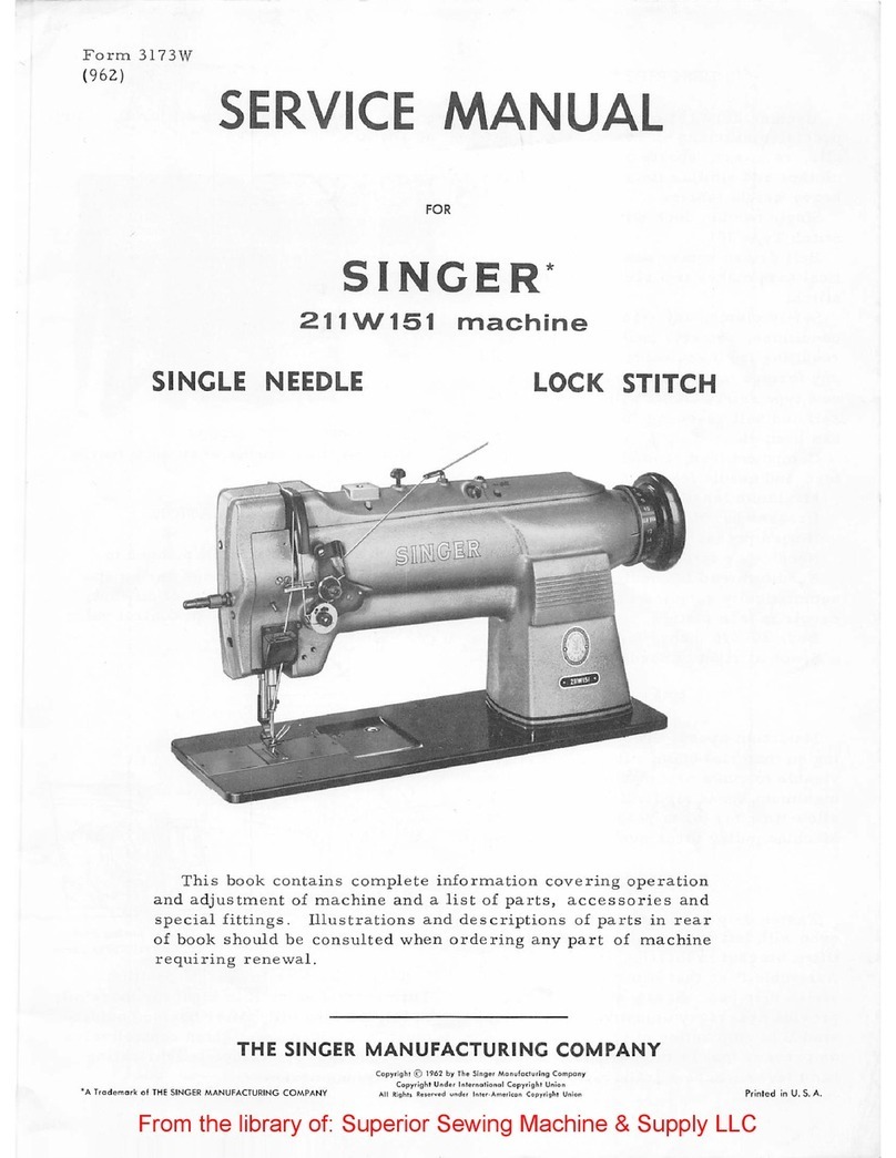
SINGER
231 AND 231-8
From the library of Superior Sewing Machine & Supply LLC - www.supsew.com
7
us~
SINGER.
OILS
and
LUBRICANTS
They
insure
freedom
from
lubricating trouble and
give
longer life
to
sewing equipment
Tlie following
is
the
correcl lubricant
for
the
134w,
152
and
23/
Machines:
TYPE
D -
MANUFACTURING
MACHINE
OIL,
HEAVY
GRADE
OTI-H~R
SINGER
LUBRICANTS
TYPE
E
-THREAD
LUBRICANT
..
Fer
lubricating
the
needle
thread
of
sewing machines
for
stitching fabrics
or
leather
where
a
thread
lubricant
is
required.
TYPE
F -
MOTOR OIL
For
oil
lubricated
motors
and
plain
bearings
in
power
tables
and
transmitters.
NOTE:
All
of
the
above
oils
are
available
in 1
quart,
1
gallon
and
5
gallon
cans.
GEAR LUBRICANT
This
specially
prepared
grease
is
recommended
for
gear
lubrication
on
manufacturing sewing machines.
BALL BEARING LUBRICANT
This
pure
grease
is
specially designed
for
the
lubricotion
of
ball
bearings and boll thrust bearings
of
motors
and
electric
transmitters,
ball
bearing
hangers
of
power
tables,
etc. Furnished in
1
lb.
and
4
lb.
tins.
20858
SERVIC~
MANUAL
FOR
SINGER*
SEWING
MACHINES
231-7
and
231-8
Feed
Off
The
Arm
TWO NEEDLES
AND
TWO LOOPERS
TWO-Tl-IREAD CI-IAIN STITCI-I
Special
attention
is
called
to
the
lubricating
instructions
on
page
5.
Tl-IE SINGER
MANUFACTURING
COMPANY
•;.
Trade
Mark
al
THE
SINGER
MANUFACTURING
COMPANY
Copyright
(<)
1951
by
The
Singer
Manufacturing
Compcmy
From the library of Superior Sewing Machine & Supply LLC - www.supsew.com
DESCRIPTION
FF.ED-OFF-TIJE-ARM
MACHINE
231-7
has
two
needles
and wo
loop-
er:,,
and mak0s
the
two-thrnad
chain
st1
tch
for
lap
seam
felling
work
shirts,
overalls,
trousers,
etc.,
of
medium weigl1t
materials.
MACHINE
2.31-8
is
similar
to
Machine
231-7
but
has
a
longer
n0eclle
bar
stroke
and
is
designed
for
work
in
medium
and
medium
l1c2.vy
weight
me.terials,
Tti<,sre
machines have an
upper
thread
nipper
and a
slack
thread
controller.
::;
t.andc1.rd
E;auges
are
3/lG,
1/4
and
5/lG
inch,
but
the
machines
c::in
t,p
furnished
in
any gauge bet\./een
3/16
and
3/0
inch
1n
steps
of
1/32
inch.
A
splash
oiling
system
oils
the
feed
and
looper
mechanism,
and
the
needle
bar
dr1v1ng
mechanism
is
o1J.ed
through
a
hollow
shaft
rrom
an
oil
reservoir
at
the
machine
pulley
end.
..
SPEED
The
maximum
speed
for
Machine
231-7
ls
3800 R.P.M.
The
maxlnrum
speed
for
Machine
231-8
ls
3600 R.P.M.
The
machines
should
be
driven
at
a
speed
about
200
R.F.M.
lower
than
the
maximum
speeds
for
the
first
three
or
four
days,
after
which
they
can
be
driven
at
the
maximum
speaus
when
per-
mittrd
by
the
nature
of
the
work and
the
ability
of
the
operator.
When
the
machines
are
tn
operation,
the
top
of
the
machine
pulley
turns
toward
the
operator.
CAUTION
After
setting
up,
do
not
start
the
machine,
not
even
to
test
the
speed,
until
it
has
been
thoroughly
oiled,
as
instructed
on
pages
5 and
6,
3
SeHing
Up
Unpack and
thoroughly
clean
the
r;iachine.
Attach
the
counter-
weight
to
the
machine bed
as
shown
1n
Fig.
5.
Insert
the
two
rubber
cushions
(0,
Fig,2)
into
the
holes
in
the
base
of
the
ma-
chine.
Place
the
machine
in
position
with
the
edge
of
the
ma-
chine
base
in
line
with
the
edge
of
the
table
as
shown
below,
and
see
that
the
hole
(N)
for
the
presser
bar
lifter
chain
ls
in
line
with
the
hole
in
the
table
plank.
----=::------
-::._--=-
-
-"=
B
C
'
cr;
Fig.
2 J
Tl~e
two
vibration
dampeners
(J
and
K,F'ig,2)
are
placed
at
the
rear
cf
the
machine
base
and
at
the
right
of
the
counterweie;ht
as
shown 1n
Fig.
2,
Attach
the
straight
straR,s
(L)
to
the
machine
base
and
counterueight,
then
locate
and
drill
holes
in
the
table
and
fasten
tl1e
angle
straps
(K)
of
the
dampeners
to
the
table
with
1/4
X 2
1/4
inch
bolts.
The bed
cover
of
the
macl1ine
should
be
levelled
by
placing
shims
under
the
rubber
cushions
or
the
vibration
dampeners,
Place
a
spirit
level
crosswise
on
the
flat
bed
cover
plate,
and
set
the
machine
with
1ts
arm
rotary
shaft
perfectly
level
so
that
the
oil
will
not
floor\
the
needle
bar
driving
mechanism
in
the
head.
Then
place
the
spirit
level
lengthwise
on
the
flat
bed
cover
plate
and
set
the
bed
of
tlrn
machine
level,
Check
the
setting
occasionally
to
keep
the
machine
level.
When
the
machine
1s
operated
on
11.
SINGERi:
Electric
Transm1
tter
Power
Table
or
a
Low
Shaft
Power
Table,
the
idler
pulley
(M,
Fig.
2)
ls
attached
to
the
machine
counterweight
as
shown
in
Fig.
5.
From the library of Superior Sewing Machine & Supply LLC - www.supsew.com
4
Oiling the Machine
Use
"TYPE
D"
OIL,
sold
by
S1nger
Sewing
Machine
Company,
ror
the
lubrlcatlon
or
these
rnachlnes.
For
description
or
thls
011,
see
lnslde
or
rront
cover
or
this
book.
.,
Fig.
3
All
or
the
011
is
drained
:rrom
thll
arm
reservoir
before
the
machine
ls
shipped
from
the
factory,
therefore
1t
is
absolutely
necessary
that
the
ma.chine be
thoroughly
oiled
according
to
the
following
instructions
before
it
is
started
in
operation:
1,
After
the
machine
has
been
set
up
so
that
its
cylinder
arm
cover
is
level,
lift
out
the
gauge
(A,Flg,3)
and
fill
the
am
reservoir
to
the
level
or
the
mark on
the
gauge.
Ru.~
the
machine
a few
minutes,
then
wipe
off
the
gauge and
recheck
th~
oil
level.
THIS RESERVOrn
SHOULD
BE
FILLED
ABOUT
NICE
A
WEEK
OR
OFTEN
ENOOOH
TO
KEEP
THE
OIL
LEVEL
UP
TO
THE
MARK
ON
THE
GAUGE.
2.
Tum
the
machine
pulley
to
bring
the
screw
plug
(F,
Fig.
4)
to
the
top,
remove
thls
plug
anc!
nu
the
reservoir
practi-
cally
to
the
top.
THE
OIL
LEVEL
IN
TI-!IS
HESERV0IR
SHOl'LD
NEVER
BE
ALLOWED
TO
GO
BELOW
THE
HOLE
AT
THF:
CENTER
OF
IBE
AR1
SHAFT.
5
rr
the
all
level
ls
low,
add
all
berore
starting.
Otherwise
run
the
machine
a few
minutes
before
adding
oll
to
tills
reservoir.
3,
Place
about
5
drops
of
oil
in
each
of
the
three
cups
(B,
C and
D,Fig.3)
Which
lubricate
the
ball
bearings,
and
in
the
cup
(G,Fig.5)
on
the
ldler
pulley
underneath
the
balance
wheel.
DO
THIS
ABOUT
ONCE
A
WEEK.
4.
Place
a
drop
of
oll
once
a
day
1n
the
oil
hole
(Z,Fig,3)
di-
rectly
above
the
nipper.
Fig.
4
NOTICE:
When
the
machine
is
first
set
up,
or
after
it
has
stood
idle
for
some
time,
put
a few
drops
of
oil
in
the
top
of
the
needle
bo.;:-
guide
pin
(E,Fig.3)
before
starting
the
machine.
OIL
DRAIN:
Surplus
oil
from
the
bearings
drains
into
the
wells
at
the
rear
of
the
base
(H,F1G,5)
and
1n
the
head
of
the
arm
(LL,Fig,17),
These
wells
may
be
kept
empty
by
soaking
out
the
oil
with
waste
or
similar
material.
1
Fig.
5
Dll
which
accur,;ulates
tn
the
front
of
the
bed
under
the
rotary
shaft
shculd
be
drained
out
oc-
casi!Jnally
ty
removing
the
screw
plug
at
(P,Fig.3)
in
the
bottom
of
the
bed,
to
prevent
oil
frOi~
getting
on
the
looper
thread
take-up.
Note:
I!
an
excessive
amount
of
011
should
flow
into
the
reserv01r
(LL,Fig,
P),
see
1nstruct1ons
for
replactng
the
w1
eking
ln
the
arm
shaft
crank
on
rage
19.
From the library of Superior Sewing Machine & Supply LLC - www.supsew.com
6
Threading the Needles
Turn
the
machine
pulley
until
the
needle
bar
ts
at
1
ts
highest
pos1t1on.
TO
TI!READ
THE
LEF1'
NEEDLE,
bring
the
thread
from
the
left
spool
(Al,Fig.6)
on
the
unwinder,
down
through
the
hole
(A2)
in
the
thread
gu1do
bar,
then
down
through
each
of
the
eyelets
(A3,
A4
and AS,Fig,7)
in
the
thread
straightener
as
shown.
Pass
the
thread
through
eyelet
(A6), around and
between
the
rear
tension
rt19CS
(A7), through
eyelet
(AB), through the needle
thread
nipper
guide
(9,Fig,8),
between the second and
third
tcnslon
plates
or
nlpper
(10),
through
nipper
guide
(11),
throur,h
the
rear
eyelets
1n
the
slack
thread
regulator
(12)
and
the
takP-llP
thread
g11idos
(13 and
14),
down
uncler
the
retainer
plate
and
through
the
reur
eyelet
in
the
take-up
(15),
dc;,,.m
behind
the
wire
~Jide
(16),
and
from
front
to
back through
the
eye
of
the
le!t
needle
(Al7),
'ID
'IH~
1HE
RirnT
NEEDLE.
bring
the
tllread
dowi
rrom
the
seccnd
,,
sy;;ool
(Bl, F1g.6) on
tbe
unwinder, dovll thIU.lgb !lie
hole
(B2)
1n
the
thread
~ide
bar,
then
down
through
each
or
the
eyelets
(B3
and
B4)
and
up
through
the
eyelet
(BS,
Flg.
7)
ln
the
thread
straight-
ner
as
shown.
Pass
the
thread
throu!ltl
eyelet
~ide
(BB),
throogh
eyelet
(Be),
around
and
between
the
front
tension
discs
(B?),
through
the
eyelet
(BS),
through
the
needle
thread
nipper
~ide
(9, F'ig.
8),
between
the
flrst
and
second
plates
or
the
nipper
(10),
through
the
nipper
gulde
(11),
through
the
fl'ont
eyelets
in
the
slack
thread
regulator
(12)
and
take-up
thread
guides
(13
and
14),
down
under
the
retainer
plate
and
through
the
front
eyelet
in
the
take-up
(15),
down
behind
the
wire
guide
(16),
and
from
front
to
back
through
the
eye
or
the
right
needle
(B17).
Draw
about
two
inches
of
thread
through
the
eyes
of
the
needles
with
which
to
cornnence sewing,
A2
=1.,/,C.
1
15
A3~
'J.¼.)
:.i!f.R .
S2I
~--
Fig.
6
~
~-
13
7
Fig,
7
-~./
~~~¥
~-i;
. 8
B8
mm
<
·"
9
-----~
~
•.,
11
10
..
Fig.
8
From the library of Superior Sewing Machine & Supply LLC - www.supsew.com
8
Threading
the
Loopers
Tum
the
machine
pulley
until
the
needle
bar
ls
at
1ts
lowest
position
to
bring
the
loopers
into
position
for
threading,
swing
open
the
cover
plates
at
the
right
of
the
throat
plate
and on
the
front
and
top
of
the
horizontal
arm.
TO
THREAD
THE
FRONT
LOOPER
or
the
one
nearest
the
operator,
bring
the
thread
from
the
right-hand
spool
(Dl,Fig.6)
on
the
un-
winder,
down
through
the
hole
(D2)
in
the
thread
g11ide
bar,
then
downward
through
each
of
the
eye-
lets
(D3,D4
and
D5,Fig.
q)
1
n
thA
thread
straightener
as
shown.
Pass
the
thread
through
the
ferrule
at
the
end
of
the
thread
tube
(DG)
and
out
thrc•'.ie;h
the
hole
at
(D7),
then
pass
it
from
the
hole
at
(DB)
down
throu~7
the
lower
ferrule
of
the
thread
tube,
as
shown
in
Flg.10.
The
thread
will
automatically
C3
C
l'
✓
L-(j
'
~__::.
C6
C7
slip
through
the
spiral
Fig,
9
slot
int0
the
tube,
In
the
same way,
pass
the
thread
through
the
lower
horizontal
tube
(D9),bet;ween
the
first
and
second
plates
of
the
looper
thread
nipper
(DlO),
through
the
front
eyelet
(Dll),
through
the
hole
1n
the
casting
into
the
wire
guide
(Dl2),
under
Fig.
10
tl1e ta),i::-up
strirper
(D13),
into
the
guide
(Dl1),
into
the
front
slot
(D15) and
under
the
wlre
guard,down
behind
the
thread
retain-
inc;
plutP
(D15),
through
the
thread
tube
(Dl7),
through
the
front
i1ole (D1';)
in
the
looper
thread
guide,
through
thr
holr
(Dl9)
in
9
the
heel
of
the
front
looper,
and
from
front
to
back
through
the
eye
(D20)
of
the
looper.
TO
THREAD
THE
REAR
LOOPER,
bring
the
thread
from
the
spool
(Cl,Fig.6)
on
the
unwinder,
down
through
the
hole
(C2)
1n
the
Cl7
lo
D16
'115
Cl4
--
---1
JTcl'O.'Lrn,i"Ji.
0151
.
13
\
MA/2"K0.V1ul'Jull7"
12
\
1:P~~,,
~
)J•
:<f:
Cl'IJ
~.
D14
.i
,2
l.~-~-.~---=;_
' f
,/-
~
.
--
-~~
D
13
Dl
I
"'"';"'~-
,..
I
thread
guide
bar,
then
downward
0
~'""Cfui.JJL__~~-
~
':~-=
-~~
through
each
of
the
eyel8ts
(C3,
C4
and
c~,F1g,9)
1n
the
thread
straightener,
as
shown,
Pass
the
Fig.
11
thread
through
the
ferrule
at
the
end
of
the
thread
tube
(C6) and
out
through
the
hole
at
(C7),
then
from
the
hole
at
(CS)
through
the
lower
ferrule
of
the
thread
tube,
as
shown
in
Fig.10,
allow-
ing
the
thread
to
slip
through
the
spiral
slot
into
the
Uu·r.ad
tube.
In
the
same way,
pass
the
thread
through
the
upper
hori-
zontal
tube
(C9),
between
the
second
and
third
plates
of
the
looper
thread
nipper
(ClO),
throug)1
the
rear
eyelet
(Cll),
throuch
the
hole
in
thP
cast-
ing
into
the
wire
guides
(Cl2
and
Cl3),
under
the
talrn-up
stripper
(Cl4),
into
the
guide
(Cl5),
into
the
rear
slot
(Cl6)
and
under
the
wire
guard,
down
behind
the
thread
retaining
plate
(Cl7),
through
the
thread
tube
(Cl8),
throu~h
the
rear
hole
(Cl9)
in
the
looper
Fig.
12
thread
guide,
throur;h
the
hole
(C20)
in
the
heel
of
the
rear
loop-
er
and from
front
to
back
through
the
eye
(C21)
of
the
looper.
Dr2.w
about
t;wo
inches
of
thread
through
the
eye
of
each
loop-
er
wl
th
which
to
comnence se,..:1ng.
From the library of Superior Sewing Machine & Supply LLC - www.supsew.com
10
Needles
Needles
for
Machine 231-7
are
of
Class
and
Variety
149x3
for
regular
work and
149x4·for
overalls.
Needles
of
Class
and
Variety
149X3 and
149X4
are
furnished
ln
sizes
16, 17, 18,
19, 20, 21, 22
and
23.
Needles
for
Machine 231-8
are
of
Class
and
Variety
149:x5
for
regular
work and 149x6
for
overalls.
Needle~
or
Class
an(j
Variety
l49x5
3Ild
149xt'l
are
rurnlshed
ln
sizes
18,
19,
m,
21
and
22.
The
si,:e
or
the
needles
to
be
used
should
be
detennlned
by
the
size
of
the
thread,
whlch
must
pass
freelY
throug-)1 tl1e
eyes
or
the
needles.
Ir
rough
or
uneven
thread
is
used,
or
1f
it
passes
wt
th
difficulty
through
the
eyes
of
the
needles,
the
machine
cannot
stltch
perfectly.
.,.
Orders
for
needles
must
specify
the
QUANTITY
required,
the
SIZE
m1ITJber,
and
the
CLASS
and
VARIETI
mrrnbers
separated
by
the
letter
L
The
following
is
an
example
or
an
intelllgible
order:
"100
No.
19, 149x3
Needles"
n1e
best
stitching
results
w111
be obta1ned
when
using
needles
sold
by
Singer
Sew1ng
Machine company.
To
Set
!:he
Needles
TUrn
the
machine
pulley
over
toward
:rou
until
the
needle
bar
moves
up
to
1
ts
highest
position,
and
loosen
the
two
set
screws
in
the
needle
clamp.
Place
the
needles
up
into
the
needle
clamp
as
far
as
they
wlll
go,
wl
th
the
slngle
continuous
groove
in
each
needle
toward
you,
then
t1
ghten
the
two
set
screws.
II
To
Regulate
the
Pressure on
the
Material
The
pressure
of
the
preseer
foot
on
the
material
should
be
heavy
enough
so
that
the
feed
will
move
the
work
evenly.
To
in-
A2
,,'
··.
'
•'
-I
!~'.-
,'
'~
\
✓
u
~t
..
~~<
~-=-
.
Fi
6, 13
crease
the
pressure,
turn
the
wing
nut
(Q)
downward.
To
decrease
the
pressure,
turn
the
wlng
nyi'.
upward.
To Regulate
!:he
Tensions
The
tension
on
the
needle
threads
is
regulated
by
the
thumb
nuts
above
the
tension
discs
at
the
top
of
the
mact1inc.
The
needle
threads
require
sufficient
tension
to
set
the
stitch
pro-
perly
in
the
goods.
The
tension
on
the
looper
threads
is
re
8,"Ula
ted
by
turning
the
screw
at
the
front
of
the
looper
thread
tension
plates
(DlO,
Fig,10)
to
the
right
for
more
tension
or
to
the
left
for
less
ten-
sion,
Tlle
looper
threads
should
have
only
enough
tension
to
con-
trol
the
thread,
From the library of Superior Sewing Machine & Supply LLC - www.supsew.com
12
To Regulate the Length of Stitch
The
length
of
the
stitch
is
controlled
by
the
feed
eccentric,
which
may
be
adjusted
by
removing
the
screw
plug
(U,F'ig.13)
in
Fig.
14
the
front
or
the
bed
cover.
F1rst
turn
the
machlne
l)Ulley
to
bring
the
lock
screw
(V,Fig.14)
underneath
the
hole,
and
loosen
this
locR
screw.
Then
turn
the
large
scrr,w
(W)
which
projects
beyond
the
body
or
the
eccentric,
to
the
le
ft
or
out\,1ard
for
a
longer
stitch,
or
to
the
right
for
a
shorter
st1tcl1.
Tighten
the
lock
screw
(V)
and
replace
the
screw
plug.
NOTE: The instructions on the
following
pages
are
for
Adjusters
and
Mechanics
only.
To
insure
proper
timing
and
avoid
unnecessary
repetition
these
instructions should
be
followed
in the
order
given.
l
13
To Time
and
Set
the Loopers
in
Relation to the Needles
The
loopers
should
be
at
tlie
end
of
their
backward
stroke,
with
the
points
farthest
from
the
need1es,
at
the
same
time
that
the
needle
bar
is
at
1
ts
lowest
point.
In
this
pos
1
t1on,
the
point
of
the
front
looper
should
be
abo11t
9/64
inch
from
the
cen-
ter
of
the
front
needle.
The
loopers
may
be moved
to
this
po-
sition
after
loosening
tho
clamp-
ing
screw
(CC,Fig.15),
The
loop-
er
t1minr
is
set
by
h:iving
the
first
(when
turning
toward
the
operator)
of
the
two
set
screws
in
the
looper
eccentric
(S2,Fig.
21)
bear
against
a
flat
on
the
shaft.
If
tho
belt
has
been
removed
or
disturbed,
the
lower
shaft
must be
timed
by
loosening
the
Fig.
15 l
two
set
screws
and
the
cap
screw
(E2 and
F2,Fig,20)
in
the
lower
belt
pulle:;,
and
turning
the
lower
shaft
until
the
loopers
are
correctly
timed
with
the
needles.
T1p;:1ten
the
cap
screw
(E2)
t'irst,
then
the
two
set
screws,
To Time the Needle-Avoiding Motion of
!:he
Loopers
The
sidewise
or
needle-avoiding
motion
is
produced
by
the
ec-
centric
at
the
right
of
the
feed
eccen~ric,
on
the
lower
slrnft.
The
loopcrs
should
just
clear
the
bacl:
of
the
needles
on
thP1r
forward
strolrn,
and sl1ould
clear
the
front
of
the
needles
on
tllo
backward
stroke.
A change
in
the
t1rnjng
of
.rhe
eccentric
will
make
the
loopers
come
closer
to
or
far~her
tfom
the
needles
and
therefore
a
different
setting
is
requ1 'ed
for
different
sizes
of
needles.
To
adjust
the
eccentric,
remove tl1'"
cy11p,1er
arm
cover
and
tum
machlne
pulley
until
one
or
tl1e two
set
screws
apl)ears
under
the
hole
(V2,Fig.21).
Loosen
this
screw
about
a
quartor-
turn,
leaving
it
.below
the
surface
of
the
eccentric
so
that
1t
will
not
score
the
inside
of
the
bear·ing.
Bring
the
other
SPt
screw
under
the
hole,
loosen
it
and
ledve
the
screwdriver
in
the
slot
to
hold
the
eccentric
wl11le
turning
the
shaft
to
obtain
the
desired
adjustment.
To
bring
the
loopers
the
same
distance
from
the
needles
on
their
forward
and backward
strokes,
th~y
may
be moved
sideways
on
the
looper
shaft
after
loosening
clamring
screw
(CC,Fig.15).
From the library of Superior Sewing Machine & Supply LLC - www.supsew.com
14
To
Set
the Needle Guard
The
function
ot
the
needle
guard
(BB,Flg.15)
ls
to
prevent
the
needles
springing
into
the
path
ot
the
loopers
when
the
loop-
ers
are
on
their
foNard
stroke.
The
needle
guard
should
be
set
as
close
as
possible
to
the
needles
without
touching
them.
To
set
the
needle
v~ard,
loosen
the
set
screw
(FF,Flg.16)
underneath
the
end
of
the
bed and
move
the
needle
guard
to
the
correct
posi
t1on.
Fig,
16
To Set the Feed
Dog
at the Correct
1-ieight
When
the
feed
dog
is
at
its
highest
position,
practically
the
full
depth
of
tl!e
teeth
should
project
through
the
slots
1n
the
throat
plate.
The
feed
dog
may
be
raised
or
lowered
by
turning
the
eccentric
pin
(GG,Fig.16)
a
part
of
a
turn
1n
either
direc-
tion,
It
1s
not
necessary
to
lock
this
eccentric
pin,
as
the
necessary
friction
is
provided
by
pressure
of
a
set
screw
and
leek
nut
inside
the
bed.
Thread Cutter
To
remove
the
thread
cutter
blade
for
honing,
take
out
the
two
screws
(DD,F1g.16),
To Set the Needle
Bar
When
the
points
of
the
loopers
reach
the
centers
of
the
needles
on
the
upward
stroke
or
the
needle
bar,
the
eyes
of
the
needles
should
be
about
1/8
inch
below
the
looper
points,
so
that
the
o·es
or
the
needles
and
the
eyes
of
the
loopers
will
be
in
perfect
alignment
when
they
pass
each
other,
15
The
needle
bar
may be
raised
or
lowered
after
loosening
the
clamping
screw
(l'r.1,Flg.17),
Fig.
17
To
Set
the Needle Thread T
ake-,up
The
needle
thread
take-up
(00,Fig.17)
1s
usually
set
so
that
the
top
of
1ts
clamp
is
about
1/16
inch
below
the
top
of
the
needle
bar.
•
Adjustment of the
Auxiliary
Thread Take-up
The
auxiliary.
thread
take-up
(QQ,Fig,17)
at
the
front
of
the
machine
should
be
set
high
enough
so
that
it
takes
up
the
slack
or
the
needle
threads
after
the
loopers
have
shed
the
needle
loops
and
as
the
needle
bar
finishes
its
downward
stroke
and
the
st1
tch
is
set.
For
some
threads
it
will
be
necessary
to
set
the
auxiliary
thread
take-up
at
a
height
different
from
th~t
required
by
others,
owing
to
the
differences
in
finish,
t-wist,
elasticity,
etc.
From the library of Superior Sewing Machine & Supply LLC - www.supsew.com
16
To Adjust the Slack Thread Regulator
The
slack
thread
regulator
(S,Fig.13)
should
be
sot
so
that
when
the
loopers
are
shedding
tl1e
needle
loops
on
their
backward
stroke,
the
thread
will
not
snap
off
the
points
of
the
loopers
nor.be
drawn
through
the
tension
discs
with
enough
tension
to
break
the
thread,
To
set
the
slack
thread
regulator,
it
is
best
to
start
it
in
a
low
position
and
continue
raising
1t
until
the
loopers
back
out
of
the
needle
loops
with
a
little
tension
on
the
thread.
To
make
this
adjustment,
loosen
the
clamping screw
(B2,Fig,2)
and
raisr;
or
lower
the
slacl:
thread
regulator
as
may
be
required,
then
securely
tighten
the
clamping screw (B2).
I
~
--
. . .
I
I
I
,,
1.....
'~\
·
..
_
...
-
..
I
\'.\~
&11.
\,_
jtt
f
~\
1
---
TT
FW4Z·
Fig.
18
To
Adjust
l:he
Needle
Thread
Tension
Releaser
..
Tl1e
function
of
the
needle
thread
tension
releaser
ls
to
re-
lease
the
tension
on
the
needle
threads
when
the
presser
foot
is
raised.
If
the
tension
releaser
does
not
release
the
threads
when
the
presser
foot
is
raised,
or
1f
the
tension
is
partially
released
when
the
presser
foot
is
down,
loosen
the
set
screw
(UU,
Fig,18)
and
turn
the
shaft
(TT)
to
the
right
or
left
until
the
correct
adjustment
ls
obtained,
then
tighten
the
set
screw.
To
Adjust
the
Needle
Thread
Nipper
The
automatic
thread
nipper
(A2,Fig.13)
at
the
front
of
the
machine
makes
it
possible
to
set
the
stitch
tightly
without
using
a heavy
tension
on
the
needle
threads.
The
nipper
plates
should
open wide enough
to
allow
the
thread
to
pass
freely
between
the
plates,
and
should
close
and
nip
the
17
thn,ad
immediately
after
the
leapers
have
cast
off
the
needle
loops
on
the
downward
stroke
of
the
needle
bar,
To
a<jjust
the
nipper,
loosen
the
S()t screw
(C2,F1g.13)
in
the
arm
above
the
nipper
plates
and
slide
the
nipper
body
inward
or
away
from
you
for
a
greater
opening
of
the
plates,
or
outward
for
a
smaller
opening and
earlier
closlnc
of
the
plates.
\./lien
the
desired
ad-
justment
is
obtained,
tighten
the
set
screw
(C2).
To Time the Looper Thread Take-up
The
straight
part
of
the
talce-up
(VV
,Fig,19)
sl10ulcl
touch
the
thread
between
the
take-up
stripper
wires
(W)
just
as
the
loopers
(J)
0 I
I,
i :I
(])ii
I
(!]
xx
/
£/:'r56
Fig.
19
J
start
their
backward
or
loop-sheddinc;
motion.
The
take-up
acts
also
as
a
thre~d
pull-off
and
should
draw
most
of
the
thread
through
the
tension
discs
on
the
backward
stroke
of
the
loopers,
so
that
the
loopcrs
on
their
forward
stro~e
will
just
draw
the
thread
taut
or
pull
a
small
amount
of
thread,
The
take-up
may
be
advanced
to
draw more
thread
during
the
back
stroke,
or
retarded
to
draw
less
thread,
after
loosening
the
set
screw
in
the
hub
of
the
take-up,
To
Time
lhe Feed
The
set
screw (T2,F1g,21) 1n
the
feed
eccentric
should
boar
against
the
flat
on
the
shaft.
The
feed
lifting
eccentric
is
connected
to
the
looper
eccen-
tric
and
ls
timed
as
Instructed
on
oage
13.
From the library of Superior Sewing Machine & Supply LLC - www.supsew.com
18
To Remove
and
Replace the
Arm
Shaft Connection
Belt
Remove
the
needles
to
orevent
damage
v.tille
the
needles
and
loooem
are
out
or
tlme. Unscrew
the
machine
pulley
all
reservolr
rrom
the
shart.
Loosen
the
two
set
screws
ln
the
machine
pulley
belt
groove.
and
remove
the
machine
pulley.
Take
out
the
two
screws
which
h0ld
the
belt
guard
cover
and remove
the
cover.
The
belt
may
be
easily
slipped
orr
the
lower
belt
pulley,
then
the
upper
pulley.
Fig.
20
When
replacing
the
belt,
first
place
it
over
the
upper
pul-
ley,
having
the
needle
bar
at
its
hir,hest
position.
Turn
the
lower
oulley
until
the
reed
doc
1,,
up and th,:,
loopers
all
the
way
forward.
Keei:;ing
the
pulleys
in
time
with
each
other,
place
the
belt
on
the
lower
pulley.
If
the
upper
pulley
is
removed
or
disturbed,
it
should
be
re-
set
as
follows
when
r1:plac1nr:
the
belt.
Turn
one
of
the
set
screws
(H2,Fie;,20)
lightly
into
the
groove
in
tl1e
am
shaft,
then
place
the
belt
on
the
pulleys
and
hang
the
belt
guard
cover
over
the
shart.
Place
the
machine
pulley
on
the
shaft
and
tum
one
or
the
set
screws
in
the
belt
groove
lightly
into
the
groove
in
the
shaft,
Insert
and
tighten
the
arm
shaft
oil
reservoir
to
draw
the
pulley
ae;a1nst
the
ball
bearing.
Tighten
the
two
set
screws
(H2)
in
the
upper
pulley
and
also
those
in
the
belt
groove
of
the
balance
wheel.
The
belt
guard
cover
may
be swung
out
of
the
way
wl thou t
removing
the
machine
p111ley,
1n
order
to
reach
the
lower
pulley
for
timing
the
lower
shaft.
19
To
Remove the Arm Shaft
(
See
Fig.17)
Remove
face
plate,
presser
foot
and
needles.
Remove
the
bal-
ance
wheel,
belt
guard
cover
and
belt,
as
instructed
on
page
17.
Remove
the
upper
belt
pulley.
Loosen
tl1e
presser
bar
lifter
bracket
clamp
screw
(KK,Fig,17)
and
withdraw
the
presser
bar
from
the
top.
Loosen clamp
screws
(M'·1
and
NN),
remove
the
thread
take-
up and
allow
the
needle
bar
to
drop
downward,
Loosen
set
screw
(SS) and
tap
the
needle
bar
guide
pin
(RR)
out
through
the
top,
Then
tap
the
shaft
o~t
through
the
needle
bar
cnd,w1th
the
crank,
oil
retainer
ring
and
ball
bearing.
TO
RLMOVE
ONLY
THF:
APJ-1
~,HAFT
CPJJrn:,
lower
the
needle
bar
and
remove
the
presser
bar
ar;
lnstrw::ted
above,
take
out
the
large
cap
screw
(PP,F1G,J7)
in
the
crank,
and
loosen
the
two
large
set
screw::;
in
1
ts
perimeter
which
arc
accessible
through
the
hole
in
tlie
rear
of
the
castit1£.
The
smaller
scrnw
;1hich
1s
also
visible
through
the
hole
in
the
c:asting
should
not
be
molested.
The
crank
may
then
be removed from
the
shaft.
When
replacing
the
arm
shaft
cranl-:, 1t
ls
important
to
have
the
pin
(JJ)
opposite
the
oil
hole
in
the
shaft,
in
which
posi-
tion
the
two
set
scre;:s
will
be
opposite
flats
on
the
shaft.
Turn
the
set
screws
loosely
against
the
flats,
tighten
the
large
cap
screw
(PP),
then
t1g,1ten
the
set
screws,
To Replace the
Wicking
in
the Needle
Bar
Link
Hinge Stud
'Ilrn
rupply
or
oll
ln
the
reservoir
at
the
~111ter
of
t.1e
machine
pulley
should
ordtnarlly
last
ror
about
1two
days
before
it
goes
below
the
center
of
thr
hole
in
the
shaft.
If
too
much
oil
1.s
lost
into
the
well
around
the
neeC.:
le
bar,
a
longer
piece
of
wicking
should
be
packed
in
the
needle
bar
11nk
pin
1n
the
arm
shaft
crank,
Remove
the
presser
bar
and
drop
the
needle
bar
as
instructed
above,
then
remove
the
needle
bar
linl,.
Toe
wick
may
be
:-eplaced
without
removing
the
arm
shaft
crank.
To Remove
!:he
Lower
Rol:ary
Shaft
Remove
the
arm shG.ft
connection
belt,
the
belt
pulleys
and
the
belt
c:ard
(G2,Fig.20).
nernove
Urn
horizontal
thread
tube
plate
at
the
front
of
the
bed,
and
loosen
the
set
screw
under-
neath
it
which
holds
the
right
ball
bearing
case.
Remove
the
tG.ke-up
stripper
plate
(XX,Fic.10)
2nd
loosen
the
set
screw
in
the
take-up
(W
,Fig.19).
Loosen
the
two
set
screws
in
the
inter-
From the library of Superior Sewing Machine & Supply LLC - www.supsew.com
..
20
mediate
ball
bearing
hub,
which
is
Just
to
the
left
of
the
take-
up,
Loosen one
of
the
set
screws
in
the
looµcr
avoiding-motion
eccentric
(V2,Fig.21),
but
do
not
back
the
screw
out
far
enough
to
scorn
the
bearing
when
the
shaft
is
turnrd
to
bring
the
other
set
screw
under
the
hole.
Back
out
the
second
screw
into
the
hole
1n
the
sleeve
to
hold
the
eccentric
in
po:::,i
tion
when
the
shaft
is
removed, Loosen
the
two
set
screws
(T2
and
U2)
in
the
feed
eccentric,
also
the
two
oet
ocrews
in
the
feed
lifting
and
looper
motion
eccentric
(S2).
Remove
the
plate
(T,Fig.13)
and
t'lke
out
the
cap
screw
at
the
left
end
of
the
shaft.
Withdraw
the
shaft,
with
the
right
bearing
case,
from
the
pulley
end.
J
K
L2
M2
02
P2l
Q2
I
21
• T2.1
.
/_•-----'=="'·
S2~=c=aa=c===~E~,•~s,d~a
To
Remove
lhe
i=eed
Bar
Remove
the
presser
foot,
throat
plate
and
feed
dc6, Lr:
1
J::;en
nut
(K2,
Fig.21)
and
back
out
the
friction
screw
(J2)
until
th8
eccentric
p1n
(
22)
c
2.n
be
push
0
d
OU
t,
Swing
the
feed
bar
upright
and
take
out
the
t\-10
screws
(W2).
S11(1c
the
feed
11ftine;
fork
(Q2)
upward
and
Or.ff,
then
lower
the
fyed
b~r
to
a
hori-
zontal
position
2.nd
11ft.
1t
off
the
eccentric
block.
To
Remove
the
Looper
N1echanism
Loooen
screws
(F:E
and
IT,Fig,16),
remove
the
nPedle
guard
and
the
needle
f'.1,lard
holder
(AA,Fig.15),
Loosen
the
clamp!ng
sc:rew
(CC
,Fig.15)
and
remove
the
looper
holder
from
the
looper
shaft.
Loosen
the
clamp-
ing
screws
(12 and
Y2,Fig.21)
in
the
looper
driving
a:nn
and
the
adjust-
able
collar.
The
looper
shaft
may
be
with
drawn
through
tl1e
needle
guard
holder
opening
at
the
looper
end
of
the
bed,
Fig,
21
To
remove
the
looper
driving
mechanism
c1mplete,
first
remove
the
lower
rotary
shaft.
Loosen
the
set
screw
(02,Fig.21)
and
dr1ve
out
the
top
pin
(P2).
Loosen
the
two
set
screws
in
the
collar
directly
under
the
pin
(P2),
and
the
set
screw
(M2),
then
unscrew
the
lower
pin
(HH,Fig.16),
The
entire
assembly
may
new
be
lifted
out.
Remove
the
two
screws
(X2)
and
11ft
out
the
bloclc
with
the
looper
avoiding-motion
shaft
and
fork.
TO
ALL
WHOM
IT MAY CONCERN:
The
improper placing or renewal
of
the
Trade
lv\11rk
"SINGER"
or
any
other
of
the
Trade
Marks
of
The
Singer Manufacturing Company
(all
of
which
are
duly
Registered
Trade
Marks)
on
any
machine
that
has
been
repaired,
rebuilt,
reconditioned,
or
altered
in any way
whatsoever
outside
a
SINGER
factory
or
an
authorized
SINGE:R
agency
is
Forbidden.
THE
IMPORTANCE OF USING
SINGER*
PARTS
AND
NEEDLES
IN
SINGER
MACHINES
The
successful
operation
of
SINGER
machines
can only
be
assured
if
SINGER
parts
and
needles
are
used.
Supplies
are
available
at
all
SINGER
Shops
For
the
Manufacturing
Trade,
and mail
orders
will
receive
prompt
attention.
SINGER
Needles
should
be
u/ed
in
SINGER
Machines
These
Needles
and
their
Containers
are
marked with
the
Company's
Trade
Mark
"SIMANCO.*"
Needles
in
Containers
marked
"FOR
SINGER
MACHINES"
are
NOT
SINGER
made
needles.
2

Other manuals for 231-7

1

This manual suits for next models

1

Other Singer Sewing Machine manuals

Singer 1191D200A User manual

Singer

Singer 1191D200A User manual

Singer 22W204 User manual

Singer

Singer 22W204 User manual

Singer 112-4 User manual

Singer

Singer 112-4 User manual

Singer 300wl03 User manual

Singer

Singer 300wl03 User manual

Singer 147-114 User manual

Singer

Singer 147-114 User manual

Singer Quantum User manual

Singer

Singer Quantum User manual

Singer 98-3 User manual

Singer

Singer 98-3 User manual

Singer 312 U141 User manual

Singer

Singer 312 U141 User manual

Singer 153W102 Quick start guide

Singer

Singer 153W102 Quick start guide

Singer 15K80 Setup guide

Singer

Singer 15K80 Setup guide

Singer 4411 User manual

Singer

Singer 4411 User manual

Singer Fashion Mate 239 User manual

Singer

Singer Fashion Mate 239 User manual

Singer 400W11 Quick start guide

Singer

Singer 400W11 Quick start guide

Singer 30215 User manual

Singer

Singer 30215 User manual

Singer CG-590 User manual

Singer

Singer CG-590 User manual

Singer QUANTUM QUILTER 7350 Operation instructions

Singer

Singer QUANTUM QUILTER 7350 Operation instructions

Singer 16-133 Quick start guide

Singer

Singer 16-133 Quick start guide

Singer 178-1 User manual

Singer

Singer 178-1 User manual

Singer QUANTUM L-500 User manual

Singer

Singer QUANTUM L-500 User manual

Singer QUANTUM 9940 Operation instructions

Singer

Singer QUANTUM 9940 Operation instructions

Singer 247-1 Quick start guide

Singer

Singer 247-1 Quick start guide

Singer 150W161 Quick start guide

Singer

Singer 150W161 Quick start guide

Singer Inspiration 4220 User manual

Singer

Singer Inspiration 4220 User manual

Singer 678B002 Troubleshooting guide

Singer

Singer 678B002 Troubleshooting guide

Popular Sewing Machine manuals by other brands

Brother SC6600 Manual de instrucciones

Brother

Brother SC6600 Manual de instrucciones

Brother Dream Quilter 15 instruction manual

Brother

Brother Dream Quilter 15 instruction manual

Bernina Bernette 20 quick start guide

Bernina

Bernina Bernette 20 quick start guide

Brother DreamWeaver XE VM6200D manual

Brother

Brother DreamWeaver XE VM6200D manual

Pfaff 1196 Instruction book

Pfaff

Pfaff 1196 Instruction book

Semco Indigo 6 instruction manual

Semco

Semco Indigo 6 instruction manual

Siruba ASP-EBJ100 Instruction book

Siruba

Siruba ASP-EBJ100 Instruction book

Brother T-8752B parts manual

Brother

Brother T-8752B parts manual

JUKI MF-7900-E22 instruction manual

JUKI

JUKI MF-7900-E22 instruction manual

Duerkopp Adler 550-767 installation instructions

Duerkopp Adler

Duerkopp Adler 550-767 installation instructions

Pfaff Sewing Machine Instruction book

Pfaff

Pfaff Sewing Machine Instruction book

Janome 109 Instruction book

Janome

Janome 109 Instruction book

Dürkopp Adler 567 CLASSIC Service manual

Dürkopp Adler

Dürkopp Adler 567 CLASSIC Service manual

JUKI HZL - 353Z Series instruction manual

JUKI

JUKI HZL - 353Z Series instruction manual

Baby Lock imagine BLE1AT-2 instruction manual

Baby Lock

Baby Lock imagine BLE1AT-2 instruction manual

Gemini STITCH-L100 manual

Gemini

Gemini STITCH-L100 manual

HappyJapan HCH Plus Instruction book

HappyJapan

HappyJapan HCH Plus Instruction book

Pfaff 5625-657/01 instruction manual

Pfaff

Pfaff 5625-657/01 instruction manual

manuals.online logo
manuals.online logoBrands
  • About & Mission
  • Contact us
  • Privacy Policy
  • Terms and Conditions

Copyright 2025 Manuals.Online. All Rights Reserved.