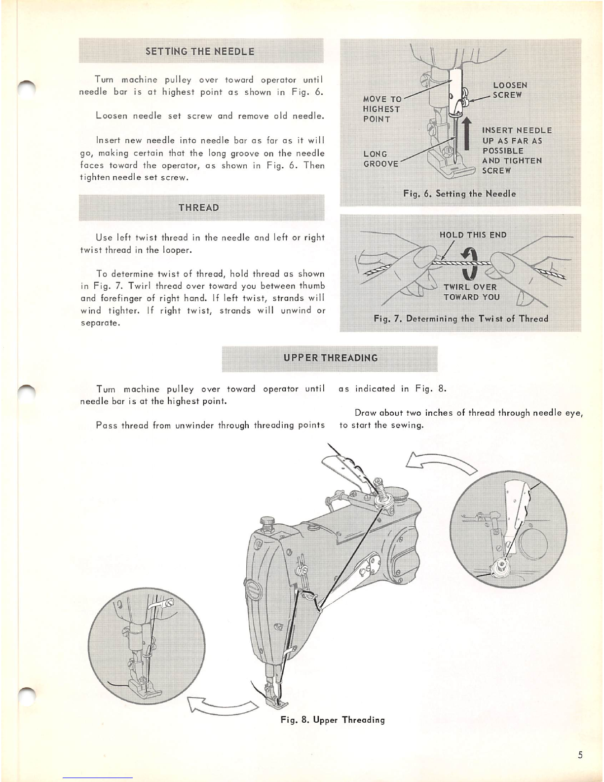
BIGHT
Width
of zig-zag movement of the needle, while
stitching,
is termed the
"BIGHT".
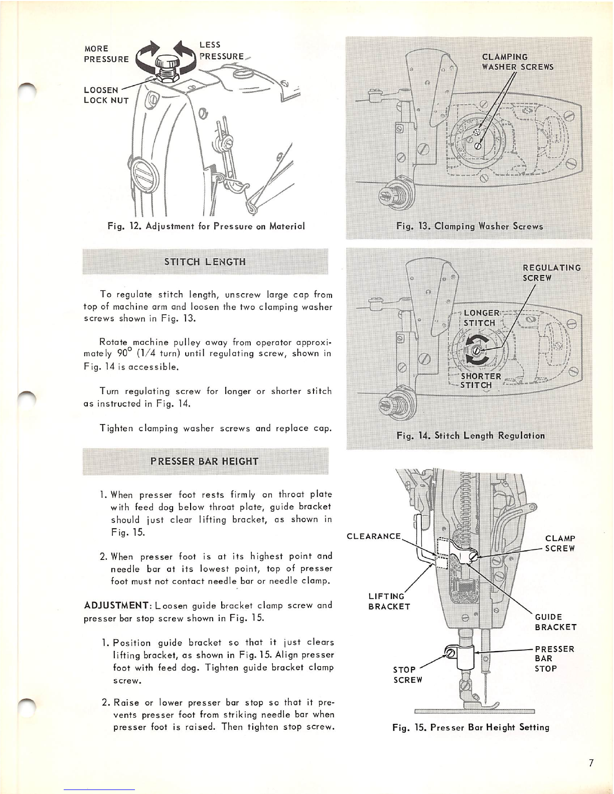
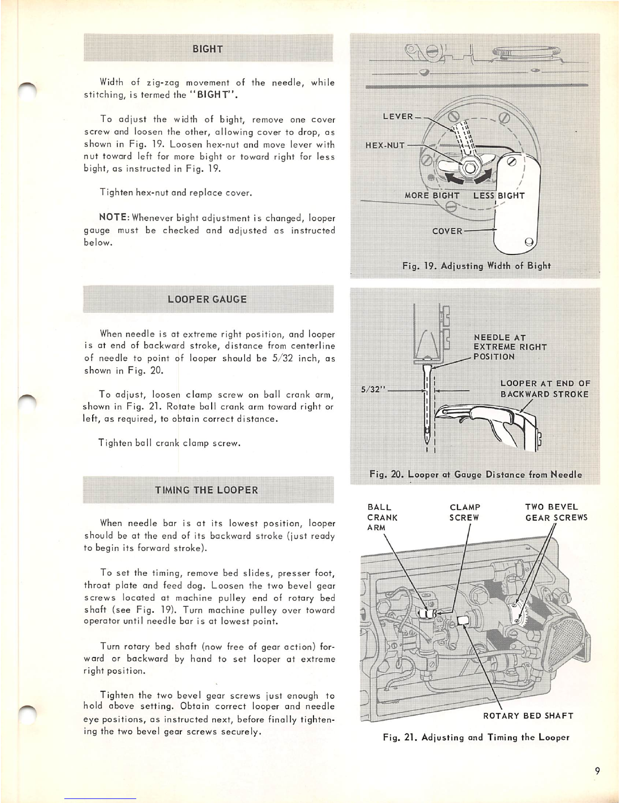
To
adjust
the
width of bight, remove one cover
screw and loosen the other, allowing cover to drop, as
shown in Fig. 19.
Loosen
hex-nut and move lever with
nut
toward left for more bight or toward right for
less
bight,
as
instructed
in Fig. 19.
Tighten hex-nut and
replace
cover.
NOTE: Whenever bight adjustment is changed, looper
gauge must be checked and adjusted
as
instructed
below.
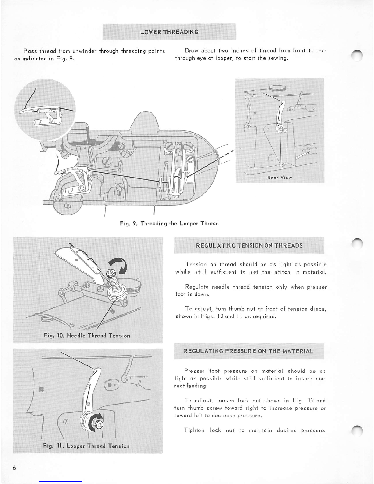
LOOPER
GAUGE
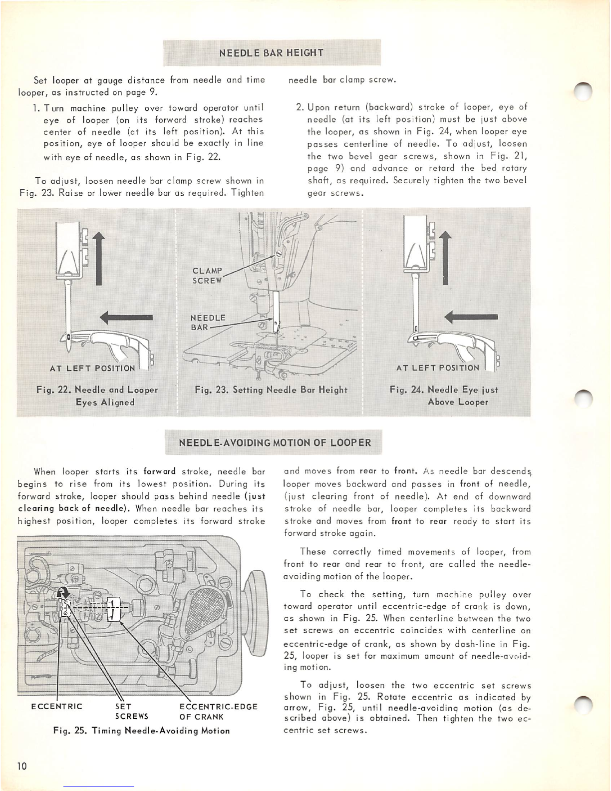
When
needle
is at extreme right position, and looper
is
at end of
backward
stroke,
distance
from
centerline
of
needle
to point of looper should be
5/32
inch,
as
shown in Fig. 20.
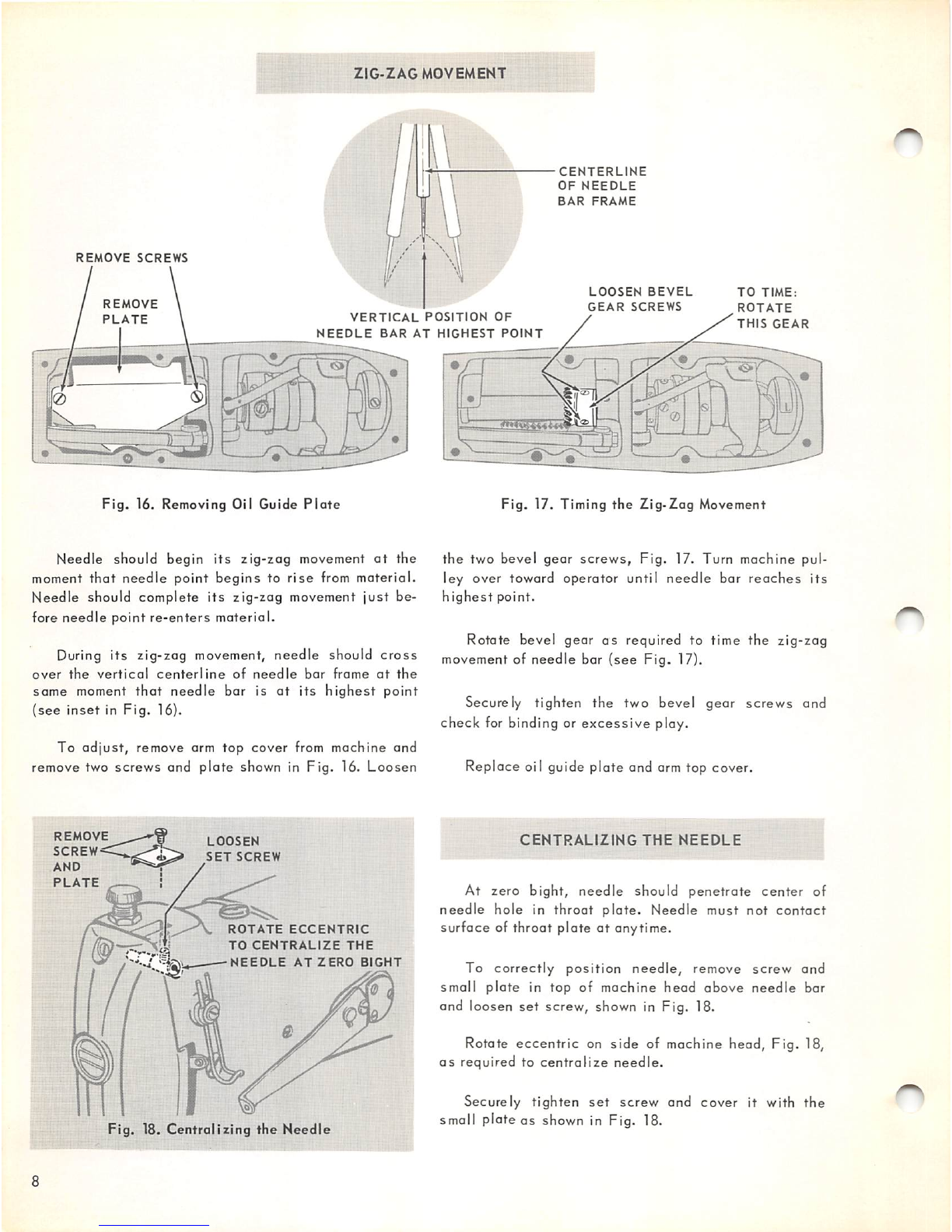
To
adjust,
loosen
clamp
screw
on ball
crank
arm,
shown in
Fig.
21.
Rotate
ball
crank
arm toward
right
or
left,
as
required, to obtain correct
distance.
Tighten ball crank clamp screw.
TIMING
THE
LOOPER
When
needle
bar is
at
its
lowest
position, looper
should be at the end of its backward stroke (just ready
to begin
its
forward
stroke).
To
set
the timing, remove bed
slides,
presser foot,
throat plate and feed dog. Loosen the two bevel gear
screws
located
at
machine pulley end of rotary bed
shaft (see Fig. 19). Turn machine pulley over toward
operator
until
needle
bar is at
lowest
point.
Turn rotary bed shaft (now free of
gear
action)
for
ward or backward by hand to
set
looper
at
extreme
right
position.
Tighten the two bevel
gear
screws
just
enough to
hold above
setting.
Obtain
correct
looper and
needle
eye
positions,
as
instructed
next, before finally
tighten
ing the two bevel gear screws securely.
HEX-NUT
MORE
BIGHT
LESS
BIGHT
Fig. 19. Adjusting Width of Bight
5/32*
NEEDLE
AT
EXTREME
RIGHT
POSITION
LOOPER
AT
END
OF
BACKWARD
STROKE
Fig,
20.
Looper
at
Gauge
Distance
from
Needle
BALL
CRANK
CLAMP
SCREW
TWO
BEVEL
GEAR
SCREWS
ROTARY
BED
SHAFT
Fig. 21. Adjusting and Timing
the
Looper