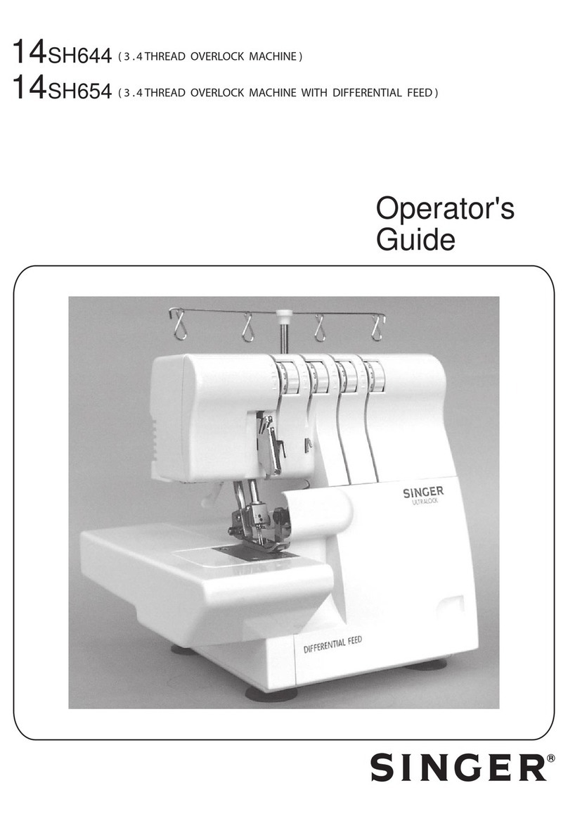
Singer 321C 131M-04 User manual

High
Speed
Overlock
Machine
73
7
M—04
243M—24
/
TF
732M—075
244
M—24
733M—04
/TF
257
M—35
734M—04
257
M—55
24
7
M—24
/
25
257
H—56
®
Singer
is
a
registered
trademark
of
The
Singer
Company
Limited
or
its
affiliated
companies.
©
2009
Copyright
The
Singer
Company
Limited

1.1
Important
Safety
Instructions
1
1.2
Safe
Operation
2
2.1
Product
Description
3
2.2
Machine
Specification
4
2.3
Motor,
Motor
Pulley
and
Belt
4
3.1
Table
Cut-Out
Diagram
5
3.2
Machine
Installation
6
3.3
Lubrification
and
Oil
Drainage
8
9
9
3.4
Needle
Attachment
(or
Replacement)
3.5
MachineThreading
3.6
Thread
Tension
Adjustment
10
3.6.1
Tension
Nut
Adjustment
10
3.6.2
NeedleThread
Control
10
3.6.3
LooperThread
Control
11
3.6.4
Chain
LooperThread
Cam
Control
11
3.7
Adjusting
the
Differential
Feed
Rate
12
3.8
Stitch
Length
Adjustment
12
3.9
Parts
Relation
andTiming
13
3.9.1
Needle
and
Needle
Plate
13
3.9.2
Upper
Looper
(Spreader)
and
Needle
14
3.9.3
Lower
Looper
and
Needle
14
3.9.4
Upper
and
Lower
Loopers
15
3.9.5
Needle
and
Needle
Guard
15
3.9.6
Chain
Looper
and
Needle
15
—
4.1
Machine
Head
Cleaning
16
4.2
Oil
Change
and
Filter
Cleaning
16
4.3
Safety
Inspection
16

6.1
Frame
Components
20
6.2
Cloth
Plate
Components
22
6.3
Cover
Components
24
6.4
Main
Shaft
Components
26
6.5
Needle
Bar
Components
28
6.6
Thread
Guide
Components
30
6.7
Upper
Looper
Components
32
6.8
Lower
Looper
Components
34
6.9
Front
Looper
Components
35
6.10
Cam
Components
36
6.11
Differential
Feed
Components
38
6.12
Feed
Dog
Components
40
6.13
Trimming
Components
42
6.14
Presser
Foot
Components
44
6.15
Lubrication
Components
46
6.16
Feed
Snap
Components
48
6.17
Thread
Spool
Components
50
6.18
Plate
Row
Material
Components
52
6.19
Accessories
53

1.1
Important
Safety
Instructions
Important
When
using
the
machine,
basic
safety
procedures
must
be
followed.
Flead
with
attention
all
instructions
before
using
the
machine.
When
using
it,
understand
that
all
basic
safety
instructions
are
not
limited
to
the
following
items.
Read
all
instructions,
take
care
of
this
manual,
and
use
it
as
reference
when
necessary.
Safety
Instructions
0
Before
running
the
machine,
make
sure
all
relevant
safety
specifica-
tions
are
adequate
to
specifica-
tions
and
technical
standards
in
your
country.
0The
machine
should
not
be
run
without
its
safety
devices.
0
The
machine
should
only
be
oper-
ated
by
properly
trained
personnel.
0
For
your
safety,
goggles
must
be
used
While
running
the
machine.
0
Turn
off
or
unplug
the
machine
in
the
following
situations:
0
Passing
the
thread
by
the
nee-
dle
or
replacing
the
bobbin
or
looper.
0
Replacing
the
needle,
presser
foot,
throat
plate,
feed
dog
and
sliding
plate.
0
When
the
machine
is
in
main-
tenance.
0
When
the
operator
is
not
run-
ning
the
machine.
Oln
case
of
lubricant
oil
contact
with
the
eyes
or
skin,
wash
the
surface
with
plenty
of
icy
water.
In
case
of
ingestion,
seek
medical
help
immediately.
ORepair,
fitting
or
maintenance
should
only
be
performed
by
properly
trained
personnel.
0Maintenance
and
repair
on
elec-
tric
equipment
should
only
be
made
by
qualified
personnel.
If
any
electric
device
is
damaged,
the
machine
should
be
immedi-
ately
stopped.
0
Before
starting
the
machine
in
full
running,
a
test
must
be
conducted
to
assure
that
machine
and
opera-
tor
are
able
to
perform
the
task.
0
The
machine
should
not
be
placed
next
to
a
sound
source
as
an
ultra-
sonic
welding
machine
and
other
equipment.
0
The
machine
should
only
be
run
with
the
proper
electric
cable
and
connectors,
and
also
the
ad-
equate
grounding.
.
The
machine
should
only
be
used
to
sew
materials
as
indicated
in
its
instructions
manual,
and
indi-
cations
of
use
should
be
followed.
Singer
will
not
be
held
responsible
for
any
damage
caused
by
unau-
thorized
changes
in
the
product.
High
Speed
Overlook
Machine
|
Instructions
Manual
and
Parts
List
1

1.2
Safe
Operation
A0
To
avoid
the
risk
of
electric
shock,
do
not
open
the
motor
wiring
box
and
do
not
touch
the
components
assembled
inside
the
wiring
box.
0To
avoid
injuries
do
not
run
the
machine
without
the
belt
cover
or
in
case
any
other
safety
device
is
removed.
0To
avoid
possible
injuries
keep
fingers,
head,
and
clothes
far
from
wheel,
belt
and
motor
when
the
machine
is
running.
Nothing
should
be
placed
near
those
parts.
0To
avoid
injuries
never
put
your
0To
avoid
accidents
in
case
of
a
sudden
start
of
the
machine
al-
ways
turn
it
off
when
laying
it
down,
or
remove
the
belt
cover
and
the
belt.
Olf
your
machine
is
equipped
with
a
servomotor,
it
does
not
make
noises
while
being
driven.
To
avoid
a
possible
accident
caused
by
an
unexpected
start,
bev
sure
the
ma-
chine
is
turned
off.
0To
avoid
electric,
do
not
run
the
machine
without
proper
ground-
Ing.
fingers
next
to
the
loopers
when
A'TO
minimize
the
risk
of
accidents
the
machine
is
running.
0The
shuttle
whirls
at
high
speed
while
the
machine
is
running. To
avoid
hand
injuries,
keep
them
away
from
the
shuttle
while
the
machine
is
running.
Turn
off
the
machine
to
replace
the
bobbin.
0
To
avoid
possible
injuries
be
care-
ful
when
putting
down
or
lifting
the
machine
head.
or
damages
in
electric
compo-
nents
caused
by
electric
discharge
turn
the
machine
off
before
un-
plugging
it.
OCIean
the
machine
periodically.
High
Speed
Overlook
Machine
|
Instructions
Manual
and
Parts
List
2

2
1
High
Speed
Overlock
Machine
I
Product
Description
High
Speed
Overlock
Machine
|
Instructions
Manual
and
Parts
List
3

2.2
Machine
Specification
9"
o
.0"
o
.0"
o
N
I
0
Clutch
motor
1/2
HP
(400W)
high
2
3
Speed
(2
poles)
l
Motor,
Motor
'
Belt
type
M
Pulley
and
Belt
90
i
95
i
100
i
105
i
110
i
115
High
Speed
Overlock
Machine
|
Instructions
Manual
and
Parts
List
4

3.1
Table
Cut-Out
Diagram
65]—
214
V
259
J—
305
J—
442
L
540
V
4001—
—
433
A
300
A
269
258
Figure
1
289
359
469
537
595
1200
High
Speed
Overlock
Machine
|
Instructions
Manual
and
Parts
List
(2)13
¢27

3
2
Install
the
machine
support
compo-
the
needle
bed
surface
to
the
table
I
nents
and
the
residues
cam
as
indi-
top
is
100mm.
For
inserted
assem-
_
cated
on
figure
2.
In
case
ofsemi-in-
bly
the
distance
is
about
5.0mm.
maChme
serted
assembly
the
distance
from
Installation
Figure
2
High
Speed
Overlook
Machine
|
Instructions
Manual
and
Parts
List
6

port
base.
the
right
side
and
the
pedal
of
the
3
2
Set
the
machine
head
on
the
sup-
Install
the
friction
motor
pedal
at
I
presser
lifter
at
the
left
side.
-
Connect
the
machine
Wheel
to
the
maChlne
motor
With
the
belt.
Be
sure
the
motor
is
clockwise
di-
Installation
-
Adjust
the
belt
tension
so
that
there
rected,
referred
to
figure
3'
is
a
gap
of
about
20
mm
when
the
center
of
belt
is
pressured.
Set
the
belt
cover
according
to
fig-
ure
4.
Figure4
High
Speed
Overlook
Machine
|
Instructions
Manual
and
Parts
List
7

3.3
Lubrication
and
Oil
Drainage
Important
As
this
is
a
high
speed
machine,
DO
NOT
run the
machine
before
oiling
and
assuring
the
direction
of
motor
rotation.
Remove
the
oil
flow
sight
win-
dow
14’
and
fill
with
the
lubricant
oil
(Singer
Oil),
until
the
indicator
of
the
oil
level
is
between
the
two
lines
of
the
oil
level
sight
window
’3’.
After
that,
put
back
the
oil
flow
window
’A’
and
squeeze
it.
When
using
the
machine
for
the
first
time,
or
a
machine
that
has
not
been
used
for
some
time,
oil
the
needle
bar
top,
the
guides
and
loopers
before
running
it.
A
new
machine
should
be
run
at
80%
maximum
speed
on
the
first
four
weeks.
After
this
initial
cycle,
Figure
5
replace
the
oil
and
from
then
on
the
machine
can
be
used
at
maxi-
mum
speed.
To
preserve
the
machine,
change
the
oil
after
four
weeks
of
use.
After
that
the
oil
must
be
changed
every
four
months.
To
change
the
oil
sim-
ply
remove
the
screw
’0’
indicated
on
figure
6.
After
draining
the
oil,
replace
the
screw
and
complete
the
machine
with
new
oil.
This
machine
has
an
oil
filter
(fig-
ure
6)
that
must
be
cleaned
every
month
or
changed
as
needed.
High
Speed
Overlook
Machine
|
Instructions
Manual
and
Parts
List
8

Use
needle
Singer
6120-06.
|—
—|
3.
4
Release
screw
’1’
as
indicated
on
W
Needle
figure
7
and
put
(or
Withdraw
the
_
old
needle).
AflaChment
I
It
th
dl
'th
th
I
tt
d
nse
e
nee
e
WI
e
s
o
urne
(or
Replacement)
to
the
back
side
and
push
it
up
until
the
bar
end.
Tighten
screw
’1.’
7
Figure
7
3
5
For
five
thread
machine
For
three
/
four
thread
machine
I
Machine
Threading
Important
Refer
to
the
sewing
type
you
need
for
correct
threading.
Any
incorrect
threading
may
cause
thread
brake,
uneven
stitches
or
skip
stitches.
High
Speed
Overlook
Machine
|
Instructions
Manual
and
Parts
List
9

3.6
Thread
Tension
Adjustment
Important
The
thread
tension
should
be
adjusted
according
to
the
type
and
thickness
of
cloth,
thread,
sewing
Width,
stitch
length
and
others.
Therefore,
the
pressure
on
the
Tension
Buttons
or
Thread
Guides
should
be
individually
adjusted
for
each
case.
3.6.
1
Tension
Nut
Adjustment
3.6.2
Needle
Thread
Control
Note
The
signal
(+)
increases
the
tension
in
the
thread.
The
signal
(-)
reduces
the
tension
of
the
thread.
Tension
Nut
3:
controls
the
thread
in
the
right
looper
The
following
adjustments
are
re-
lated
to
figure
10.
Tension
Nut
4:
controls
the
thread
in
the
left
looper
Tension
Nut
1:
controls
the
needle
thread
or
the
left
thread
in
case
of
two
need/es.
Tension
Nut
5:
controls
the
thread
of
the
safety
stitch.
Tension
Nut
2:
controls
the
thread
in
the
right
needle.
\/
Figure
10
For
all
types
ofstitch
504,
512
or
514,
move
down
the
guides
’1’and
’2’.
For
the
types
of
stitch
503
and
505,
move
the
guides
’1’
and
’2’
to
the
highest
point.
High
Speed
Overlook
Machine
|
Instructions
Manual
and
Parts
List
10

3.6.3
Looper
Thread
Control
Note
The
signal
(+)
means
more
thread
and
(-l
means
less
thread.
3.6.4
Chain
Looper
Thread
Cam
Control
For
the
type
ofstitch
512,
when
Ad-
For
the
type
of
stitch
503
and
505,
just
guide
’1’and
’2’as
follows
the
move
the
guides
to
the
lowest
looper
on
the
right
is
at
the
left
far
point
and
adjust
’1’
and
’2’
in
level
end,
adjust
’1’
and
’2’
in
level
with
with
the
continuous
line.
the
dotted
mark,
as
on
figure
12.
Adjust
guide
,3,“
follows:
0
Position
14’:
for
stretchy
thread
0
Position
’B’:
for
seaming
and
blind
stitch
hemming
0
Position
’0’:
stitch
type
512
Adjust
guide
’4’
as
follows:
0
Position
’0’:
for
stretchy
thread
0
Position
’E’:
for
seaming
and
blind
stitch
hemming.
Figure
12
When
the
needle
is
on
high
posi-
tion,
mark
14’
must
be
aligned
with
the
thread
guide
bracket
’1’,
as
shown
on
figure
13.
Release
screw
’2’
and
the
thread
cam
’3’.
Turn
it
clockwise
for
quick
release
of
thread
through
the
cam.
Figure
13
High
Speed
Overlook
Machine
|
Instructions
Manual
and
Parts
List
11

3.7
Adjusting
the
Differential
Feed
Rate
Note
When
the
surface
of
level
’3’adjustment
is
on
scale
2,
the
differential
adjustment
is
l
.'
l,
and
if
it
is
on
the
scale,
its
proportion
may
be
adjusted
up
to
7
.'
0.7
3.8
Stitch
Length
Adjustment
Important
The
stitch
length
adjustment
is
made
according
to
the
sewing
fabric,
differential
feed
ratio
and
other
factors.
Adjustment
of
the
differential
is
the
dragging
proportion
between
the
main
feed
dog
and
differencial
feed
dog.
When
the
movement
of
main
feed
dog
is
less
than
that
of
the
differencial
feed
dog,
the
cloth
will
be
frilled
during
sewing.
Otherwise,
the
cloth
will
be
stretched.
Press
button
to
the
end
and
keep
it
pressed
as
shown
on
figure
15.
Turn
the
wheel
until
we
have
the
desired
stitch
length.
It
is
shown
on
the
wheel
scale.
Release
nut
’1’on
figure
14,
and
turn
screw
’2’
clockwise
to
streching
the
cloth
or
counter
clockwise
to
shrink
it.
Retightend
the
nut
’1’.
Figure
14
/
Figure
15
1.
0
1.
4
1.
7
2.
5
2.3
3.1
3.9
4.7
5.4
5.9
0.9
1.2 1.5 1.8
2.1
1.0
High
Speed
Overlock
Machine
|
Instructions
Manual
and
Parts
List
12

3.9
Parts
Relation
and
Timing
3.9.
1
Needle
and
Needle
Plate
When
needle
at
the
highest
posi-
tion,
distance
14’
between
needle
point
(the
left
needle
if
there
are
two
needles)
and
needle
plate
is
9.5
to
9.7
mm
for
standard
adjust-
ment,
or
10.8
to
11.0
mm
for
spe-
cific
cases.
Each
needle
should
be
centralized
over
each
hole
in
the
needle
plate.
The
right
needle
must
be about
0.2
to
0.3
mm
ahead
the
left
needle.
Distance
between
needle
point
(
the
right
needle
if
there
are
two
nee-
dles)
and
the
front
part
of
the
hole
in
the
needle
plate
or
presser
foot
is
1.2
mm.
A:
9,5
-
9,7
mm
High
Lift:
10,8
-
11,0
mm
Release
screw
’1:
as
shown
on
fig-
ure
16.
Turn
the
wheel
to
see
if
needle
is
centralized
at
every
hole
of
the
needle
plate.
Release
screw
’2’
to
adjust
needle
holder.
Turn
the
wheel
to
move
needle
to
the
highest
position
and
move
nee-
dle
bar
until
the
height
is
correctly
adjusted.
Tighten
screws
’1’and
’2’.
Figure
16
High
Speed
Overlook
Machine
|
Instructions
Manual
and
Parts
List
13

3.9.2
Upper
Looper
(Spreader)
and
Needle
3.9.3
Lower
Looper
and
Needle
When
the
right
looper
moves
to
the
needle.
For
two
needles,
the
dis-
far
left
end, distance
fl’between
the
tance
’B’
is
5.5
to
6.0
mm
from
the
looper
point
and
the
center
line
of
left
need/e,
as
shown
on
figure
12
the
needle
is
4.5
to
5.0
mm
for
one
Figure
17
When
the
lower
looper
moves
to
When
the
lower
looper
moves
to
the
extremly
left,
the
distance
14’
the
center
line
of
needle
(left
nee-
between
looper
point
and
center
die,
if
two
needles),
the
gap
be-
line
of
the
needle
(left
needle,
if
tween
needle
and
looper
is
from
0
two
needles)
is
from
3.4
to
3.6
mm,
to
0.05
mm,
as
shown
on
figure
19.
for
high
lift
machines,
as
shown
on
figure
18. E
E
(m
0
©
”8’
:i;—:
i—f_
Figure
19
A
Figure
18
High
Speed
Overlook
Machine
|
Instructions
Manual
and
Parts
List
14

3.9.4
Upper
and
Lower
Loopers
3.9.5
Needle
and
Needle
Guard
3.9.6
Chain
Looper
and
Needle
When
the
upper
and
lower
Ioopers
are
crossed,
the
distance
is
0.2
mm
for
’A’
and
0.5
mm
for
’B’,
accord-
ing
figure
20.
When
the
looper
point
is
on
the
side
opposite
to
the
center
line
of
the
needle
(left
needle
if
there
are
two
needles),
space
between
nee-
dle
and
rear
needle
guard
of
14’
is
0
mm.
When
needle
moves
to
the
lowest
position,
space
between
needle
and
front
needle
guard
of
’B’is
from
0.15
to
0.20
mm,
accord-
ing
to
figure
21.
The
safety
looper
should
be
fixed
in
a
position
lower
than
this
support.
And
when
it
moves
to
the
left
far
end,
the
distance
between
the
loop-
er
point
and
the
center
line
ofneedle
is
2.5
mm,
according
to
figure
22.
0.5
A
0.2
.
//
__
/
/_'\_
Figure
20
0.0
A
0.15
-
0.20
mm
In!“
M?
Figure
21
Figure
22
High
Speed
Overlook
Machine
|
Instructions
Manual
and
Parts
List
15

E
4.1
Machine
Head
Cleaning
4.2
Oil
Change
and
Filter
Cleaning
4.3
Safety
Inspection
Maintenance
Clean
the
machine
head
periodi-
cally
with
a
dry
soft
cloth
to
remove
the
excess
of
dust
in
the
head.
Do
not
use
any
kind
of
solvent
material
to
clean
the
surface.
If
the
machine
has
not
been
used
for
a
long
time, lubricate
the
superior
part
of
the
needle
bar,
guides
and
loopers
before
returning
to
opera-
tion.
Oil
should
be
changed
every
four
months.
When
changing
the
oil
fol-
low
instructions
on
item
3.3.
Frequently
check
if
all
safety
de-
vices
are
properly
installed
and
adjusted.
Check
all
screws
that
fix
and
hold
the
machine
head
that
should
be
properly
tight.
Check
and
be
sure
the
belt
is
not
excessively
worn
out
and
see
that
it
has
the
proper
tension.
Oil
filter
should
be
cleaned
every
month
or
replaced
for
a
new
one
as
necessary.
To
clean
the
filter
or
change
the
oil,
fol/ow
instruction
in
item
3.3.
Check
and
be
sure
there
is
no
mo-
tor
overheating
and
be
sure
that
the
cable
and
electric
connector
are
not
damaged.
High
Speed
Overlook
Machine
|
Instructions
Manual
and
Parts
List
16

Possible
Causes
H
Needle
installed
the
wrong
way.
Wrong
kind of
needle.
Damaged
needle.
Wrong
relation
with
needle
guards.
Wrong
relation
with
looper.
939199!“
plate
or the
presser
foot.
Needle
is
not
centralized
with
the
hole
at
the
needle
H
Low
quality
thread.
Thread
is
thicker
than
the
eye
of
the
needle.
Wrong
passage
of
thread.
Thread
tension
too
tight.
Needle
wrongly
set.
915-"!in
Thread
stand
wrongly
set.
Z
Needle
overheating.
8.
Tension
disk
or
guides
with
burrs
.
9.
Wrong
relation
of
needle
with
looper.
10.
Needle,
looper,
needle
plate
and
guides
have
burrs.
1.
Wrong
relation
of
needle
with
looper.
.
Wrong
passage
of
thread.
.
Inadequate
tension
of
thread.
2
3.
Needle
installed
the
wrong
way.
4
5
.
Point
of
looper
damaged.
6.
Needle
damaged.
Z
Wrong
installation
of
needle
guards.
1.
Wrong
threading.
2.
Thread
is
thicker
than
needle
hole.
3.
Wrong
thread
tension.
4.
Needle
thread
is
not
lubricated.
5.
Wrong
relation
of
needle
with
looper.
High
Speed
Overlock
Machine
|
Instructions
Manual
and
Parts
List
1
\l
This manual suits for next models
8
Table of contents
Other Singer Sewing Machine manuals

Singer
Singer 4522 User manual

Singer
Singer Feather Weight II User manual

Singer
Singer 212 User manual

Singer
Singer 991B3 User manual

Singer
Singer 2 User manual

Singer
Singer 591EUTT Manual

Singer
Singer 81-12 User manual

Singer
Singer 206K25 User manual

Singer
Singer 211U157A Setup guide

Singer
Singer 7225J Setup guide

Singer
Singer 111G157 Quick start guide

Singer
Singer 245-1 User manual

Singer
Singer 6233 User manual

Singer
Singer One Plus User manual

Singer
Singer 8770 CURVY User manual

Singer
Singer Scholastic 85SCH User manual

Singer
Singer 4443 User manual

Singer
Singer 46W Quick start guide

Singer
Singer WHITE User manual

Singer
Singer 17-25 User manual