CONTENTS
Page
INTRODUCTION · · · · ·
0-1
1
GENERAL
DESCRIPTION
· · · · · · · · ·
1-1
2
OPERATOR
CONTROL
PANEL
· · ·
2-1
3 INSTRUCTION
FORMAT.
3-1
Read
and
Write
Instructions
· · · · · .
3-1
Six-Character
Disc
Address
· · · · · ·
3-1
4
WroTE
OPERATIONS . . · · · · ·
4-1
5 READ OPERATIONS . . . · · · · · · · · ·
5-1
6
MULTI-PARTITION
CONSIDERATIONS .
6-1
7 TIMING CONSIDERATIONS • · ·
7-1
8
OPERATING
INSTRUCTIONS · · · . · ·
8-1
9 CONDITION CODE SUMMARY · · · · · · · . . · · .
9-1
ILLUSTRA
TIONS
1/72
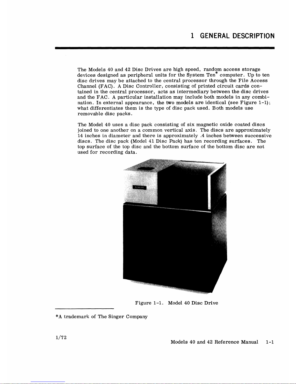
Figure
1-1.
Figure
2-1.
Figure
3-1.
Figure
7-1.
Figure
8-1.
Figure
8-2.
Figure
8-3.
Model
40
Disc
Drive
.
Operator
Control
Panel
.
Six-Character
Disc
Address
Disc
Sector
Layout
. • • • . • . • •
Top
View of a Model 41B
Disc
Pack
in
Its
Carrying
Case
.
Top
View
of
a Model 41A
Disc
Pack
in
Its
Carrying
Case.
Bottom
View
of
a
Model
41,
41A,
or
41B
Disc
Pack
in
Its
Carrying
Case
.
1-1
2-1
3-2
7-2
8-1
8-2
8-3
Models
40
and
42
Reference
Manual
iii