Singmai Electronics DB09 User manual

DB09 User Manual Revision 0.1 Page 1 of 11
DB09
Video Receiver
User Manual
Revision 0.1
27th September 2023

DB09 User Manual Revision 0.1 Page 2 of 11
Revisions
Date
Revisions
Version
27-09-2023
First draft
0.1

DB09 User Manual Revision 0.1 Page 3 of 11
Contents
Revisions...................................................................................................................................................2
Contents ...................................................................................................................................................3
Figures ......................................................................................................................................................3
1. Introduction ....................................................................................................................................4
2. Quick start guide.............................................................................................................................5
3. DB09 Technical Details....................................................................................................................6
4. Specification....................................................................................................................................9
Appendix A: AC-DC adaptor....................................................................................................................10
Figures
Figure 1 DB09 Connections. .....................................................................................................................5
Figure 2 DB09 Block diagram....................................................................................................................6
Figure 3 Frequency response for various coaxial cable lengths. ..............................................................7
Figure 4 Frequency response for various UTP cable lengths....................................................................7
Figure 5 Output filter frequency response (SD setting)............................................................................8
Figure 6 Output filter frequency response (HD setting)...........................................................................8
Figure 7 Power supply specification: electrical. .....................................................................................10
Figure 8 Power supply specification: mechanical...................................................................................11

DB09 User Manual Revision 0.1 Page 4 of 11
1. Introduction
DB09 is a standard definition (SD) / high definition (HD) video receiver. It accepts analogue video from
either twisted pair (differential) or coaxial cable and compensates for long cable runs using an
adjustable matching filter. Its 75MHz video bandwidth means it can accept NTSC, PAL, 960H, AHD,
HD-CVI and HD-TVI video. The video is DC restored and two buffered and filtered single ended
outputs are provided.
DB09 requires 12VDC which is provided via the supplied AC-DC converter.
DB09 User Manual Revision 0.1 Page 5 of 11
2. Quick start guide
Connect the DB09 to the supplied AC/DC adaptor. Fit the appropriate blades to the adaptor for your
country. Blades are supplied for North America, Europe, UK, China and Australia. The adaptor accepts
AC between 90 and 264VAC –the full specification is provided in Appendix A.
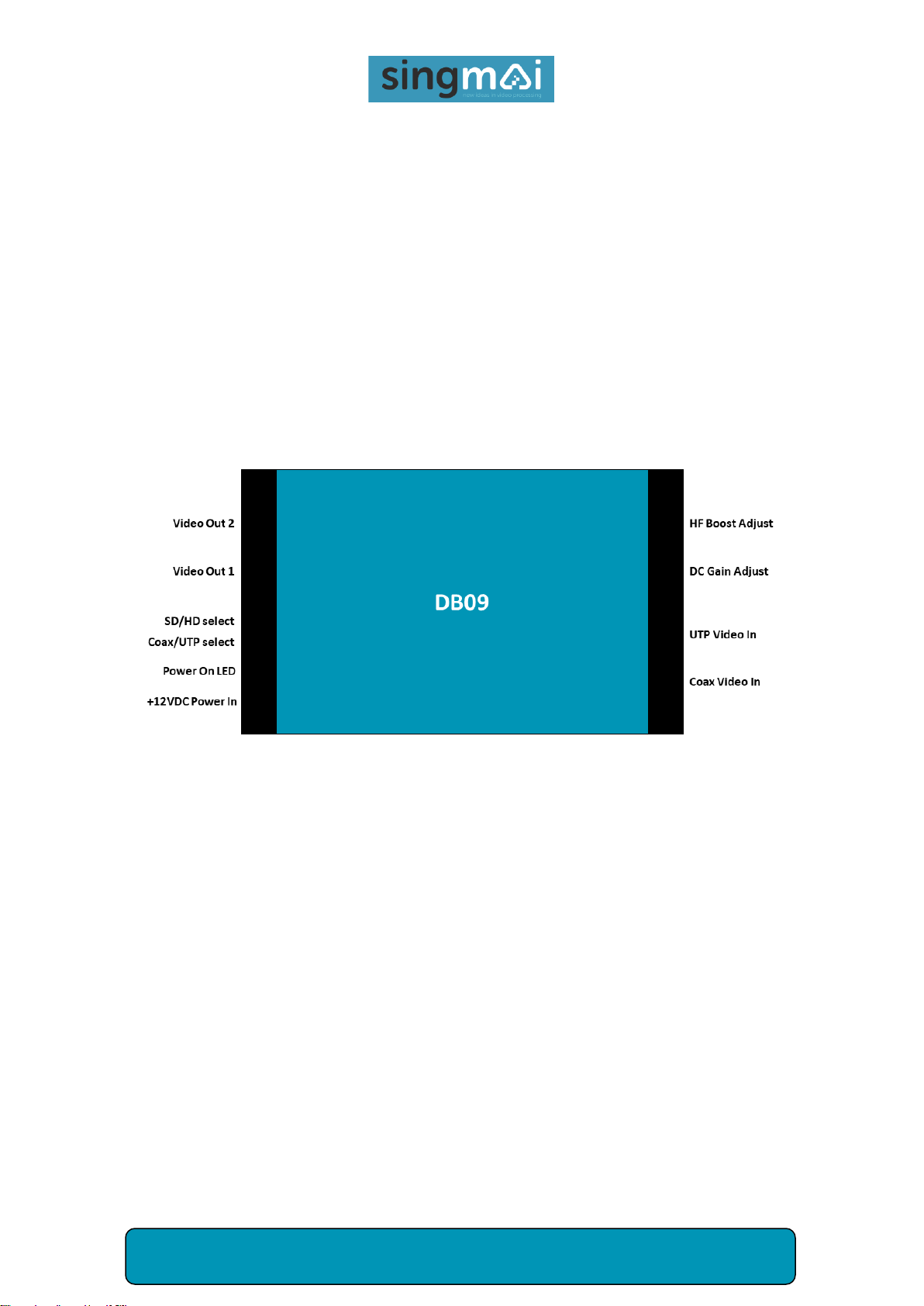
The connections to the DB09 are shown in Figure 1.
Connect the 12VDC jack from the adaptor to the +12VDC ‘Power in’ socket on the DB09. The ‘Power
On’LED should light up blue.
Connect your video input to either the UTP (RJ-45) connector or the coaxial video input (BNC).
Switching between the two inputs is by the Coax (switch UP) / UTP (switch DOWN) switch. You can
connect both UTP and coaxial inputs at the same time if required.
Figure 1 DB09 Connections.
The DB09 provides two independent video outputs. The single ended outputs should be terminated in
75Ω. The outputs are filtered and buffered. The SD/HD switch selects the output filter bandwidth,
reducing any out of band noise. The SD selection (switch UP) passes NTSC/PAL or 960H video, the HD
selection (switch DOWN) is for analogue HD such as AHD.
Two adjustments are available to compensate for cable loss. The DC Gain control allows an adjustable
gain that affects all frequencies equally and is designed to compensate for the DC cable loss. The HF
Boost control boosts the high frequencies of the video input using a filter that is the inverse of the
cable high frequency loss. The response of this filter is set using the Coax (for coaxial cable) / UTP (for
UTP cable) switch. The filter can accurately compensate for up to 300m of UTP cable and 200m of
coaxial cable. Longer distances can be compensated for but with less accuracy.
DB09 User Manual Revision 0.1 Page 6 of 11
3. DB09 Technical Details
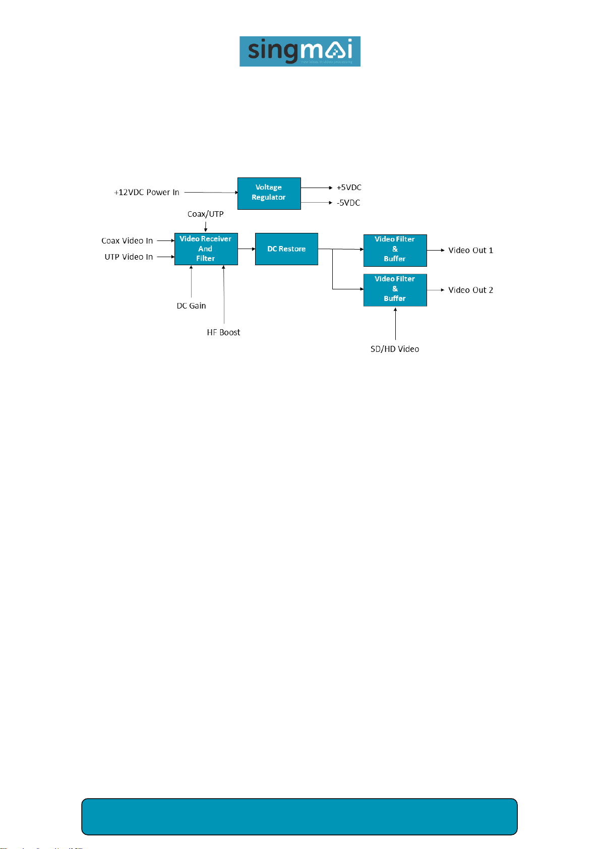
A simplified block diagram of the DB09 is shown in Figure 2.
Figure 2 DB09 Block diagram.
The +12VDC from the AC/DC power adaptor is filtered and protected from over-range or reverse
polarity inputs. The 12VDC input is then regulated to provide clean ±5VDC for the module.
The coaxial video input is pseudo-differentially received which reduces hum pickup over long cable
runs. The video input is terminated by 75Ωand is protected from out-of-range inputs or glitches.
The UTP video input is differentially received, terminated in 100Ωand is protected from out-of-range
inputs or glitches. Pin 1 of the RJ-45 input is the positive video input and pin 2 is the negative video
input. The other pins are not connected.
The selected video input is then passed through the cable compensating filters. The broadband gain
and high frequency boost are user adjustable. Figures 3 and 4 show the expected results for different
lengths of coaxial and UTP cable.

DB09 User Manual Revision 0.1 Page 7 of 11
Figure 3 Frequency response for various coaxial cable lengths.
Figure 4 Frequency response for various UTP cable lengths.
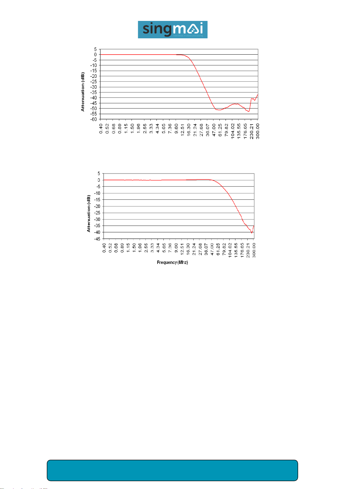
The output from the compensating filter is then DC restored and filtered and buffered. The output
filter helps to reduce noise and can be set to either SD or HD video. The filter responses are shown in
Figures 5 and 6. This output filter sets the overall frequency response of the DB09.
DB09 User Manual Revision 0.1 Page 8 of 11
Figure 5 Output filter frequency response (SD setting).
Figure 6 Output filter frequency response (HD setting).
The buffer amplifies the video by a gain x2 (6dB) so that it can drive a series 75Ωresistor. Each output
must be terminated in 75Ωfor the DB09 to have the correct gain. Because each output is individually
buffered either or both outputs maybe be connected –any unused output may be left unconnected.

DB09 User Manual Revision 0.1 Page 9 of 11
4. Specification
Power: +9-14V (+12VDC nominal) @ ~120mA (all outputs driven).
Dimensions: 120mm x 78mm x 27mm.
Video input: NTSC-M / PAL /SECAM, NTSC / PAL 960H, AHD, HD-CVI, HD-TVI.
75Ω input impedance (coaxial).
100Ω input Impedance (UTP).
1V pk-pk nominal input. Maximum input before clipping 1.6V pk-pk.
Luma bandwidth: 9.0MHz ± 0.5dB (SD mode). 50.0MHz ± 0.5dB (HD mode).
Gain controls set to minimum.
Gain: 0dB ± 0.5dB. Gain controls set to minimum.
Differential gain/phase: <1%, <1°. (NTSC/PAL). Gain controls set to minimum.
K-factor: <1%. (NTSC/PAL). Gain controls set to minimum.
Group delay: ±10ns.
Operating temperature: -10 –+40 degC.

DB09 User Manual Revision 0.1 Page 10 of 11
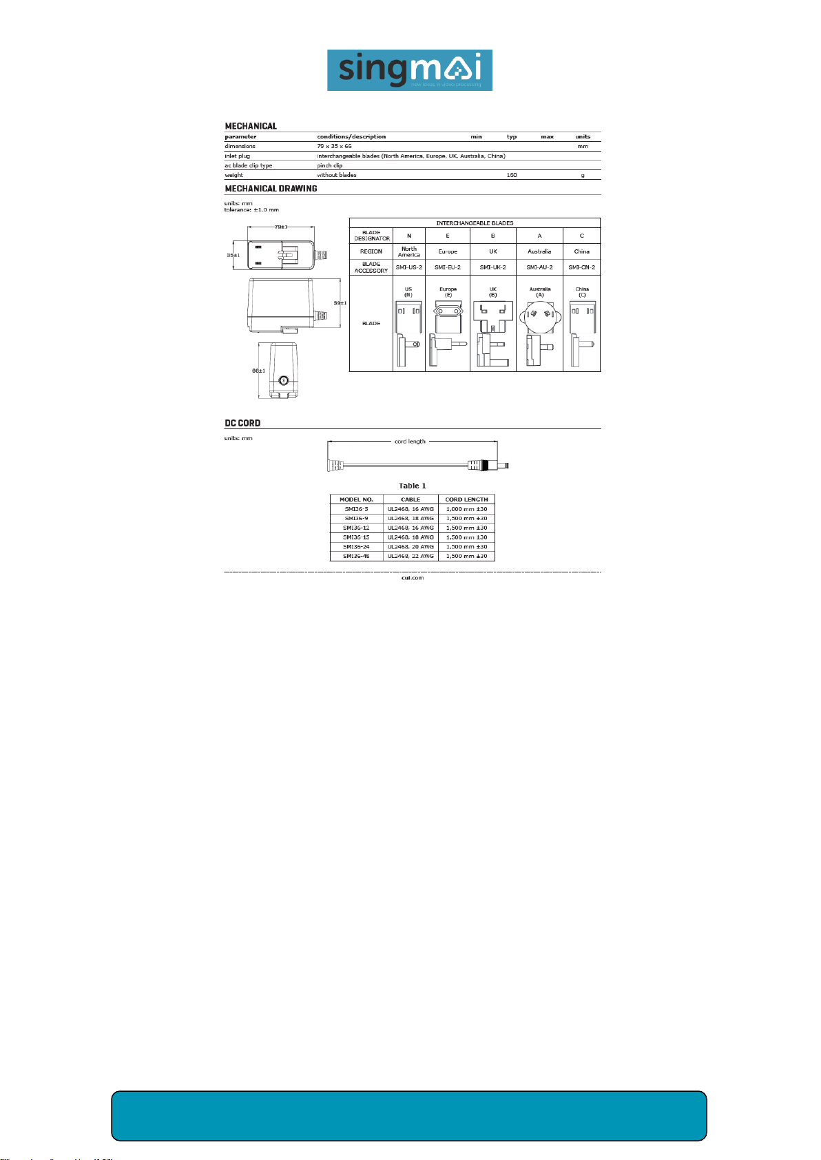
Appendix A: AC-DC adaptor
The specification for the supplied AC-DC adaptor is shown in Figures 7 and 8.
Figure 7 Power supply specification: electrical.
DB09 User Manual Revision 0.1 Page 11 of 11
Figure 8 Power supply specification: mechanical.
Table of contents


