SinoAero 1.8m Flyaway User manual

SinoAero 1.8M Flyaway Antenna
Installation Instructions(C and Ku band Applicable)
1 The antenna property
1.1 Electric property
1.1.1 frequency:Transmission: 5.925~6.425GHz
Reception: 3.7~4.2GHz
1.1.2 Gain:Transmission: 39.5 dBi
Reception:35.7 dBi
1.1.3.Beamwidth( 3dB):Tansmission:1.89°
Reception:2.95°
1.1.4.Sidelobe envelope: 29-25LOG(θ) dBi(1°≤θ≤20°)
1.1.5 Power capacity: 1000W
1.1.6 Interface: Transmission: CPR-137G/F
Reception: CPR-229G/F
1.1.7 Cross polarization isolation:≥35dB(Axial)
1.1.8 Voltage standing wave ratio:≤1.25:1(reception、transmission)
1.1.9 TX-RX isolation:>85dB
1.2 Mechanical features
1.2.1 Antenna configuration form:azimuth—elevation configuration form
1.2.2 The coaxial duplexer:disassemble coaxial duplexer
1.2.3 The driving mode: manual
1.2.4 Azimuth range: ±90°
Elevationrange:0°~90°
1.2.5 Operational Wind Speed:20m/s
1.2.6 Anti-Seismic Capacity:Horizontal: 0.3G’s
Vertical: 0.1G’s
1.2.7 Temperature:-30~+55
1.2.9 Gross weight:80Kg
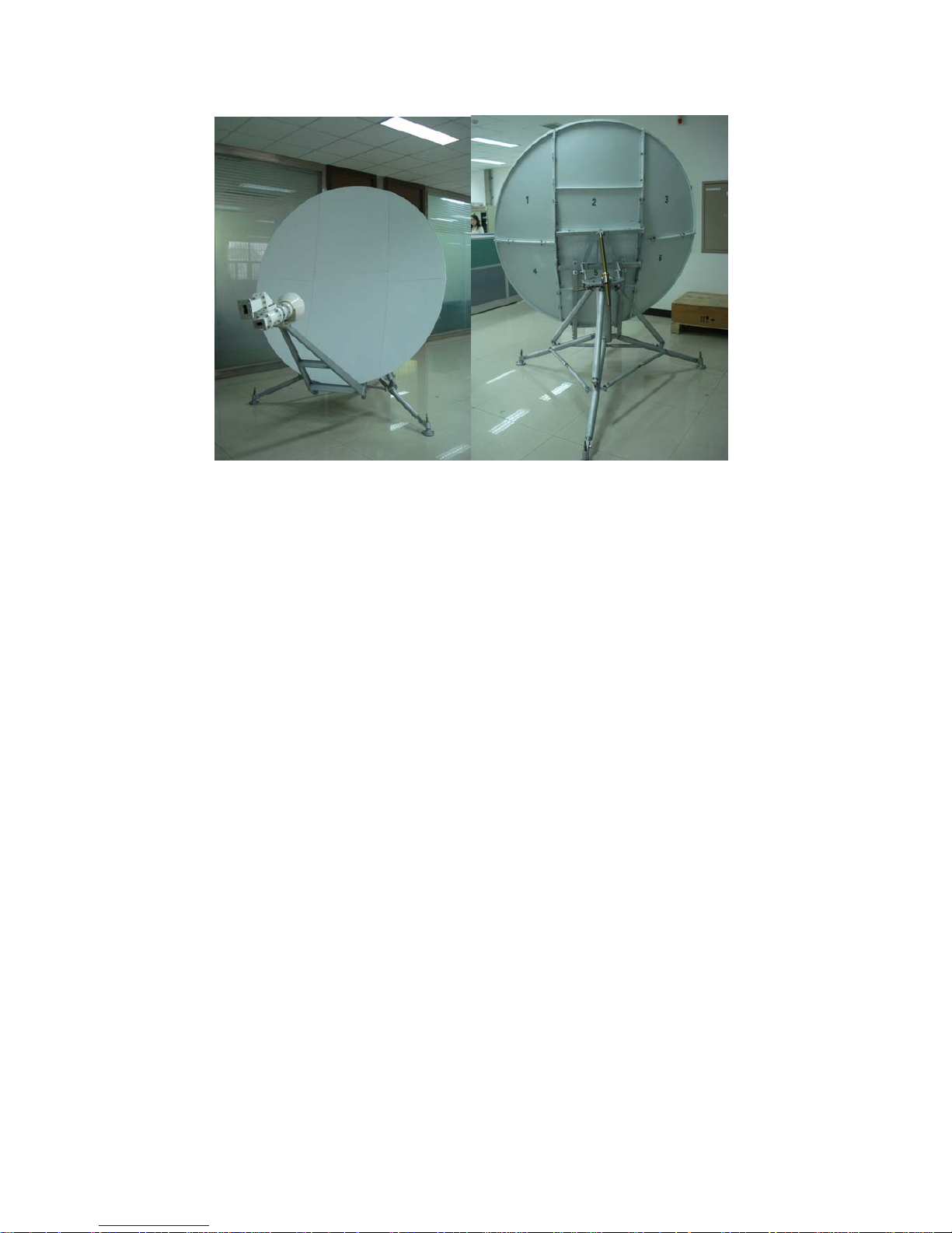
2 Antenna composition
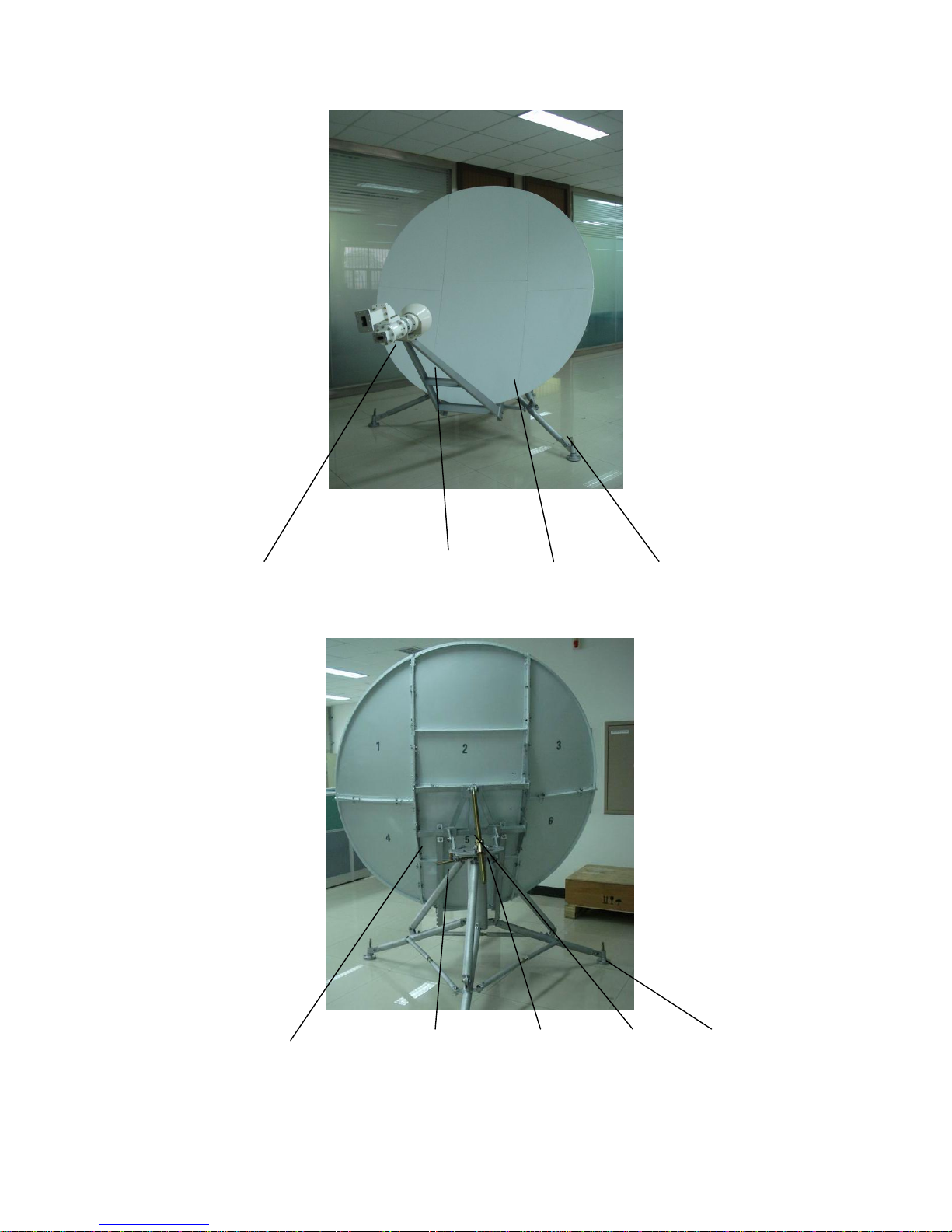
1 2 3 4
1 The coaxial duplexer 2 The feed bracket 3 The panels (six) 4 The tripod
Fig.1
1 2 3 4 5
1 The reflector bracket 2 The azimuth adjustment mechanism 3 The
azimuth Turntable 4 The elevation adjustment mechanism 5Thefoundationdish
Fig. 2

As shown in Figure1 and Figure 2(The configuration of the antenna), the antenna
is composed of the feed system(the feed, the coaxial duplexer, the feed bracket),the
reflector(the main reflector, the reflector bracket),the and the foundation(the
elevation adjustment mechanism, the azimuth Turntable, the azimuth Turntable, the
tripod, the foundation dish).
3 The Installation
3.1 The calculation of the antenna angle
The calculation of the antenna azimuth angle(AZ):
()
)
sin
(
(180
e
e
LLtg
arctgAZ
φ
)
卫星 −
+= ο
The calculation of the antenna elevation angle(EL):
(
)
()
[]
()
)
coscos(1
152266.0coscos(
(5.0
2
ee
ee
LL
LL
arctgEL
φ
φ
)
)
卫星
卫星
−−
−
−
=
The calculation of the antenna polarization angle(pol):
()
)
sin(
(
e
e
tg LL
arctgpol
φ
)
卫星 −
=
Remarks:
—The Satellite longitude
卫星
L
e
L—The earth longitude
e
φ
—The earth Latitude
3.2 The relation of the feed offset angle and the elevation angle
—the elevation angle of the antenna
EL
θ
—the elevation of the feed bracket
φ
—the feed offset angle is 10°
The formula of the Calculation :
φ
θ
+
=
EL
3.3 The installation of the antenna:
3.3.1 The installation tool:the wrench(Adjustable):one set. the specification:the extent:
200mm. the longest hatch: B=24mm} Remarks: the user can prepare three
specifications fixation wrenchs(16×18、22×24、12×14)for the installation.
The fixation wrenchs: two set . The specification: 8×10.The hammer: one set.
3.3.2 Installation Steps
1) First ,open the casing box ,then take the feed system, the reflector,the foundation
dish ,the standard screw and the others out from the casing box.
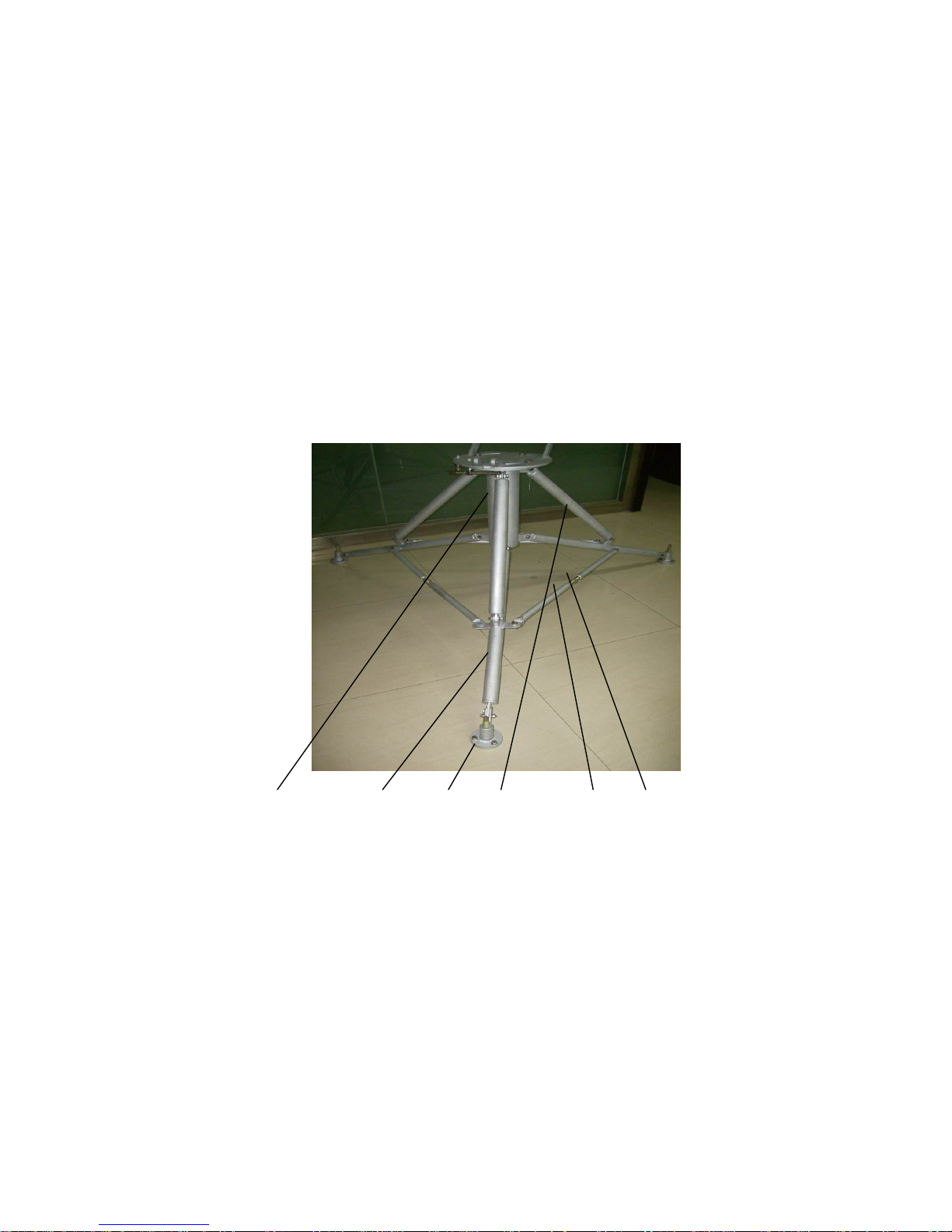
2) The connection of the foundation:First, connect each end of the three main
knightheads to the the main pole which is under the the azimuth Turntable,and the
other end connect with the foundation dish. and then connect the main pole to the
main knighthead with the oblique knighthead. then connect the landscape orientation
knighthead to the main knighthead.(notice: the landscape orientation knighthead is
adjustable by the adjustable screw thread. At the end , install the azimuth adjustment
mechanism and the elevation adjustment mechanism. (see Fig. 3)
1 2 3 4 5 6
1. the main pole 2 .the main knighthead 3 .The foundation dish
4. the oblique knighthead 5 .the landscape orientation knighthead
6 .the adjustable screw thread
fig.3 the configuration of the foundation
Screw down all the nut after all the part of the foundation is connected.and then
adjust the foundation dish by the box and needle which is in the azimuth Turntable till
the bleb is in the middle of the box and needle.at last,adjust the length of the
landscape orientation knighthead in order to fix the foundation.
3) The connection of the reflector bracket and the feed bracket:

first, connect longitudinal bracket to the the feed bracket by eight M10 bolt.
and then connect the the landscape orientation bracket to the longitudinal bracket by
four M10 bolt.then connect the abdomen board to the one side of the landscape
orientation bracket by twelve bolt,the other side is same. The function of the abdomen
board is that connect the reflector bracket to the reflector. At last,connect the bracket
to the ear-support which is in the foundation. (see Fig. 4).
1 2 3 4 5
1 the ear-support of the elevation 2 the abdomen board 3the landscape orientation
bracket 4 the longitudinal bracket 5 the feed bracket
Fig.4 the configuration of the bracket
4) The installation of the reflector: assemble the panels (the reflector)by the marks
that 1-4,2-5,3-6. Assemble these antenna panels with the bolt that is in the
panels on the ground, then connect the panel(2-5) which is in the middle of the
reflector to the bracket. Connect the abdomen board to the reflector by the bolt that is
on the abdomen board. (see Fig. 2).
5) The installation of the coaxial duplexer and the feed: connect the feed and the
coaxial duplexer to the transition Chassis by the Semicircle Clasp. The polarization
angle can adjust when the Semicircle Clasp is loosened, then connect the
transition Chassis to the feed bracket with four M6 bolt. (see Fig. 5).

1 2 3 4 5
1 The reflector bracket 2 Semicircle Clasp 3 Transition Chassis
4 The feed 5 The feed bracket
Fig.5 the configuration of the feed system
6) Antenna adjustment
a. Adjustment of antenna elevation angle:
According to calculated antenna elevation angle,preset antenna reflector to calculated
position by rotating large knob of elevation lead screw (refer to elevation scale), then
trim elevation lead screw through knob to align antenna toward satellite.
b.Adjustment of antenna azimuth angle:
According to calculated antenna azimuth angle, approximately preset antenna to
calculated azimuth angle, unscrew one large knob under tripod upright, then, referring
to the scale, rotate large knob of azimuth lead screw to align antenna toward satellite.
Adjust antenna to get optimum reception effect by azimuth & elevation adjustment,
then screw down large knob on tripod upright to prevent antenna from shake during
its operation.
4 The maintenance of the antenna
4.1 Fasten the foundation with the steel wire that the type is bigger then ∅4.One
side connect the foundation, the other side connect the anchor. Collections the antenna
when the wind is bigger then the working wind.
4.2 Smear the lubricate Grease to protect the bolt when the antenna is not used.
4.3 It should be spray-paint when the antenna’s reflector is worked two years.The
bracket and the foundation should besmear gray paint to protect when they are
damaged.
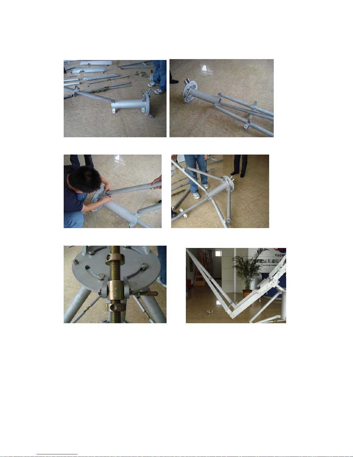
The step of the installation
The installation of the foundation
the installation of the oblique knighthead
the installation of the the azimuth thread theinstallation of the
bracket and the feed bracket
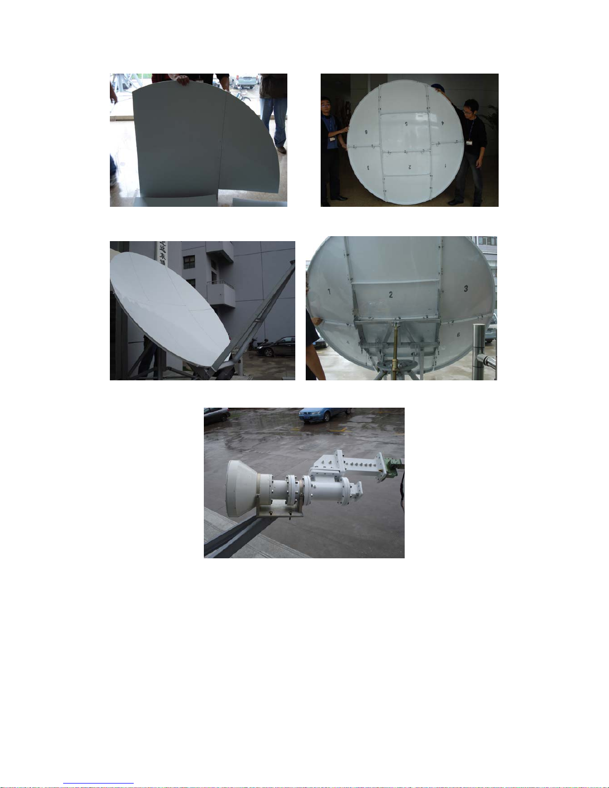
the installation of the main reflector
put the reflector on the bracket of the antenna
the installation of the feed and the coaxial duplexer
the overall figure of the antenna
Popular Antenna manuals by other brands


Winegard
Winegard Sensar HV CC-25HV Installation & operation manual

ESCO Technologies
ESCO Technologies ETS LINDGREN 3158 user manual

TRENDnet
TRENDnet TEW-AI07OB Quick installation guide

Hy-Gain
Hy-Gain TH-11DX instruction manual

Furuno
Furuno AT-1575 Replacement instructions

Solid Signal
Solid Signal ColorKing 5886 Assembly guide


