Sioux Tools 208054 Parts list manual

Centrifugal Fans
Owner’s Parts and Instruction Manual
Centrifugal- 60Hz
HP 1750rpm (Standard Low Speed)
208V-230V 460V
1-Phase 3-Phase 3-Phase
5 208054 208052 208053
7.5 208059 208057 208058
10 208064 208062 208063
15 208184 208069 208070
20 208075 208076
25 208081 208082
30 208087 208088
40 208093
50 208096
60 208098
Note: 60hp less controls
Sioux Steel Company
Sioux Falls, South Dakota 57101
800-557-4689
Manual No. 208370
KAG/2-5-2016
Rev E/02-01-2018/ECN 18-023

2

3
CONTENTS
Contents……………………………………….….. 3
Safety……………………………………………... 4-9
Pre-Installation Requirements...……………….. 10
Installation……………………………………….. 11-13
Electrical Installation……………………………. 14-15
Final Check & Test Run………………………… 16
Electrical Diagrams……………………………… 17-18
Operation………………………………………… 19
Maintenance……………………………………… 20
Wheel and Motor Removal/Installation………… 21
Troubleshooting Guide…………………………... 22-24
Specifications…………………………………….. 25
Discharge Bolt Pattern………………………….. 26
Centrifugal Fan Parts Assemblies……………… 27
Starter Box (C3 Controls)……………………… 28
Starter Box (TC Controls)……………………… 29
Warranty………………………………………… 30

4
READ AND SAVE THESE INSTRUCTIONS
GENERAL SAFETY STATEMENTS
Thank you for choosing a Sioux Steel Company product. It is designed to perform and serve you for many
years.
It is the goal of Sioux Steel Company to improve our products whenever it is possible and practical to do
so. Sioux Steel Company reserves the right to change, improve, and modify products at any time without
obligation to make changes, improvements, and modifications on previously sold equipment.
Safety is Sioux Steel Company’s main concern for you and those who are associated with the grain
handling equipment. This manual is written to help you understand safe operating procedures, and some of
the problems that may be encountered by operator or other personnel.
It is your responsibility as owner/operator to know what requirements, hazards, and precautions exist, and
to inform all personnel associated with the equipment. Any alterations to equipment are strictly forbidden.
Such alterations may result in serious injury or death and will void any warranty on product.
This equipment shall be installed in accordance with the current installation codes and applicable
regulations which should be carefully followed in all cases. Authorities having jurisdiction should be
consulted before installation is made.
Carefully review this manual and its safety instructions before installing or operating this unit. Failure to
read this manual and its safety instructions may lead to serious injury or death. If you do not understand
any part of this manual or need assistance, contact your dealer.
Save the manual for future reference by personnel operating or maintaining the unit.
THIS MANUAL DESCRIBES THE OPERATION OF THE CENTRIFUGAL FAN. THIS
PRODUCT IS IDEAL FOR THE CONDITIONING OF CORN, SOYBEANS, AND OTHER
SELECT GRAINS. ANY OTHER USE IS CONSIDERED A MISUSE OF THE PRODUCT.

5
SAFETY
RECOGNIZE THE SAFETY ALERT SYMBOL
The above symbol means “ATTENTION! BE ALERT! YOUR PERSONAL SAFETY IS INVOLVED!”
Note this symbol in instructions for important issues concerning your personal safety. Read each message
carefully to avoid personal injury or death.
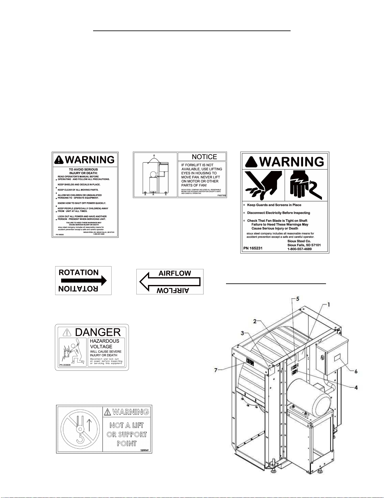
FOLLOW MACHINE SAFETY SIGNS & MESSAGES
Observe safe operating practices. Carefully read this manual and all safety signs on your equipment. Safety
signs must be kept in good condition. Replace missing or damaged safety decals or shields. Safety decals
and shields are available free of charge from Sioux Steel Company, 196 ½ E. 6
th
St., Sioux Falls, SD
57101-1265.
Learn how to use controls and operate equipment. Do not let anyone operate unit (especially youth) without
thorough training of basic operating and safety procedures.
Make no unauthorized modifications to equipment. Modifications may endanger function and/or safety of
unit. Periodically check all mechanical and electrical components. Keep unit in good working condition.
PRACTICE SAFE MAINTENANCE
Read and understand correct service procedures before operating. Keep area clean and dry to prevent
accidents. Machine should never be lubricated, serviced, or adjusted while it is in operation. Hands, feet
and clothing must be kept away from all moving parts. Keep all parts in good condition and properly
installed. Fix any damage immediately. Qualified service personnel should replace worn or broken parts.
Any built-up grease, oil, and debris around machine should be removed.
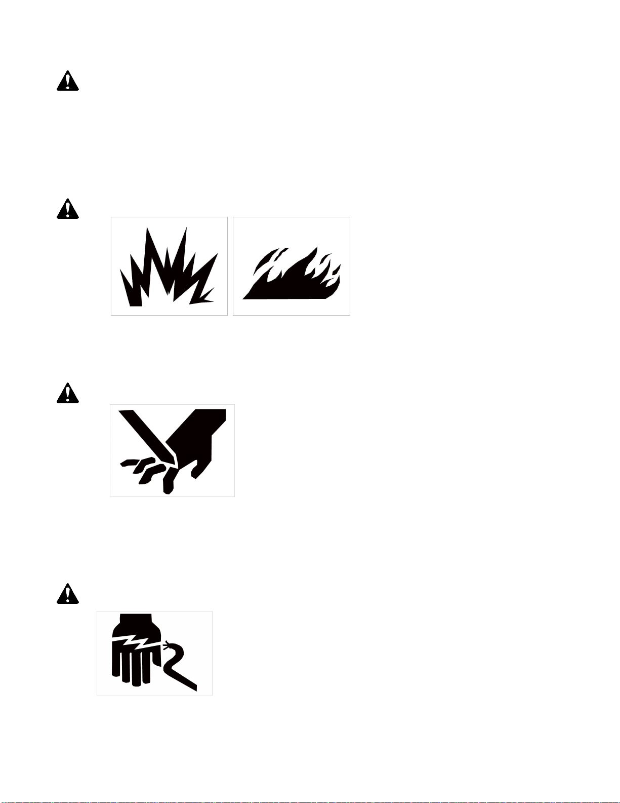
EMERGENCIES-KNOW WHAT TO DO
A first aid kit should be made readily available.
In the event of fire, a fire extinguisher should be at hand.
Have emergency numbers near your telephone for doctors, emergency medical squad, ambulance service,
hospital, and fire department and also have written directions to your location.
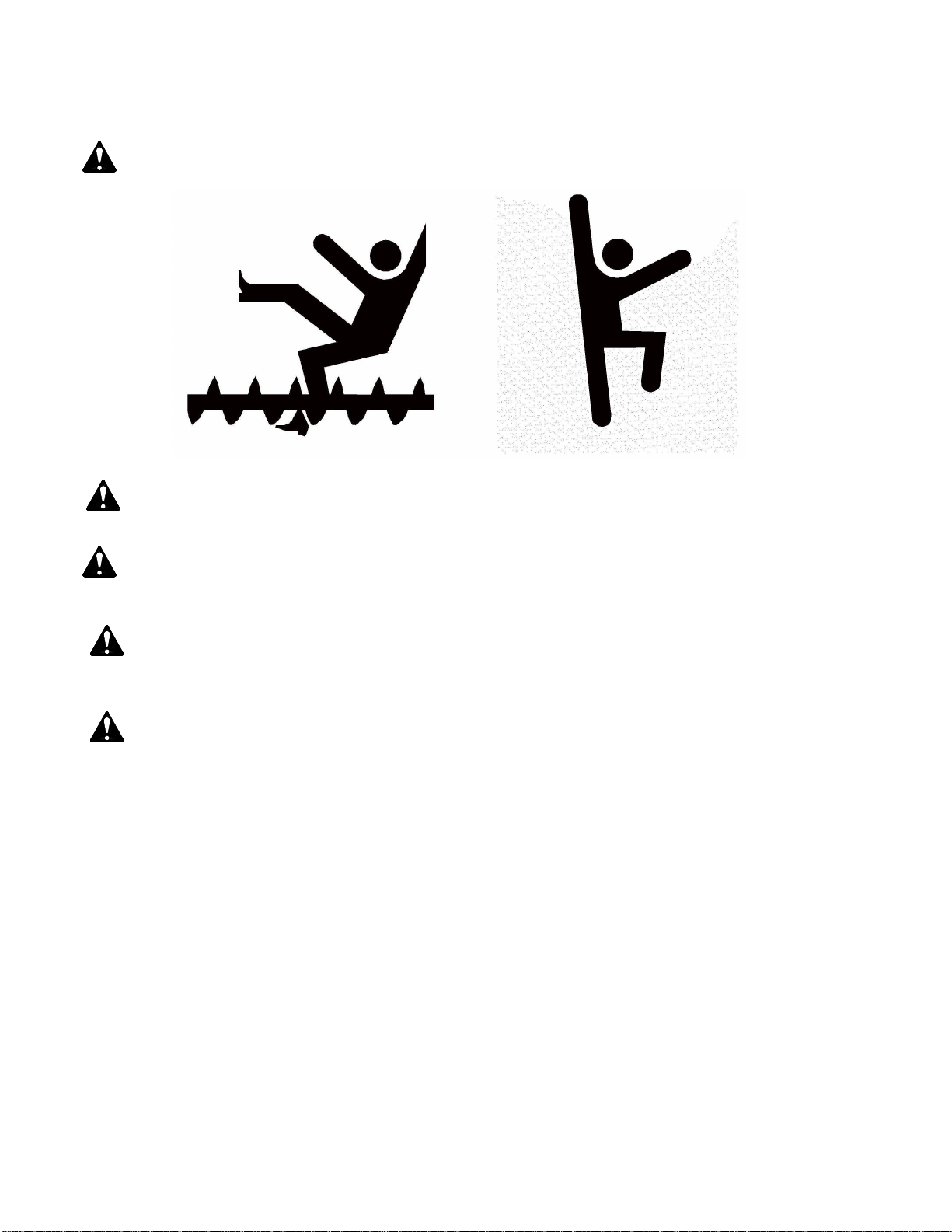
WEAR PROTECTIVE CLOTHING
CLOTHING- Avoid baggy clothes to avoid catching on moving parts.
HEARING PROTECTION- When high noise levels are encountered, ear plugs or muffs should be used.
EYE PROTECTION- Safety glasses should be worn at all times to protect eye from debris.
GLOVES- Always wear gloves to protect hands from sharp edges.
STEEL TOE SHOES- Appropriate shoes should be worn to protect toes from falling debris.
RESPIRATOR- In order to prevent breathing toxic fumes or dust, a respirator may be needed.
HARD HAT- Appropriate headwear should be worn to protect head from falling debris.
FALL PROTECTION- Appropriate fall protection should be worn when working at elevations greater
than six (6) feet.
Signal Word Color Potential Injury or Damage Likelihood of Occurrence
DANGER Red
Severe
Indicates an imminently hazardous situation which if not
avoided will result in death or serious injury.
WILL Occur
if Warning is ignored
WARNING Orange
Severe
Indicates a hazardous situation which if not avoided will
result in death or serious injury.
COULD Occur
if Warning is ignored
CAUTION Yellow
Minor
Indicates a hazardous situation which if not avoided will
result in minor or moderate injury.
WILL or COULD Occur
if Warning is ignored
NOTICE
Blue
or
Yellow
None
Indicates an important message or instruction not related
to personal injury.
N/A
SAFETY ALERT SIGNAL WORDS

6
WARNING: To reduce the risk of fire, electric shock, or injury to persons, observe the following:
1. Use this unit only in the manner intended by the manufacturer. If you have any questions, contact
the manufacturer.
2. Before servicing or cleaning unit, switch power off at service panel and lock the service
disconnecting means to prevent power from being switched on accidentally. When the service
disconnecting means cannot be locked, securely fasten a prominent warning device, such as a tag,
to the service panel.
3. Installation work and electrical wiring must be done by a qualified person(s) in accordance with
all applicable codes and standards, including fire-rated construction.
WARNING: To prevent explosion or fire:
1. Carefully review the operator’s manual.
2. Clean under floor, as fines may cause a bin fire.
3. Do not use to exhaust hazardous or explosive material and vapors.
4. Disconnect and lock out all power sources before servicing equipment.
WARNING: Keep clear of all moving parts
1. Keep people (ESPECIALLY YOUTH) away from equipment, particularly during operation.
2. Keep away from all moving parts. Entanglement can cause serious injury or death.
3. Keep inlet guard in place and in good working condition.
4. If fan is wired for suction, outlet must be shielded to protect an individual from moving parts.
Failure to follow the above precautions may cause serious injury or death.
CAUTION: To avoid electrocution, all equipment must be properly wired and grounded according to
electrical codes. Have unit wired by a qualified electrician.

7
Have your electrician install a main power disconnect switch capable of being locked only in the OFF
position. Mark disconnect clearly as to the equipment it operates. Always LOCK OFF main power
disconnect switch whenever equipment is not in use or when servicing the unit.
DANGER: Never enter bin, unless all power is locked off and another person is present. Rotating augers
can kill or dismember!
DANGER: Flowing grain may trap and suffocate. If you enter a bin of flowing grain you can be complete
submerged in grain in seconds. Failure to heed may cause serious injury or death.
WARNING: Heater must be electrically interlocked with fan. Never operate heater without airflow.
Failure to do so may cause serious injury or death.
CAUTION: To avoid personal injury, frequently inspect all mechanical and electrical components. LOCK
OFF all power whenever servicing equipment. Replace and/or repair worn parts. Be sure all
electrical wires are in good condition.
DANGER: Disconnect electricity before inspecting or servicing. Lock out all power and have another
person present. Always lock off all power and check with voltage meter before servicing.
Failure to do so may cause serious injury or death.

8
SAFETY DECAL LOCATIONS FOR CENTRIFUGAL FAN
Safety decals and shields are mounted whenever possible at the factory. Please check that all decals are in
place according to these drawings and in good legible condition. To order replacement decals or shields
(NO CHARGE) contact your dealer or Sioux Steel Company, 196 ½ E. 6
th
St., Sioux Falls, SD 57101-
1265. Please specify serial number.
IMPORTANT! The following safety decals should be mounted on your equipment as shown below.
(Note: When required, alternate languages are available upon request.) If suggested locations, are not
clearly visible, place safety decals in a more suitable area. Never cover up any existing safety decals.
Make sure the location for the decal is free from grease, oil, and dirt. Remove backing from the decal and
place in the proper position.
1. Warning – 165232 2. Caution – 187928 3. Warning – 165231 (Disconnect
(Safe Operation Decal) (Use Lifting Lugs) (Electricity/Keep Guards in Place)
4. Rotation – 165287 5. Airflow – 165288
(Apply as Shown) (Apply as Shown)
MOTOR SIDE DECAL LOCATION
6. Voltage – 203689
(Hazardous Voltage)
7. Warning – 208369
(Not a Lift or Support Point))

9
SAFETY DECAL LOCATIONS (Cont.)
8. Caution – 165234 9. Caution - 176716
(When Lifting) (Tighten Set Screws)
10. Serial Number- 203710
INLET SIDE DECAL LOCATION

10
PRE-INSTALLATION REQUIREMENTS
Foundation- Use the dimensions shown on the installation section of manual to determine appropriate size
of pad and location relationship to other equipment. Pad must be level for proper fan operation. Do not
anchor fan to pad, allow fan to “float” on pad. Pad for fan should be poured 2” lower than top of bin
foundation.
Transition- The transition duct should be of metal construction and allow for minimal resistance as it
transfers airflow from fan to the bin plenum. Obstructions at bin plenum entrance should be removed prior
to operating fan to avoid restricting airflow.
Roof Exhaust- There must be adequate exhaust ventilation to avoid excessive back pressure from building
in bin. Serious bin damage could result if this is not followed.
Power Supply- For reliable fan operation, adequate power must be supplied for your application. Your
power company should be contacted. They need to ensure that their system is sized properly for your
particular installation.
Wire Size- Voltage drop can occur when undersized wire is used. This will result in motor overheating and
shortened motor life. Refer to the chart in the electrical section for your particular application. Refer to the
nameplate on your motor for the full load current specifications.
Service Disconnect- Each fan motor must be supplied with an independent power circuit, equipped with a
fused disconnect switch. Locate this switch near the unit, as the power should be shut off before servicing
fan. It is the customer’s responsibility to provide a appropriate fused disconnect, over current, short circuit,
ground fault, and motor overload protection. These must be properly sized and connected to allow proper
motor operation. Failure to provide these components could cause severe motor damage and void the
manufacturer’s warranty.
UNLOADING / MOVING FAN
When unloading or moving fan with a fork lift, it is necessary to have forks fully engaged under fan and
then to chain or in some other way tie the fan back to the forklift to prevent the fan from tipping over
during transport and being damaged.
When using another method of unloading or moving fan, it is necessary to lift from the lifting eyes (which
are the 2 large holes located in the upper top of the housing closest to the motor). No other part on the fan
should ever be used for lifting or moving the fan.

11
INSTALLATION
1. Remove packaging material and inspect fan for any shipping damages. Report these at once to the
shipper.
2. Check all fasteners and electrical connections that may have loosened during shipment.
3. Rotate the fan wheel. Wheel must rotate freely and not contact the housing or inlet cone.
4. Install floor supports and unload for uniform airflow. The preferred arrangement is 180° between
fan and unload. Be sure floor is strong enough to support grain column. If two fans are installed on
bin, locate them about one bin sheet apart. Install single thermostat midway and use two-heater
relay kits.
5. Pour concrete fan pad as shown above using proper dimensions for your application. All
dimensions shown are for Sioux fans and transitions. (For Sioux transition information, see
transition assembly manual packed with transition.)
6. Install transition.
7. Set fan equipment on pad.
8. Caulk fan, heater, and transition flanges (as required for your application) with a material rated up
to 200° F.
9. Connect fan and heater together (if applicable). Make sure to center.
10. Connect fan (or assembly) to transition in like matter.
11. Secure all flanges with bolts provided.
12. Check that assembly is square with bin. Adjust leveling feet on fan until each supports equal
weight. Check that leg beneath motor mount is in firm contact with pad. Make sure to level fan.
13. Check all joints and seams for air gaps. Any leakage of air will reduce the efficiency of your fan.
5-20 HP SLAB OPTION
FAN SLAB REQUIEMENTS
DIMENSION CENTRIFUGAL FAN (HP)
5 7 ½, 10, 15 20
“A” W/HEATER NA 115” 122”
“A” W/O HEATER 91” 91” 98”
“B” W/HEATER NA 92” 98”
“B” W/O HEATER 66” 66” 74”
“C” 48” 48” 50”
“D” 41.75” 41.75” 49”
“E” 16” 16” 16”
“F” 32” 32” 34”
TRANSITION
BIN SIDEWALL
FAN
HEATER
A
B
F
C
E
D
BIN SIDEWALL
FAN
TRANSITION
CENTRIFUGAL FANS- POUR FAN
SLAB 2” LOWER THAN BIN SLAB
TO ALLOW FOR LEVELING SCREWS

12
INSTALLATION (cont.)
25-60 HP SLAB OPTION
Fan Slab Requirements
Dimension
Centrifugal Fan (HP)
25 30 40 50 60
A 74” 80” 80” 80” 82”
B 50” 68” 68” 68” 70”
C 16” 20” 20” 20” 20”
D 34” 48” 48” 48” 50”
It is very important that your fan is adequately supported!
If a concrete pad is not used, an angle iron frame may be constructed for the fan to rest on,
providing it is strong enough to support the fan’s weight. Two support cables should also be
used in conjunction with the angle iron frame, running from the top portion of the fan to the
adjacent bin wall stiffeners.
ALTERNATE CONSTRUCTION PLAN
CENTRIFUGAL FANS- POUR FAN
SLAB 2” LOWER THAN BIN SLAB
TO ALLOW FOR LEVELING SCREWS
CENTRIFUGAL FANS-
BUILD ANGLE FRAME 2”
LOWER THAN BIN SLAB
TO ALLOW FOR
LEVELING SCREWS
BIN SIDE
WALL
BIN SIDEWALL
BIN
FOUNDATION
FAN
TRANSITION
TRANSITION
BIN
SIDEWALL FAN
CABLES TO BIN
WALL STIFFENERS
A
B
C
D
APPROX.
70”- 25HP
77”- 30-50HP
78”- 60HP
ANGLE FRAME

13
INSTALLATION (cont.)
FAN CRADLE OPTION
Fan Cradle Kit Option (190323) (shown below) available for 5-25hp Centrifugal fans from Sioux Steel.
See separate manual 190349 for details.

14
IMPORTANT ELECTRICAL INSTALLATION INSTRUCTIONS!
DANGER: Always disconnect and lock out power before working on or around fan.
This unit should be installed by a qualified electrician in accordance with local, state, and federal electrical
codes. Violation of the electrical codes could affect the warranty of the unit.
NOTICE:
When connecting power to a unit, a UL/cUL Type 3R or better connector must be used at the entry point
into the electrical enclosure.
1. Verify that the incoming power supply has been deemed adequate by the local power company.
2. Verify that the wiring supplying power to the fan is sized correctly for the distance away from the
supply and fan horsepower. (See electrical diagram on page 16)
3. Verify that the safety disconnect is installed and sized correctly for the fan size.
4. Install a machine to earth ground for each individual fan. See next page.
5. Provide manual disconnect on or near bin in clear view from fan. Use properly sized time-delay
fuses or time-limit circuit breakers. Use properly sized safety ground wire.
6. The following wires must be supplied to each fan.
Fan Unit
Input Power
Less Controls
(Fan Only) With Controls
208-230vac 1ph L1 L2 G L1 L2 G
208-230vac 3ph L1 L2 L3 G L1 L2 L3 G
460vac 3ph L1 L2 L3 G L1 L2 L3 G
Note L1 and L2 legs for 2 8-23 vac 1ph
CAUTION!!!
On fan units provided with 1ph input power, main 208-230V power connections must be made to L1 and
L2.
Conduit Entries to a UL/cUL Type 3R enclosure should be made from the bottom of the enclosure using a
UL/cUL Type 3R rated conduit entry. Connect wires as shown (see electrical diagram on page 16).
NOTICE:
Thermal Overload Protection on Standard Fan Assemblies is set based on 230V application. If 208V
power is being used instead of 230V the thermal overload set point will need to be adjusted to prevent
nuisance tripping. Consult Factory for assistance.
(Cont. on next page)

15
MACHINE TO EARTH GROUND
It is very important that machine to earth ground rods be installed at the fan. This is true even if there is a
ground at the pole 15 feet away. This ground needs to be as close to the fan as possible, but no more than 8
feet away. The ground rods should be connected to the fan control panel according to the chart shown in
the electrical diagram (page 16) using the chart input ground column, or in accordance with local
requirements. The machine to earth ground provides additional safety if there is a short. It also provides the
grounding necessary for long life and operation of the solid state circuit boards used on control circuits and
the electronic ignition systems.
Proper Installation of the Ground Rod
(Ground rods and wires are not supplied). It is recommended that the rod not be driven into dry ground.
The following steps ensure proper rod installation:
1. Dig 2 holes large enough to hold 1 to 2 gallons of water far enough apart depending on the ground
resistance in your area.
2. Fill holes with water.
3. Insert 5/8” diameter x 8’ long bare copper rods through water and jab it into the ground.
4. Continue jabbing the rods up and down, the water will work its way down the holes, making it
possible to work the rods completely into the ground. This method of installing the rods gives a
good conductive bond with the surrounding soil.
5. Continue working rods down until top of rods are 1’ below the surface of the ground.
6. Connect the bare copper ground wires to the rods with the proper ground rod clamps.
7. Connect one bare ground wire to the ground lug on the starter found in the fan control box.
8. Connect the other green ground wire also to the ground lug located on the starter.
9. Ground wires must not have any breaks or splices. Insulated wire is not recommended for
grounding.

16
FINAL CHECK
•Check that all safety guards and screens are in place and not damaged. If parts are damaged
replace them.
•Check to make certain all decals are visible, legible, and not damaged. If decals are damaged,
replace them.
•Check control boxes to make sure they are completely closed and no wiring is exposed.
TEST RUN
When the fan is completely installed, the unit will need to be checked for proper rotation. Provide power to
the fan controls and start the fan momentarily. Fan wheel rotation should be in the same direction as
rotation decal indicates. If the decal is missing or damaged, note that wheel rotation should be as indicated
below. If wheel is rotating in the wrong direction, have a qualified electrician correct wiring.
Rotation
Direction
Of Wheel
Rotation
Decal

17
ELECTRICAL DIAGRAM
WARNING!
DISCONNECT ALL POWER TO STARTER PRIOR TO SERVICING
5HP to 10HP 230V 1PH Diagram
15HP 230V 1PH Diagram
MOTOR STARTER
SEE TABLE
FIELD CONNECTION
TERMINAL DETAIL
MOTOR “THERMALLY
PROTECTED”
SEE TABLE
AWG BLACK
SEE TABLE
AWG GREEN
SEE TABLE
T1
L2
M1
GND LUG
L1
L2
L
1
L2
L1
L1
M1
GND LUG
T2
L3
T3
2P C.B.
4AMP
L2
STARTSTOP
M1
13 14
M1
A1
A2
L1
L3
L2
230VAC
1PH 60Hz
CONNECTIONS TO BE
MADE IN
ACCORDANCE WITH
NEC STANDARDS
NC2
NC1
NO3
NO4
BRANCH CIRCUIT PROTECTION &
DISCONNECTING MEANS PROVIDED
BY ON-SITE ELECTRICIAN
C.B. SIZE (SEE TABLE)
(HIGH INRUSH MOTOR RATED)
UPSTREAM CIRCUIT
PROTECTION &
MAIN DISCONNECT
“M1”
STARTER
CONTACTOR
“M1”
STARTER
CONTACTOR
AWG BLACK
SEE TABLE
T1
T2
T3
PHASE “A”
PHASE “A”
PHASE “B”
FAN MAIN
DRIVE MOTO
R
PHASE “B”
SUPPLY GND
GND TO MOTOR
“L1” CNTR. TAP
“L2” CNTR. TAP
MOTOR STARTER/OVERLOAD
SEE TABLE
FIELD CONNECTION
TERMINAL DETAIL
MOTOR
SEE TABLE
AWG BLACK
SEE TABLE
AWG GREEN
SEE TABLE
T1
L2
M1
GND LUG
L1
L2
L
1
L2
L1
L1
M1
GND LUG
T2
L3
T3
2P C.B.
4AMP
L2
STARTSTOP
M1
13 14
M1
A1
A2
L1
L3
L2
230VAC
1PH 60Hz
CONNECTIONS TO BE
MADE IN
ACCORDANCE WITH
NEC STANDARDS
NC2
NC1
NO3
NO4
BRANCH CIRCUIT PROTECTION &
DISCONNECTING MEANS PROVIDED
BY ON-SITE ELECTRICIAN
C.B. SIZE (SEE TABLE)
(HIGH INRUSH MOTOR RATED)
UPSTREAM CIRCUIT
PROTECTION &
MAIN DISCONNECT
“M1”
STARTER
CONTACTOR
“M1”
STARTER
CONTACTOR
AWG BLACK
SEE TABLE
T1
T2
T3
PHASE “A”
PHASE “A”
PHASE “B”
FAN MAIN
DRIVE MOTOR
PHASE “B”
SUPPLY GND
GND TO MOTOR
“L1” CNTR. TAP
“L2” CNTR. TAP
OL

18
ELECTRICAL DIAGRAM (CONT.)
5HP to 50HP 230/460V 3PH Diagram
GENERAL NOTES:
1) Field wiring: Use Copper Conductors only, rated 75°C or greater. Wire gauge listed for power
connection is based on manufacture recommendation to maintain UL listing.
2) Replace all fuses with same or equivalent type, amperage & voltage ratings.
3) Lug or Terminal torque specifications:
a. 5-15 HP 230V 1ph
i. Line/Load: 35 lb-in
ii. Control: 7.0 lb-in
b. 5-10 HP 230/460V 3ph and 15 HP 460V 3ph
i. Line/Load: 15/15 lb-in
ii. Control: 7.0 lb-in
c. 15 HP 230V 3ph and 20-50 HP 230/460V 3ph
i. Line/Load: 35/75 lb-in
ii. Control: 7.0 lb-in
WIRE SIZE (Awg.) GROUND
WIRE (Awg.) BRANCH
CIRCUIT BREAKER
FLA
230v/460v
MOTOR
STARTER
AMP
230v/460v
OVERLOAD
SETPOINT
AMP
230v/460v
230v
3ph 460v
3ph 230v
1ph 230v 460v 230v 460v
5HP 12 14 12 14 20Amp 3P 15Amp 3P 12.8/6.4 9/9 15/7.3
5HP 8 10 50Amp 2P 30 65
7.5HP 10 14 10 14 30Amp 3P 15Amp 3P 18.6/9.3 25/12 25/12
7.5HP 8 10 50Amp 2P 36 65
10HP 10 12 10 12 30Amp 3P 20Amp 3P 25/12.5 32/18 31/16
10HP 6 8 65Amp 2P 48 65
15HP 8 10 10 10 50Amp 3P 30Amp 3P 37/18.5 50/25 41/24
15HP 4 8 80Amp 2P 58 80 70
20 6 10 8 10 65Amp 3P 30Amp 3P 50/25 65/40 60/30
25 4 8 8 10 80Amp 3P 50Amp 3P 58.5/29.3 80/40 65/32
30 3 8 6 10 100Amp 3P 50Amp 3P 70/35 95/40 93/39
40 6 10 65Amp 3P 46.3 50 51
50 4 8 80Amp 3P 58.5 65 65
MOTOR STARTER/OVERLOAD
SEE TABLE
FIELD CONNECTION
TERMINAL DETAIL
MOTOR
SEE TABLE
AWG BLACK
SEE TABLE
AWG GREEN
SEE TABLE
T1
L2
M1
GND LUG
L1
L2
L
1
L2
L1
L1
M1
GND LUG
T2
L3
T3
2P C.B.
4AMP
L2
STARTSTOP
M1
M1
A1
A2
L1
L3
L2
230/460VAC
3PH 60Hz
CONNECTIONS TO BE
MADE IN
ACCORDANCE WITH
NEC STANDARDS
NC2
NC1
NO3
NO4
BRANCH CIRCUIT PROTECTION &
DISCONNECTING MEANS PROVIDED
BY ON-SITE ELECTRICIAN
C.B. SIZE (SEE TABLE)
(HIGH INRUSH MOTOR RATED)
UPSTREAM CIRCUIT
PROTECTION &
MAIN DISCONNECT
“M1”
STARTER
CONTACTOR
“M1”
STARTER
CONTACTOR
AWG BLACK
SEE TABLE
T1
T2
T3
PHASE “A”
PHASE “A”
PHASE “B”
FAN MAIN
DRIVE MOTOR
PHASE “B”
SUPPLY GND
GND TO MOTOR
“L1” CNTR. TAP
“L2” CNTR. TAP
OL
L3
L3
OL
95
96
PHASE “C”
PHASE “C”
OL Set-Point
*OL is set from factory. If
Motor FLA differs from print
Adjust by turning set-point
screw

19
OPERATION
After initial installation and also prior to using the unit each season, check the operation to ensure proper
functioning, adjustment, and reliability.
FAN START-UP
1. Fan must be properly installed and connected as described in the installation section of this
manual. All seams and joints must be sealed.
2. With main power supply turned OFF, rotate the wheel by hand to make sure it turns freely without
contacting the housing or inlet cone.
3. Roof vents should be checked for blockage. If blockages are found, remove blockage. Open
manway door and top lid door for additional ventilation.
4. Turn ON main power disconnect switch. (All Guards and screens must first be secured in place.)
5. When pressing the START button:
A. Ensure wheel is rotating in proper direction per decal on housing. Electrician may- rewire
if direction is incorrect.
B. Ensure motor amperage is not exceeded by checking the current draw of the motor.
Maximum F.L. Amps listed on motor should never be exceeded.
FAN SHUT-DOWN
1. Press the fan STOP button on con control box (if equipped).
2. Shut off electrical power at main and at disconnect.
3. Close manway and top lid doors. Cover fan inlet to prevent harmful back-draft air currents from
passing through the grain and to avoid grain infestation from rodents and insects.
GRAIN QUALITY
Grain must be kept cool, dry, and insect free to prevent spoilage.
Notice: Please contact your local Cooperative Extension Services for area guidelines.
GRAIN STORAGE
Recommendations
Season Recommended Average
Grain Temperature
Grain Temperature to
Outside Temperature
Variance
Winter Above 35° F Within 10°-15° of
Monthly Temp. Avg.
Summer Below 65° F
Notice: For guidelines/methods/recommendations on specific grain type storage, please contact your
local Cooperative Extension Services.

20
MAINTENANCE
KEEP ALL GUARDS AND SCREENS IN PLACE.
DISCONNECT ALL POWER SOURCES
BEFORE DOING ANY REPAIR, MAINTENANCE OR INSPECTIONS!
BEGINNING OF EACH DRYING SEASON:
1. Remove inlet screen. Check for foreign material on fan wheel. With power locked off, turn fan by hand
to be sure it rotates freely.
2. Lubricate fan motor bearings with high temperature grease as indicated on motor nameplate or motor
fact sheet. Do not over grease. Check ventilation openings in motor for any blockage.
3. Check wiring of fan. Look for loose connections, bare wires, or rodent damage. Be sure to check
ignition wire and flame sensor wires for any damage.
AFTER DRYING SEASON:
The balance of a centrifugal blade is very critical. Vibration can cause the fan housing to crack. To prevent
this, check behind the blade for dirt, dust, or foreign material.
Cover fan inlet to keep out weather, pests, and to prevent “wind milling” which can cause wear on the start
switch in single phase motors.
DURING OFF SEASON:
Every six weeks, remove inlet cover and operate fan to redistribute grease in bearings. Let motor warm up
enough to force out any accumulated moisture.
Make sure control box cover is in place and secured. Turn off power.
ATTENTION: Sioux cannot warrant any roof damages due to excessive vacuum or internal pressure
caused by operating fans. Adequate ventilation should be provided for all powered air systems. Sioux does
not recommend the use of downward flow systems (suction). Severe roof structural damage can result from
any blockage of air passages.
To prevent structural damage to bin roof, roof vents and discharge louvers must be free of ice or other
obstructions before starting aeration fans. Operation of aeration fans during certain adverse weather
conditions can cause icing of roof vents and/or discharge louvers, which may result in roof failure.
Operating fan with bin empty may dislodge floor supports and cause floor to fail when bin is filled.
This manual suits for next models
20
Table of contents
Other Sioux Tools Fan manuals