SIRCHIE LTF100 Manual

TI04-394ENG-REV7
100 HUNTER PLACE, YOUNGSVILLE, NC 27596 USA
Ph: (919) 554-2244, (800) 356-7311 • Fax: (919) 554-2266, (800) 899-8181 • Web: www.sirchie.com • Email: [email protected]
1 of 8
Copyright© 2011 by SIRCHIE
All Rights Reserved.
SIRCHIE®
Products • Vehicles • Training
TECHNICAL INFORMATION
Laser Trajectory Finder Kit
Catalog No. LTF100
INTRODUCTION
Laser projection is the newest and most accurate method
used to determine projectile trajectories at crime scenes.
The laser is attached to a penetration rod, which is then
inserted into a bullet hole so that the laser beam can help
to determine the direction and angle from the source. It
may also be used to locate bullet exit points and other pos-
sible impact locations. The laser may be used with penetra-
tion rods and centering cones inserted into bullet holes, or
it may be used with the tripod mount to project its beam
through bullet holes.
The No. LTF100 Laser Trajectory Finder Kit includes a
high quality Laser Pointer, Centering Cones, Laser Con-
nectors, Universal Tripod Mount, Bullet Tips, Ballistic

TI04-394ENG-REV7
2 of 8
3 of 8
Angle Finder, Stringing Tips for attaching Colored Trajectory String, Multi-Colored Photographic Rods, and
Bullet Penetration Rods all contained in a handy carrying case.
EXPLANATION OF PRINCIPAL COMPONENTS
Ballistic Laser Pointer—This is a Class IIIa laser diode with an output of <5mW and operating at a fre-
quency of 630-680nm. Three L1154 batteries power the laser. It has a momentary ON/OFF switch with a
moveable collar, which, when moved into position, permits constant ON. The laser may be mounted on
the end of one of the Penetration Rods with a laser connector or it may be attached to the Universal Tri-
pod Mount for use with a photographic-type tripod.
Penetration Rods—Four aluminum Penetration Rods are supplied in the kit. These are inserted into bullet
holes to give a visual approximation of bullet trajectory. To facilitate entry into the bullet hole, one end of
the rod is machined with a bullet-like tip. To gain a more accurate gauge of trajectory, Centering Cones are
slipped onto the rod, one at the point of entry and one at the exit hole. These cones are then held in place
by O-Rings. The taper of the cones provides a snug t, thus providing more stable positioning of the rod.
Multi-Colored Photographic Rods—Six multi-colored rods are included to provide good photographic con-
trast at the crime scene. The Photographic Rods are attached to the Penetration Rods already positioned in
the bullet holes or may be used in place of Penetration Rods. The rods feature both male and female ends
to facilitate the connection of more than one rod.
Universal Tripod Mount—This device provides a means for mounting the laser to a photographic-type
tripod. Using this conguration, the laser beam may be directed into the bullet hole(s).
Ballistic Angle Finder—Using the Universal Tripod Mount, the Ballistic Angle Finder determines the angle
of trajectory from the vertical plane.
Stringing Tips and Colored Trajectory String—Once a Penetration Rod is positioned into the bullet hole,
a Stringing Tip may be attached to the rod. The Colored Trajectory String may then be attached to the
Stringing Tip.

2 of 8
TI04-394ENG-REV7
3 of 8
CAUTIONS/WARNINGS
• WARNING! Laser light may cause permanent eye damage. Do not look directly into the laser beam or
direct it toward others present at the scene.
• Do not look directly into the laser beam reection if it is directed toward a mirror or other highly reec-
tive surface.
• CAUTION! Do not connect more than two rods together as this added weight may damage the bullet hole.
OPERATION
Penetration Rods:
The Laser Trajectory Kit contains four Bullet Penetration Rods (aluminum-colored) that are used to mount
the Laser Pointer as well as the Multi-Colored Photographic Rods.
1. One end of each Penetration Rod is machined with a bullet-like tip to permit
easy insertion into bullet holes (Fig. 1).
2. Maneuver the bullet-tipped end of the rod into the bullet hole. Slip a Center-
ing Cone onto the rod and into the hole as deeply as it will go without undue
force. Slip an O-Ring onto the rod to hold the Centering Cone in place (Fig.
2).
3. If the projectile penetrated
the surface and the exit hole
is accessible, slip a Centering
Cone and O-Ring onto the
end of the rod as described
below (Fig. 3).
FIGURE 1
FIGURE 2—Illustration
O-RING
WALL
CENTERING CONE
PENETRATION ROD
FIGURE 3—Illustration
PENETRATION
ROD
O-RING O-RING
CENTERING
CONE
WALL

TI04-394ENG-REV7
4 of 8
5 of 8
Ballistic Laser Pointer:
The Ballistic Laser Pointer (Fig. 4) is equipped with a momentary ON/
OFF switch. To activate the beam, press the push button on the body
of the laser. For constant light, depress the button and slide the locking
collar over the switch. The Ballistic Laser Pointer may be used in two
different ways:
1. With a Photographic Rod or
Penetration Rod already in
place in a bullet hole(s), at-
tach a laser connector to the
Laser Pointer and screw it on
the other end of the rod (Fig.
5). To avoid cross-threading,
use extreme care when threading the rod into the laser as these are
extremely ne threads.
2. To use the laser to project a beam through a bullet hole, mount the
laser onto the Universal Tripod Mount using one of the Laser Con-
nectors. Attach the tripod mount onto a tripod using the pre-drilled
¼-20 mounting hole. Adjust the tripod’s height and lateral adjust-
ments until the laser beam penetrates through the bullet hole (Fig.
6).
LOCKING COLLAR
ON/OFF
FIGURE 4—Ballistic Laser Pointer
FIGURE 5
PENETRATION ROD
LASER CONNECTOR
FIGURE 6—(Tripod not included)

4 of 8
TI04-394ENG-REV7
5 of 8
Photography
Two methods are available to photograph the actual laser
beam:
Method 1: The camera should be set on a tripod and a slow
shutter speed should be used (i.e., 1/15 to 1/30 sec.). Us-
ing available light or indirect ash, introduce No. LTF100S
Photo Laser Smoke into the scene. This will make the laser
beam visible.
Method 2: Darken the room or area (Fig. 7). If outdoors, set
up for photos after dark. Set the camera on a tripod and lock
it into place. This technique is similar to painting with light.
Open the lens aperture fully and set the camera for Time
Exposure, or use the Bulb Setting, and use a locking cable
release. If only one bullet hole is in evidence, take a time
exposure of the laser beam for approximately 20* seconds. If multiple bullet holes are in evidence, cover
the camera lens with a heavy black cloth, set up the beam, and then lock the shutter open. After each time
that the laser is set up in a new bullet hole, uncover the lens for 20 seconds.
*NOTE: Use 20-seconds as a starting point. If using conventional lm, bracket exposures. If a digital cam-
era is used, the results will be apparent on the camera’s viewing screen.
FIGURE 7—Introduce Photo Laser Smoke
(LTF100S) into the scene to make laser beam
visible for photos.

TI04-394ENG-REV7
6 of 8
7 of 8
Photographic Rods:
Six Multi-Colored Photographic Rods are included to provide better contrast and easier recognition at the
crime scene.
1. Attach a Bullet Tip to one of the Multi-Colored
Photographic Rods. Insert it into a bullet hole using
the same technique described above for Penetration
Rods.
2. Photograph the scene using conventional techniques
(i.e., available light or ash).
3. String may also be attached to the rod end using a Stringing Tip (Fig. 8).
Ballistic Angle Finder:
The Ballistic Angle Finder is used to determine the angle of trajectory from the
vertical plane. It should be used with a standard tripod for best results. The
Ballistic Angle nder has a mount for the tripod and two laser pointers attached
to its base (Fig. 9).
Optional Forensic Rod Kit:
The FRK16 Optional Forensic Rod
Kit is available for use with the
LTF100 when a large number of
bullet holes are present at the crime
scene. It consists of 16 Multi-
Colored Acrylic Rods and 16 Centering Cones with a Forensic Rod Container for easy transport and storage
(Fig. 10).
FIGURE 8—Colored Trajectory String is attached to
a Photographic Rod using one of the Stringing Tips.
FIGURE 9—(Tripod not
included) FIGURE 10—FRK16 Components

6 of 8
TI04-394ENG-REV7
7 of 8
MAINTENANCE
Battery Replacement:
The Ballistic Laser Pointer requires three (3) Type L1154 batteries (included).
1. Unscrew the cap of the battery compartment located on the rear of the laser. Remove the old batteries.
2. Install three new L1154 batteries with the + terminal facing out of the battery compartment as shown in
Fig. 11 Illustration.
3. Replace the battery compartment cover.
4. Test the laser by depressing the ON/OFF button. Remember, DO NOT look directly into the laser beam.
FIGURE 11—Illustration
– + – + – +

TI04-394ENG-REV7
8 of 8
LTF100 KIT CONTENTS:
1- LTF101 Ballistic Angle Finder
1- LTF102 Ballistic Laser Pointer Class IIIa
w/batteries (type L1154)
1- LTF103 Bullet Penetration Rods, set of 4
1- LTF104 Multi-Colored Photographic Rods,
set of 6
2 – LTF105 Laser Connectors
1- LTF106 Bullet Tips, set of 2
1- LTF107 Stringing Tips, set of 2
1- LTF108 Centering Cones,
set of 4
1- LTF109 O-Rings, set of 4
1- LTF110 Universal Tripod
Mount w/mounting
screws
1- LTF111 Roll of Colored
Trajectory String, 250 ft.
1- LTF100C High-Impact
Carrying Case w/
Custom Foam Insert
OPTIONAL FRK16 KIT CONTENTS:
16- FRK001 Multi-Colored Acrylic Rods
16- FRK002 Centering Cones
1- FRK16C Forensic Rod Container
No. LTF100S
CAT. NO. ACCESSORY ITEMS DESCRIPTIONS
LTF100S Optional Photo Laser Smoke (aerosol
can), 8 oz. (236ml)
BM6009 Optional Heavy-Duty Tripod
LFT112RS Optional 22 Caliber Rod Set, 4 each
LFT113 Optional Reflective Yarn, 275 ft. (84m)
LFT102 Extra Laser Pointer w/locking collar
FRK16 Optional Forensic Rod Kit
Table of contents
Other SIRCHIE Tools manuals
Popular Tools manuals by other brands
Clarke
Clarke CHT 455 quick start guide
Magswitch
Magswitch 400 Operation and instruction manual
Piper Aircraft Corporation
Piper Aircraft Corporation Arrow IV PA-28RT-201 Information manual
Pattfield Ergo Tools
Pattfield Ergo Tools PE-500PF Original instructions

Matco Tools
Matco Tools MT1811 operating instructions
Ratio
Ratio ML400M Original instructions

Graco
Graco 17R720 Installation-Parts
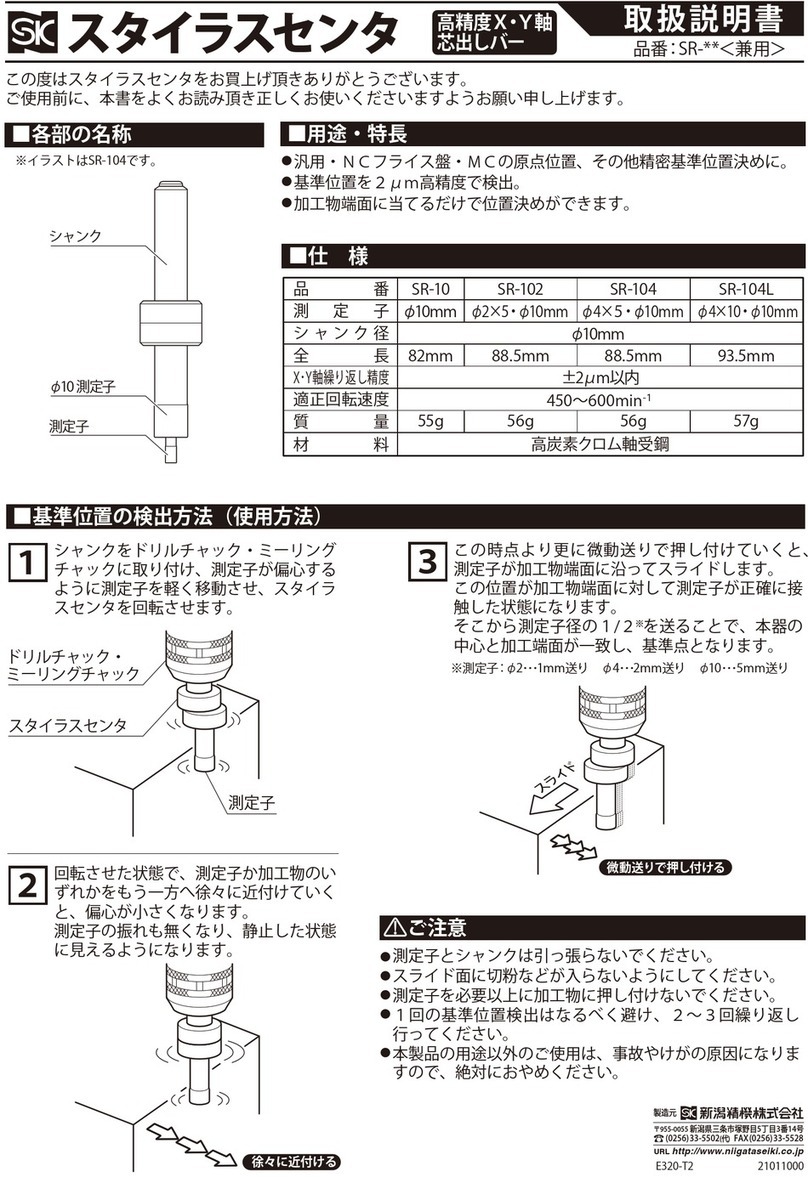
Niigata seiki
Niigata seiki SR-104 instruction manual

SGS
SGS GPA520 owner's manual

Max
Max Rebartier RB398S Instruction manual and safety instructions
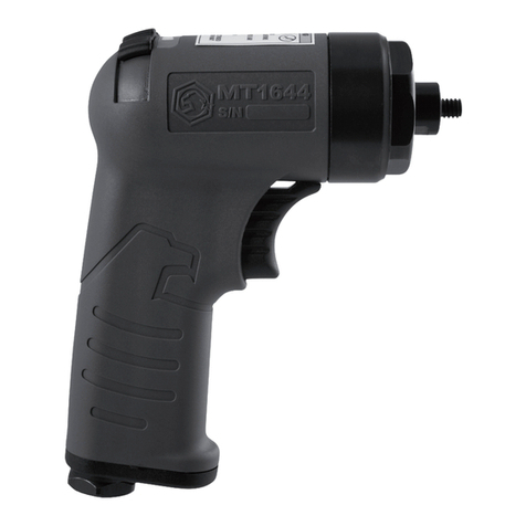
Matco Tools
Matco Tools MT1644 Operating instructions, warning information, parts breakdown
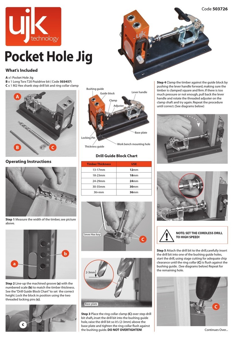
ujk technology
ujk technology Pocket Hole Jig operating instructions
