SIRE XROOM Specification sheet

OPERATING AND INSTALLATION MANUAL
RECOVERY AND HEATING UNIT
XROOM
1
Version 1 – GBR(23/06/2021) D-502-0152

TABLE OF CONTENTS
1. General information .................................................................................................................................................................. 5
1.1. Introduction........................................................................................................................................................ 5
1.2. Warnings and Symbols ........................................................................................................................................................................... 5
1.3.1. Unit Designation ..................................................................................................................................................................................... 6
1.3.2. Prohibited environment, use, installation of Xroom: ............................................................................................................................ 6
1.4. Transport, Delivery Control, and Storage ..............................................................................................................7
1.4.1. Transport ................................................................................................................................................................................................ 7
2
Version 1 – GBR(23/06/2021) D-502-0152
1.4.2.
1.4.3.
Delivery Inspection................................................................................................................................................................................. 7
Storage.................................................................................................................................................................................................... 7
1.5. Contents of the Package ......................................................................................................................................7
1.5.1. Xroom 100 (XR1-010-EC…)...................................................................................................................................................................... 7
1.5.2. Xroom 250 (XR1-025-EC…)...................................................................................................................................................................... 8
1.6. Before Commencing the Installation ............................................................................................................................... 8
2. Technical Parameters................................................................................................................................................................. 9
2.1.
2.1.1.
Design of the Xroom unit.................................................................................................................................................. 9
Front metal cover (position 1) .............................................................................................................................................................. 11
2.1.2. Installation template (position 2) .........................................................................................................................................................11
2.1.3.
2.1.4.
2.1.5.
2.1.6.
2.1.7.
2.1.8.
Mounting pins (position 3) ................................................................................................................................................................... 11
Unit body –fitting (position 4) ............................................................................................................................................................. 11
Unit cover (position 5) .......................................................................................................................................................................... 11
Reinforcement (position 6) ...................................................................................................................................................................11
Bolt M6x30 (position 7) ........................................................................................................................................................................ 11
Filters (position 8) ................................................................................................................................................................................. 12
2.1.9. Filter caps (position 9)........................................................................................................................................................................... 12
2.1.10. Preheating (position 10) ....................................................................................................................................................................... 12
2.1.11. Fans (position 11).................................................................................................................................................................................. 12
2.1.12.
2.1.13.
2.1.14.
2.1.15.
2.1.16.
2.1.17.
2.1.18.
Recuperator (position 12) ..................................................................................................................................................................... 12
Electric heat exchanger (position 13) ................................................................................................................................................... 12
Controller (position 14)......................................................................................................................................................................... 12
Regulator box (position 15) .................................................................................................................................................................. 12
FILTER RESET button (position 16)........................................................................................................................................................ 12
Limit switch (position 17)...................................................................................................................................................................... 12
Main switch (position 18) ..................................................................................................................................................................... 12
2.1.19. Supply cable (position 19)..................................................................................................................................................................... 12
2.1.20. Water exchanger (position 20) ............................................................................................................................................................. 12
2.1.21.
2.1.22.
Bleed valve (position 21) ...................................................................................................................................................................... 12
Flexible hoses for connection to the heating system (position 22) ..................................................................................................... 12
2.2. Main dimensions of the Xroom unit ...................................................................................................................13
2.2.1. Xroom-100 (XR1-010-EC...) .................................................................................................................................................................. 13
2.2.2. Xroom-250 (XR1-025-EC…).................................................................................................................................................................... 13
2.3. Technical parameters of Xroom units ............................................................................................................................ 14
2.3.1.
2.3.2.
Basic technical parameters ........................................................................................................................................ 14
Acoustic Data........................................................................................................................................................................................ 15

2.3.3.
3
Version 1 – GBR(23/06/2021) D-502-0152
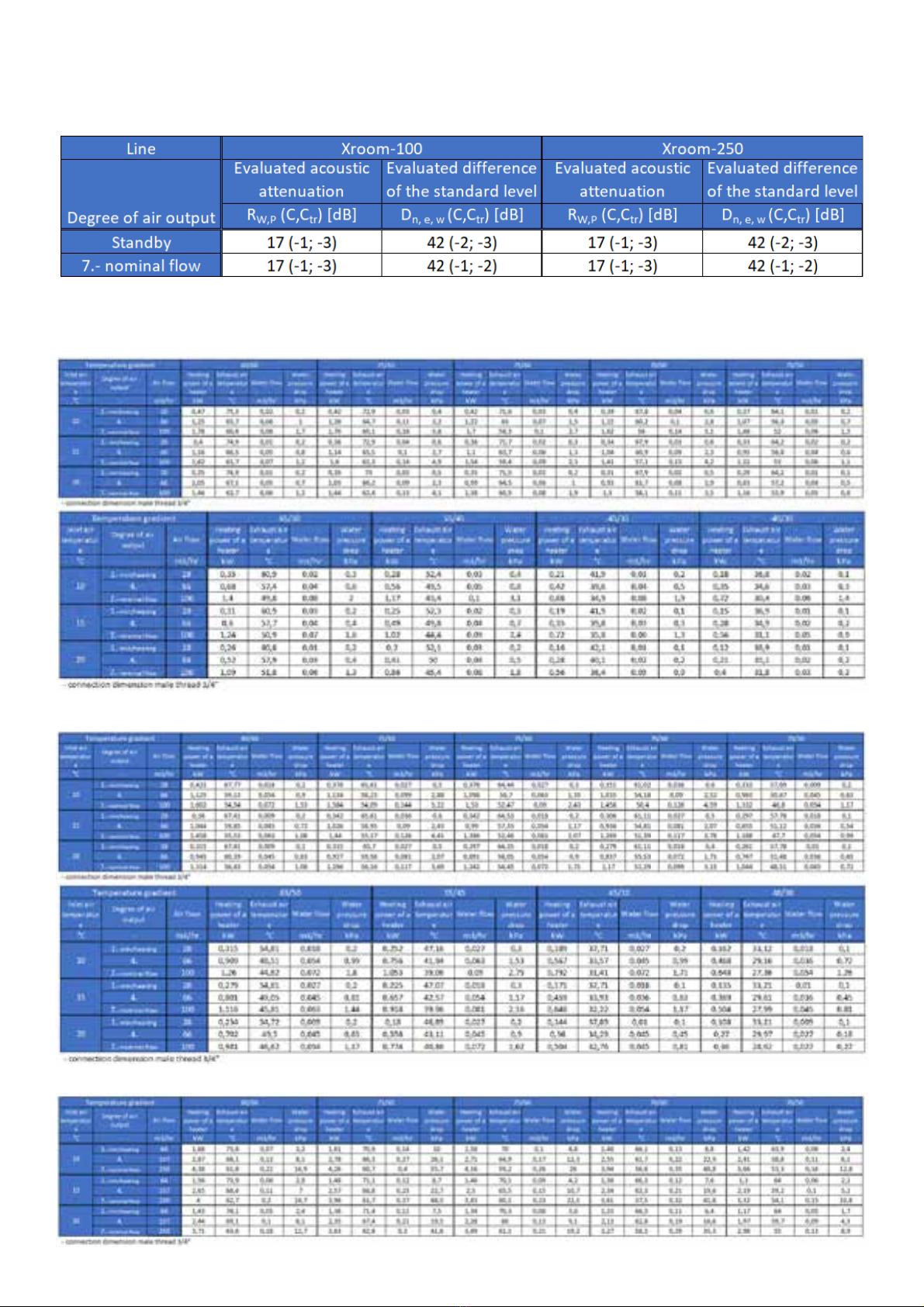
Technical data of water heaters........................................................................................................................................................... 16
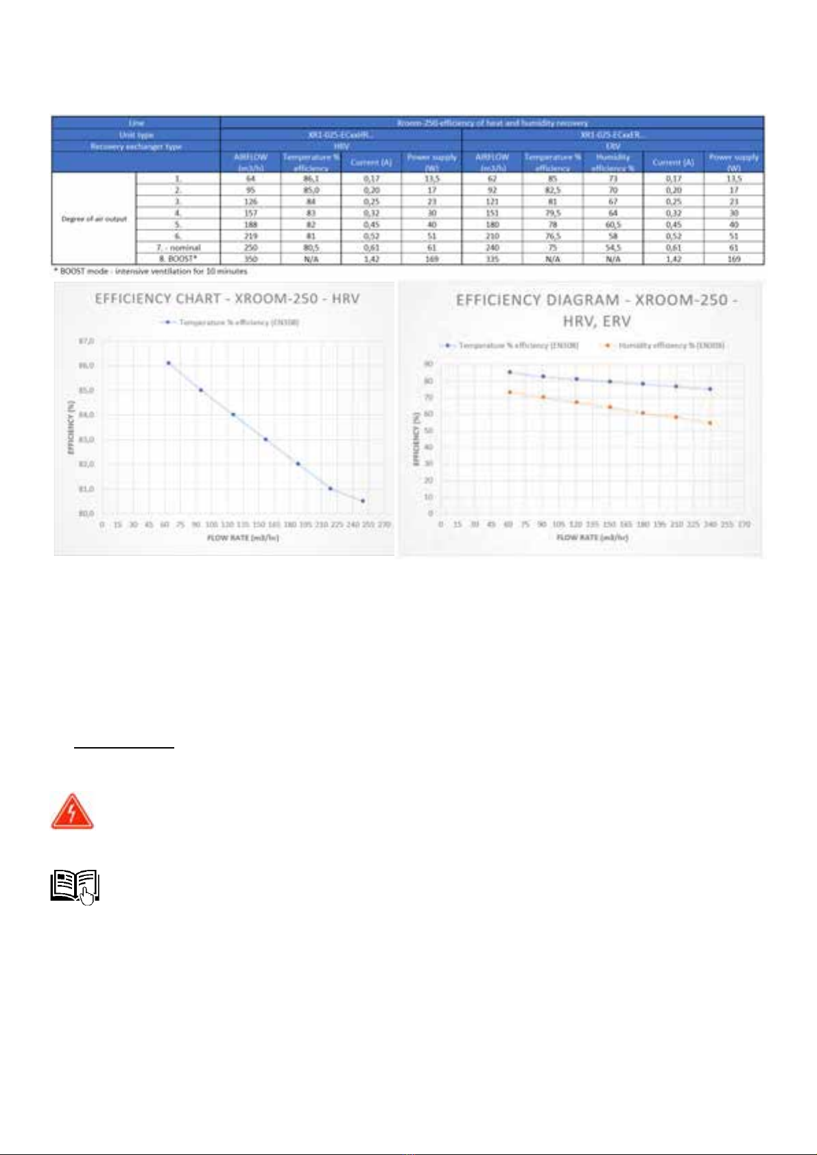
2.3.4. Heat and moisture recovery efficiency ................................................................................................................................................ 17
3. Unit Installation ....................................................................................................................................................................... 18
3.1.
3.1.1.
3.1.2.
General information, recommendations, and safety when installing the Xroom units............................................... 18
Electrical safety before installation of the unit.................................................................................................................................... 18
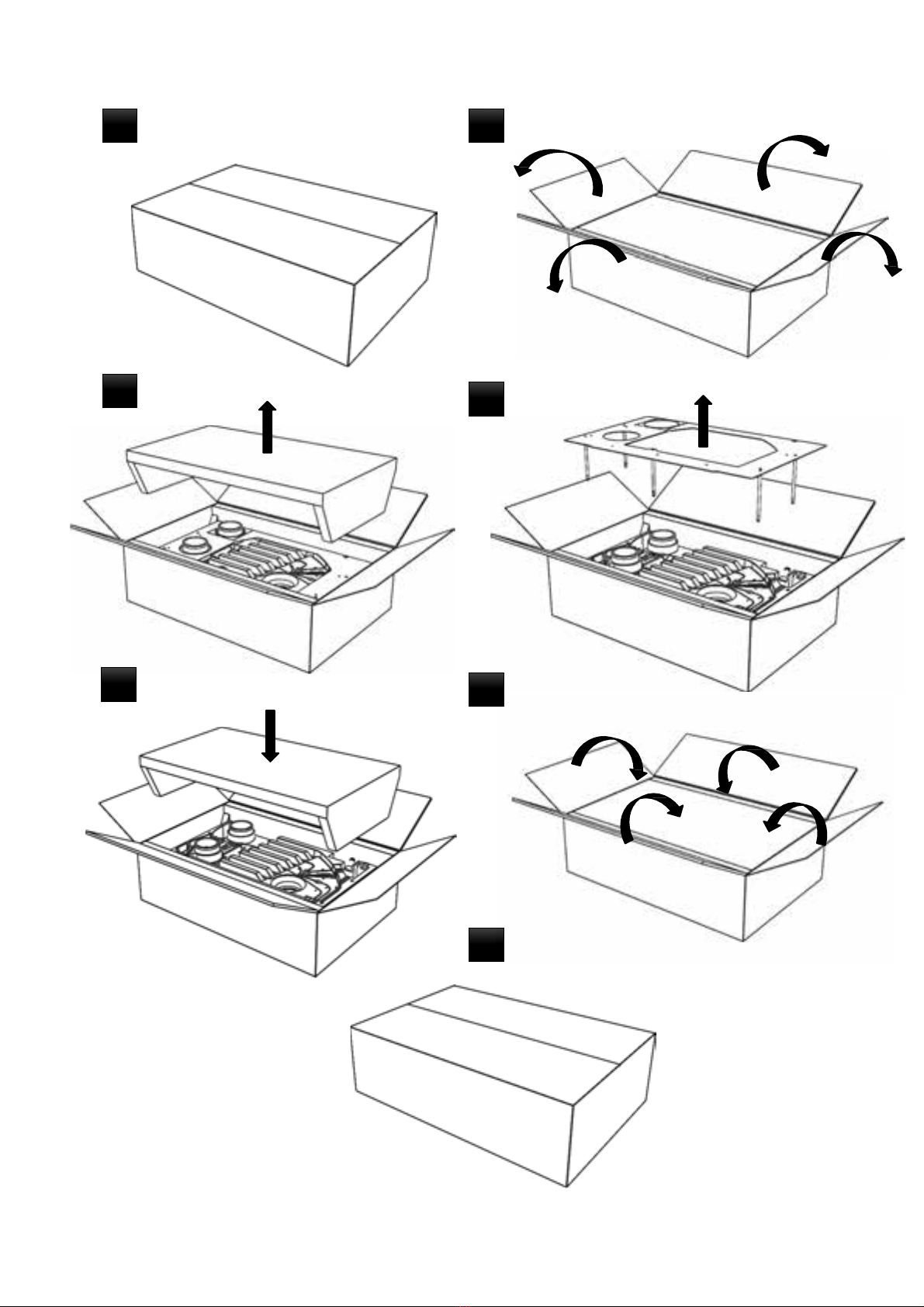
Unpacking ............................................................................................................................................................................................. 18
3.1.2.1.
3.1.2.2.
3.1.3.
Unpacking the Xroom Unit –Box 1 ...................................................................................................................................................... 18
Unpacking Installation –Box 2 ............................................................................................................................................................. 20
Unit Location ........................................................................................................................................................................................ 21
3.1.3.1. Location During the Building Reconstruction ...................................................................................................................................... 21
3.1.3.2.
3.1.3.3.
3.1.4.
3.1.5.
Location and operation of the unit in the area with a furnace (fire place) ......................................................................................... 21
Unit Location and Operation in the Area with an Air Conditioning Unit ............................................................................................ 21
Minimum Installation Distances .......................................................................................................................................................... 21
Installation Positions of the Xroom Unit.............................................................................................................................................. 22
3.2. Xroom Unit Installation ..................................................................................................................................... 22
3.2.1. Installation Components Required for Installation of the Xroom Unit ............................................................................................... 22
3.2.2. Fitting and Mounting the Installation Template with Mounting Pins................................................................................................. 23
3.2.2.1.
3.2.2.2.
Fitting the installation template on the wall when using the construction module........................................................................... 23
Fitting the Installation Template on the Existing Wall ........................................................................................................................ 23
3.2.2.3. Installation Template Mounting .......................................................................................................................................................... 23
3.2.3. Preparation of Piping Holes in the Existing Wall.................................................................................................................................. 24
3.2.4. Preparation of Supply and Drain Piping ...............................................................................................................................................25
3.2.4.1. Extension of piping for walls with a thickness greater than 500 mm.................................................................................................. 26
3.2.4.1.1. Extension of the Supply Piping with a Damper Assembly ................................................................................................................... 26
3.2.4.1.2. Drain piping extension –white plastic tubes....................................................................................................................................... 26
3.2.5. Installation of the Supply and Drainage Piping on the unit................................................................................................................. 27
3.2.6. Gluing Insulating Pads .......................................................................................................................................................................... 28
3.2.7. Installation of the Xroom unit on the wall........................................................................................................................................... 29
3.2.8. Xroom Unit Final Fitting ....................................................................................................................................................................... 29
3.2.8.1. Electric heater variant (XR1-010-ECE1...), without heating –cold (XR1-010-ECS0...) ......................................................................... 29
3.2.8.2. Water heater variant (XR1-xxx-ECV1...)............................................................................................................................................... 30
3.2.9. Securing, Insulating Piping in the Wall................................................................................................................................................. 31
3.2.10.
3.2.11.
Fitting the Piping on the Outer Side of the Wall with Outlet .............................................................................................................. 32
Installation of the Front Metal Cover................................................................................................................................................... 32
3.3. Electrical Installation –Connection to Mains ...................................................................................................... 33
3.3.1. General Information –Safety ............................................................................................................................................................... 33
3.3.2. Connection to Mains ............................................................................................................................................................................ 33
3.3.2.1.
3.3.2.2.
3.3.2.3.
3.3.3.
Connection of the Unit to the Wiring Box............................................................................................................................................ 34
Connecting the Unit to the Electrical Outlet ........................................................................................................................................ 34
Recommended Xroom Unit Protection................................................................................................................................................ 34
Display of electrical parameters........................................................................................................................................................... 34
4. Regulation ................................................................................................................................................................................ 35
4.1.
4.2.
4.2.1.
General Information –Safety ......................................................................................................................................... 35
Electrical Accessories to the Xroom Unit ....................................................................................................................... 35
Connecting Electrical Accessories ..............................................................................................................................35

4.2.2.
4
Version 1 – GBR(23/06/2021) D-502-0152
Radon Sensor Connection –AQS RADON ......................................................................................................................................................... 36
4.2.2.1.
4.2.2.2.
Technical Parameters of the Sensor for Connection to the Unit...................................................................................................................... 36
Functionality of the unit after connecting the radon sensor ........................................................................................................................... 36
4.2.3. External Contact Connection –EXT 1................................................................................................................................................................ 36
4.2.3.1. Technical Parameters of External Contact........................................................................................................................................................ 37
4.2.3.2.
4.3.
Functionality of the Unit when Controlled by External Contact EXT1 ............................................................................................................. 37
Wiring Block Diagram ....................................................................................................................................................................................... 37
5. Commissioning ......................................................................................................................................................................... 38
5.1.
5.2.
5.3.
5.3.1.
Prior to first startup, check:............................................................................................................................................38
Activation –Basic UnitCommissioning .......................................................................................................................... 38
Controller Operating Modes .......................................................................................................................................... 38
Sleep Mode –Regular Operating Mode ........................................................................................................................................................... 38
5.3.2.
5.3.3.
Control Mode –1 click ...................................................................................................................................................................................... 39
Unit Setting Mode –2 clicks.............................................................................................................................................................................. 39
5.4. Unit Control ......................................................................................................................................................39
5.4.1. Control panel –controllers ............................................................................................................................................................................... 39
5.4.2.
5.4.3.
5.4.4.
Description of the functions of the buttons and regulation........................................................................................................................... 40
Description of the ventilation power setting range ......................................................................................................................................... 41
Ventilation Power Settings ............................................................................................................................................................................... 41
5.4.5. Temperature Setting Range –only in the electric version (XR1-xxx-ECE1...).................................................................................................. 41
5.4.6.
5.4.7.
5.4.8.
Setting the Required Temperature:.................................................................................................................................................................. 41
Display of the Indicated Statuses on the Controller by LEDs ........................................................................................................................... 41
Hidden Regulation Functions............................................................................................................................................................................ 42
5.4.9. Automatic Unit Control using AQS Sensors...................................................................................................................................................... 42
6. Replacing Filters ....................................................................................................................................................................... 43
6.1.
6.2.
6.3.
Removal of a filter .......................................................................................................................................................... 43
Filter Inserting ................................................................................................................................................................. 44
Reset filter countdown ................................................................................................................................................... 44
7. Regular Maintenance and Cleaning of Xroom Units............................................................................................................... 45
7.1.
7.1.1.
7.1.2.
Visual Inspection of the Unit Casing ................................................................................................................................................................. 45
Visual Inspection and Cleaning of the Heat Exchanger .................................................................................................................................... 45
Visual Inspection of the Supply Cable .............................................................................................................................................................. 46
7.2. Inspection –cleaning of the inner area of the unit –disassembly......................................................................... 46
7.2.1. Cleaning the Fan Chamber and Fans................................................................................................................................................................. 46
7.2.2. Visual Inspection –Cleaning of Preheating, if fitted with the unit (XR1-xxx-ECxxxxP...)................................................................................... 47
7.2.3. Visual Inspection –Cleaning of Inlet and Drainage Piping ............................................................................................................................... 47
7.2.4. Visual Inspection and Cleaning of the Heat Recovery Exchanger .................................................................................................................... 48
7.2.5. Re-installation of Internal Components into the Unit...................................................................................................................................... 48
8. Servicing ................................................................................................................................................................................... 49
8.1.
8.2.
Error Messages –Troubleshooting Procedure............................................................................................................... 49
Failure persists ................................................................................................................................................................ 50
9. Final Decommissioning, Dismantling, and Disposal................................................................................................................ 50
10. Warranty ............................................................................................................................................................................. 50
11. In Conclusion ....................................................................................................................................................................... 51

pac
1. General information
1. Introduction
-This document “Operating and Installation Manual” is intended for decentralised Xroom recovery units
(hereinafter referred to as the “Unit”) with apossible combination of water or electrical heating –2in1.
At the same time, it is superior to the brief manual placed directly on the unit, the so-called “Quick
Manual”.
-Installation and connection of the unit may only be performed by atrained person with the appropriate
authorisation for the connection of electrical equipment who has the appropriate tools and resources
at his disposal.All the instructions and recommendations provided in this manual must be observed
during installation.
-Detailed familiarisation with this document is important for the unit's correct and safe installation and
functioning. Failure to comply with the conditions set out in this document may lead to the unit's
malfunction.
-Please, retain this unit installation manual for future reference after reading it thoroughly.
-It is forbidden to interfere in any way with the unit's internal connection other than as specified in this
manual. Due to the continuous development of our products, we reserve the right to change this manual
without prior notice.
-Children and persons with reduced physical, sensory, or mental capabilities, or lack of experience and
knowledge, may use the unit only under supervision or if they were instructed on the unit's use in asafe
way and understand potential risks.
1. Warnings and Symbols
-The following names and symbols shall be used in the operating manual, on the packaging, and on the
product for particularly important information:
Warning, pay attention to all the risk alerts and warnings, as well as preventive measure instructions.
Danger, observe all the warnings; there is a risk of electric shock or a situation, which can result in death
or serious injury, if not prevented.
Reference to other manual sections
Read the operating manual.
Protective conductor connection
Notification of the correct position when handling and storing the packaging.
Notification of the need for protection against moisture.The product –packaging marked with this
symbol must not be transported on open vehicles and stored in roofless buildings and on the ground
without apad.
Notification of the content –product’s fragility and the need for careful handling of the packaged
product.
Notification of the need for protection against moisture and of the fragility of the product inside the
kaging.
5
Version 1 – GBR(23/06/2021) D-502-0152

Caution –never cover the unit.This symbol on the unit indicates that any material covering the unit can
cause afire.
Caution very hot surface.
Caution -portions of this product may become hot and cause burns.Pay particular attention to the presence of
children and vulnerable people.
3. Use of the Xroom unit
1. Unit Designation
- The Xroom is an air-conditioning unit using ventilation technology with recovery of heat (countercurrent
recovery exchanger) and humidity (enthalpy exchanger) with the possibility of independent space heating
at the unit’s installation site (depending on the selected unit type).By default, the unit is equipped with
aCO2air quality sensor (alternatively also with an RH humidity sensor), which allows it to ventilate only
when needed.The user shall set only the unit's output (flow rate, temperature –based on the selected
type) according to the place of use (how many people will be in the room) and the unit will ventilate and
heat as per the actual needs.
-The unit can be used in spaces with the maximum nominal flow requirement:
o100 m3/h – Xroom 100 –regular residential premises, smaller offices, hotel rooms, etc.
o250 m3/h – Xroom 250 –larger office facilities, school classrooms, hospital rooms, etc.
-The unit is designed for horizontal installation on the perimeter wall, which provides simple access to the
outside environment (fresh air).
-You can install the unit in the wall with the minimum thickness of 180 mm.
-The unit is intended for continuous operation with the possibility of using the manual operation mode
(ventilates continuously) or the automatic operation mode (ventilates as needed –required by the air
quality sensors –AQS).
-The unit can be used not only for controlled ventilation, but also for space with heating requirements
(ventilation and heating are independent of each other). In case of type configuration with:
oElectric heating, theunit is equipped with advanced regulation with temperature sensor for the
given area (installation site).Using an integrated temperature sensor, the user can choose the
appropriate temperature degree that meets his requirements,
oWater heating, the unit is equipped with awater exchanger, which is connected to the standard
heating system using an external G 3/4" thread and is controlled using an independent fitting –
thermostatic valve and head (not included in the supply).The unit control is equipped with a
temperature sensor that detects hot water in the exchanger and starts the heating function.The
function of the water heater depends on the function of the boiler –heating system.
-The unit also allows for the antifreeze temperature function (tempering the heated space to prevent
freezing).In the electric version, settings are on the controller, and in the water version, they are on the
thermal head (snowflake symbol).
-The unitis intended for indoor covered and dry areas with aroom temperature of +5 °C to +30 °C and the
maximum relative humidity of 70%, non-condensing.
-The temperature of supplied fresh air from the outside may be between -20 °C and +40 °C (applies to
the version with preheating).If the temperature of the supplied air is lower than -20 °C, the unit may
be switched off automatically in order to protect it from possible damage.
1.3.2. Prohibited environment, use, installation of Xroom:
-Exhausting burning or glowing substances!
-Exhausting readily flammable or explosive gases,
-Exhausting aggressive media,
-Exhausting liquids of any kind,
-In an environment with an increased incidence or risk of explosion, flammable substances, and
increased dust and/or air containing other harmful impurities,
6
Version 1 – GBR(23/06/2021) D-502-0152

-In an environment with higher condensation humidity, such as: bathrooms, swimming pools, saunas,
etc.,
-The unit must not be installed just below the electrical socket or wiring box,
-The unit must not be installed in aposition that could affect its proper functioning, or near the curtains
or other flammable materials.
-Neither the manufacturer nor the supplier is liable for damage caused by improper use of the units. The
user bears the risk.
4. Transport, Delivery Control, and Storage
1. Transport
-During transport, keep the product in the position indicated by the symbol on the packaging.
-The packaging must not be loaded with a weight higher than that permitted by the manufacturer.
-The packaging must not be exposed to ambient effects.
-The transport air temperature must range between -25 to 55 °C,
-The transport relative humidity must range between 10 % and 90 %non-condensing.
-Use adequate tools to prevent damage to the goods and damage to the health and safety of persons.
-In the case of further transport without original packaging or with changed original packaging, it must be
ensured that the equipment is optimally secured and protected against damage.
1.4.2. Delivery Inspection
-Before starting the installation and before unpacking the unit from the box, it is necessary to check for
any traces of damage on the packaging.If the packaging is damaged, write arecord of the damage and
contact your carrier, please.
-Check if you have received the product actually ordered by you.After unpacking, check that the unit and
other components are in order.Please, report any discrepancy with the order to the supplier
immediately.
If an order complaint is not made immediately after delivery, it will not be considered later.
1.4.3. Storage
-If you do not plan to install the unit immediately after purchase, it must be stored in an indoor, non-
condensing environment at temperatures ranging between +5 to +40 °C. If the product is transported at
temperatures below 0 °C, it must be put into the working environment where it will be installed for at
least 2hours after unpacking.
1.5. Contents of the Package
1.5.1. Xroom 100 (XR1-010-EC…)
Box 1 – Xroom unit
7
Version 1 – GBR(23/06/2021) D-502-0152
-Xroom unit body with front metal cover
-installation template with assembly pins
1pc
1pc
-bolt M6x25 5pc
-bolt M6x20 with a plastic head 2pc
-Quick manual + safety data sheet 1pc
-serial plate 1pc
Box 2 –mandatory installation accessories XR1-01-DUCT-1 (for installation into a wall with thickness of the
max. 500 mm)
-plastic white tube Ø125 mm, length 500 mm 1pc
-supply line assembly with damper Ø125 mm, length 500 mm 1pc
-plastic square outlet with damper 1pc
-plastic square outlet without damper 1pc
-self-tapping bolt Ø4x22 4pc
-insulation washer 170x170x5 with hole Ø127 mm 2pc

1.5.2. Xroom 250 (XR1-025-EC…)
Box 1 –Xroom unit
-Xroom unit body with front metal cover
-installation template with mounting pins
1pc
1pc
-bolt M6x25 5pc
-bolt M6x20 with a plastic head 3pc
-Quick manual + safety data sheet 1pc
-serial plate 1pc
Box 2 –mandatory installation accessories XR1-025-DUCT-1 (for installation into a wall with thickness of the
max. 500 mm)
-plastic white tube Ø150 mm, length 500 mm 1pc
-supply line assembly with damper Ø150 mm, length 500 mm 1pc
-plastic square outlet with damper 1pc
-plastic square outlet without damper 1pc
-Self tapping bolt Ø4x22 4pc
-insulation washer 210x200x5 with hole Ø153 mm 2pc
6. Before Commencing the Installation
-Before commencing the installation, we recommend that you attach the serial plate (by default, supplied
with the package) to the operating documentation (e.g.: equipment operating book, etc.), which is
subsequently kept for alater maintenance records and servicing.
-Check that there are no electrical or other lines (e.g. gas, water, etc.) at the point of installation of the
unit on the wall that could be damaged during installation.
-Make sure that the installation of the unit does not endanger the building’s statics and meets all the
legislative safety requirements.
-Select how you will drain the condensate:
oUsing supply piping through afacade outlet –standard solution.
oUsing a condensation piece –it is not part of the delivery, must be provided by the customer.
-If condensate is drained through the facade outlet, check that there would be no damage to the
construction or contact with live equipment.
8
Version 1 – GBR(23/06/2021) D-502-0152

2. Technical Parameters
1. Design of the Xroom unit
12
3
4
6
7
5
Fig. 1
9
Version 1 – GBR(23/06/2021) D-502-0152

Fig. 2
8
9
13
14
10
11
12
15
16 17
19
19
23
10
Version 1 – GBR(23/06/2021) D-502-0152

2.1.1. Front metal cover (position 1)
-Metal cover made of aluminium sheet, thickness 2 mm with powder paint against corrosion. Standard
version in two shades RAL 9003 (white), RAL 7016 (anthracite)
2.1.2. Installation template (position 2)
-aluminium sheet construction, thickness 2mm treated with powder paint against corrosion.Standard
version in two shades RAL 9003 (white), RAL 7016 (anthracite).The colour of the front metal cover and
installation template is always the same.Cannot be combined.
2.1.3. Mounting pins (position 3)
-The pins are made of steel logs Ø9mm featuring anti-corrosion galvanising.The M6 inner thread is located
on one side of the pin.On the other side, the pin has an external M6 thread where the surfaces are
created for tightening the pin into the installation template.
2.1.4. Unit body –fitting (position 4)
-The body of the unit is made of black pressed EPP plastic (expanded polypropylene).It ensures the accuracy
and repeatability of the installation of components.The material itself is an advanced technical material
with aunique combination of properties, such as strength at low weight, rebound elasticity, thermal
insulation, chemical resistance, sound insulation, and recyclability.
2.1.5. Unit cover (position5)
-The unit cover is made of black pressed EPP plastic (expanded polypropylene). It ensures the accuracy
and repeatability of the installation of components. The material itself is an advanced technical material
with a unique combination of properties, such as strength at low weight, rebound elasticity, thermal
insulation, chemical resistance, sound insulation, and recyclability.
2.1.6. Reinforcement (position 6)
-Metal reinforcements are made of a 2 mm thick steel sheet with anti-corrosion powder paint RAL 9005.
2.1.7. Bolt M6x30 (position 7)
-Galvanised M6x30 hex head bolt.
20
21
22
18 19 Fig. 3
11
Version 1 – GBR(23/06/2021) D-502-0152

2.1.8. Filters (position 8)
-M5 filters (ISO COARSE 70%) are included in the delivery. F7 filters (ISO ePM1 60%) can be supplied upon
request. Evaluation of filters per ČSN EN ISO 16890.
2.1.9. Filter caps (position9)
-Filter caps are used to seal the filters in the unit cover. They are made of black pressed EPP plastic
(expanded polypropylene).
2.1.10. Preheating (position10)
-Preheating is used to heat the air before it enters the recuperator.It ensures correct ventilation
functionality at sub-zero temperatures –anti-freeze protection.It is controlled automatically, based on
sensors and regulation.
2.1.11.Fans (position11)
-The plastic radiant fan with EC motor from leading European manufacturers ensures smooth operation,
minimal power consumption, and long service life of the unit.
2.1.12.Recuperator (position12)
-The countercurrent recuperator provides heat recovery with the maximum efficiency (XR1-xxx-ECxxHR...).
In the version with enthalpy exchanger (XR1-xxx-ECxxER...), it also allows transfer of moisture back to the
ventilated area.
2.1.13.Electric heat exchanger (position 13)
-It is used to heat the air supplied to the room.It operates independently, even without ventilation
requirements.The exchanger is regulated completely automatically at the temperature requirement of
the user and the integrated temperature sensor, which reads and evaluates the temperature in the room.
2.1.14.Controller (position14)
-The integrated touch controller is used to control the entire unit.
2.1.15.Regulator box (position15)
-It ensures interconnection of the individual components and also serves for the customer's connection.
2.1.16.FILTER RESET button (position16)
-The red “filter reset” button is used to reset the filters after their physical replacement. Filter clogging is
indicated on the controller.
2.1.17. Limit switch (position17)
-The switch is used to immediately switch off the unit from electrical voltage after uncovering –removing
the front metal cover (position 1) –e.g. when servicing filters.
2.1.18. Main switch (position18)
-1 -pole main switch is used to connect/disconnect the unit from the mains.
2.1.19. Supply cable (position19)
-It connects the unit and the connection point from the mains. Cable length approx. 1.5 m. The CYSY 3x1.5
mm2 cable type with stripped and marked ends of 50 mm.
2.1.20. Water exchanger (position20)
-The 2-line water exchanger is made of copper tubes and aluminium lamellas to increase the heat
exchange surface. The entire exchanger is coated with apowder paint RAL 9005 to increase the corrosion
resistance.
2.1.21. Bleed valve (position21)
-The bleed valve is used to vent the heat exchanger. It is located on the drain –return pipe.
2.1.22. Flexible hoses for connection to the heating system (position22)
-The hoses are used to connect the water exchanger to the heating system and are terminated by an
external 3/4" thread.
2.1.23. Bolt M6x20 with plastic head (position23)
-The bolts are used for manual securing of the front metal cover (position 1). This also ensures closing of
the limit switch (position 17.) located under the cover.
12
Version 1 – GBR(23/06/2021) D-502-0152

Fig. 3
2.2. Main dimensions of the Xroom unit
2.2.1. Xroom-100 (XR1-010-EC...)
2.2.2. Xroom-250 (XR1-025-EC…)
Fig. 3
13
Version 1 – GBR(23/06/2021) D-502-0152
Fig. 4

3. Technical parameters of Xroom units
1. Basic technical parameters
-Basic technical parameters –Xroom-100 (XR1-010-ECxxHR...) –heat exchanger
14
Version 1 – GBR(23/06/2021) D-502-0152
-Basic technical parameters –Xroom-100 (XR1-010-ECxxER...) –enthalpy exchanger
-Basic technical parameters –Xroom-250 (XR1-025-ECxxHR...) –heat exchanger
Line XR1-010-ECS0HRX… XR1-010-ECV1HRX… XR1-010-ECE1HRX… XR1-010-ECS0HRP… XR1-010-ECV1HRP… XR1-010-ECE1HRP…
Type of recovery exchanger HRV with temperature efficiency
Unit equipment pre-heater - - - electric electric electric
after heater -water electric -water electric
Nominal airflow/ BOOST* m3/h 100/215
Heat output (range) of heating** kW -0.33 -1.38 0,5 -0.33 -1.38 0,5
Noise level** dB(A) 32,1
Weight**** kg 16,3 18,3 19,3 16,8 18,8 19,8
Water volume in exchanger l-0,51 - - 0,51 -
Power supply of the unit V/Hz 1 ~ 230 /50-60
Nominal input power of the unit/ W 30/167 30/167 530/667 300/437 300/437 800/937
Nominal current of the unit / BOOST* A 0.3/1.32 0.3/1.32 2.5/3.5 1.5/2.5 1.5/2.5 3.7/4.7
Recovery efficiency
per EN 308
heat %up to 87
humidity %- - - - - -
Protection type IP 20
Energy efficiency class (ERP) cold climate A+, medium climate A, warm climate A
* BOOST mode -intensive ventilation for 10 minutes
** at the temperature gradient of 75/60 and an inlet air temperature of 20 °C
*** Sound pressure level in free space at adistance of 3 m
**** unit weight, without water and packaging
Line XR1-010-ECS0ERX… XR1-010-ECV1ERX… XR1-010-ECE1ERX… XR1-010-ECS0ERP… XR1-010-ECV1ERP… XR1-010-ECE1ERP…
Type of recovery exchanger ERV with temperature and humidity efficiency
Unit equipment pre-heater - - - electric electric electric
after heater -water electric -water electric
Nominal airflow/ BOOST* m3/h 90/205
Heat output (range) of heating** kW -0.29 -1.24 0,5 -0.29 -1.24 0,5
Noise level** dB(A) 32,1
Weight**** kg 16,3 18,3 19,3 16,8 18,8 19,8
Water volume in exchanger l-0,51 - - 0,51 -
Power supply of theunit V/Hz 1 ~ 230 /50-60
Nominal input power of the unit /W30/167 30/167 530/667 300/437 300/437 800/937
Nominal current of the unit /BOOST* A0.3/1.32 0.3/1.32 2.5/3.5 1.5/2.5 1.5/2.5 3.7/4.7
Recovery efficiency
per EN308
heat %up to 90
humidity %up to 85
Protection type IP 20
Energy efficiency class (ERP) cold climate A+, medium climate A, warm climate B
*BOOST mode -intensive ventilation for 10 minutes
** at the temperature gradient of 75/60 and an inlet air temperature of 20 °C
*** Sound pressure level in free space at adistance of 3 m
**** unit weight, without water and packaging
Line XR1-025-ECS0HRX… XR1-025-ECV1HRX… XR1-025-ECE1HRX… XR1-025-ECS0HRP… XR1-025-ECV1HRP… XR1-025-ECE1HRP…
Type of recovery exchanger HRV with temperature efficiency
Unit equipment pre-heater - - - electric electric electric
after heater -water electric -water electric
Nominal airflow/ BOOST* m3/h 250/350
Heat output (range) of heating** kW -1.34 -3.49 1 - 1.34 -3.49 1
Noise level** dB(A) 32,6
Weight**** kg 36 39,4 41,2 37 40,4 42,2
Water volume in exchanger l-1,17 - - 1,17 -
Power supply of theunit V/Hz 1 ~ 230 /50-60
Nominal input power of the unit / W 61/169 61/169 1061/1169 479/709 480/709 1480/1709
Nominal current of the unit /BOOST* A0.61/1.42 0.61/1.42 5/5.8 3/3.8 3/3.8 7.3/8.2
Recovery efficiency
per EN308
heat %up to 87
humidity %- - - - - -
Protection type IP 20
Energy efficiency class (ERP) cold climate A+, medium climate A, warm climate B
*BOOST mode -intensive ventilation for 10 minutes
** at the temperature gradient of 75/60 and an inlet air temperature of 20 °C
*** Sound pressure level in free space at adistance of 3 m
**** unit weight, without water and packaging
Tab 1
Tab 2
Tab 3

Tab 5
Tab 6
Tab 7
Tab 8
-Technical data –Xroom-250 (XR1-025-ECxxER...) –enthalpy exchanger
- EC Declaration of Conformity –the current and full version of the EC Declaration of Conformity can be
found on our website www.xvent.cz in the “Download Documents” section for the Xroom product
2.3.2. Acoustic Data
-XR1-010-EC... -the unit’s interior radiating (inside the room)
-
-
-
-
-
-XR1-010-EC... -the unit's exterior radiating (suction, outdoor exhaust)
-XR1-025-EC... -unit radiating in the interior (inside the room)
-XR1-025-EC... -the unit's exterior radiating (suction, outdoor exhaust)
Line XR1-025-ECS0ERX… XR1-025-ECV1ERX… XR1-025-ECE1ERX… XR1-025-ECS0ERP… XR1-025-ECV1ERP… XR1-025-ECE1ERP…
Type of recovery exchanger ERV with temperature and humidity efficiency
Unit equipment pre-heater - - - electric electric electric
after heater -water electric -water electric
Nominal airflow/ BOOST* m3/h 240/335
Heat output (range) of heating** kW -1.34 -3.49 1 - 1.34 -3.49 1
Noise level** dB(A) 32,6
Weight**** kg 36 39,4 41,2 37 40,4 42,2
Water volume in exchanger l-1,17 - - 1,17 -
Power supply of theunit V/Hz 1~230 /50-60
Nominal input power of the unit / W 61/169 61/169 1061/1169 479/709 480/709 1480/1709
Nominal current of the unit /BOOST* A0.61/1.42 0.61/1.42 5/5.8 3/3.8 3/3.8 7.3/8.2
Recovery efficiency
per EN308
heat %up to 86
humidity %up to 75
Protection type IP 20
Energy efficiency class (ERP) cold climate A+, medium climate A, warm climate B
*BOOST mode -intensive ventilation for 10 minutes
** at thetemperature gradient of 75/60 and an inlet air temperature of 20 °C
*** Sound pressure level in free space at adistance of 3m
**** unit weight, without water and packaging
Tab 4
15
Version 1 – GBR(23/06/2021) D-502-0152

Tab 9
Tab 10
Tab 11
Tab 12
-Accessibility of exterior sound
2.3.3. Technical data of water heaters
-XR1-01-ECV1HR... (heat recovery exchanger)
-XR1-010-ECV1ER... (enthalpy recovery exchanger)
-XR1-025-ECV1HR... (heat recovery exchanger)
16
Version 1 – GBR(23/06/2021) D-502-0152

Tab 13
Tab. 14
-XR1-025-ECV1ER... (enthalpy recovery exchanger)
2.3.4. Heat and moisture recovery efficiency
-XR1-010-EC…
17
Version 1 – GBR(23/06/2021) D-502-0152

Tab 15
-XR1-025-EC…
3. Unit Installation
1. General information, recommendations, and safety when installing the Xroom units
1. Electrical safety before installation of the unit
-Before starting any installation work, make sure that the wiring box or mains socket that you want to
use to connect the unit is equipped with a protective (green-yellow) wire or contact (pin).
-If you use a wiring box to electrically connect the unit, you must turn off the power and secure the
power supply against accidental turn on.
-Check that the electrical connection point (wiring box, outlet) meets the unit's power supply
requirements (voltage, current, etc.) specified on the unit's serial plate. The electrical quantities
necessary for the unit's operation can be found in Section 3.3.3. Display of electrical parameters
2. Unpacking
1. Unpacking the Xroom Unit –Box 1
-Always unpack the unit in a sufficiently large area to allow for removing the unit from the packaging.
-Never unpack the entire unit from the packaging, the unpacking of the unit must be gradual, as specified
in this manual according to the installation work in progress (protection of the unit from damage and dust
generated during installation)
-Proceed as follows:
18
Version 1 – GBR(23/06/2021) D-502-0152

1 2
34
56
7
19
Version 1 – GBR(23/06/2021) D-502-0152
Fig. 5

Please, return all the not needed packaging to the appropriate recycling points where
they will be disposed of professionally.Only packaging recycled in this way can be
reused properly and returned to utility.
3.1.2.2. Unpacking Installation –Box 2
-Unpacking of the installation accessories is carried out gradually, according to the installation work
course, as specified in this manual:
-Package Content Description – Box 2
A) Plastic white tube Ø125 mm (XR1-010-DUCT-1) or Ø150 mm (XR1-025-DUCT-1), length 500 mm
B) plastic square outlet withdamper
C) plastic square outlet without damper
D) Supply line assembly with damper Ø125 mm (XR1-010-DUCT-1) or Ø150 mm (XR1-025-DUCT-1),
length 500 mm
12
34
ABC D
Fig. 6
20
Version 1 – GBR(23/06/2021) D-502-0152
This manual suits for next models
2
Table of contents
Other SIRE Heating System manuals
Popular Heating System manuals by other brands

Danfoss
Danfoss Termix VMTD Compact 20 installation guide

TyloHelo
TyloHelo BWT Installation and operation manual

Thermon
Thermon Terminator DE-B Installation procedures

Myson
Myson UFH Installation and operating instructions

ubbink
ubbink Ubiflux W400 + Installation regulations

Viessmann
Viessmann VITOTRONIC 100 operating instructions

Hitachi
Hitachi UTOPIA R32 Series Installation & operation manual

Carrier
Carrier Z6 user manual

COBRILLO
COBRILLO Hydraulic radiators Instruction and use manual

Carrier
Carrier 40QQ-036ABA3-0A0 installation instructions

Daikin
Daikin REYQ72-456XATJU Service manual

Trane
Trane R8GD Series installation instructions