4
MESSA IN FUNZIONE
b Non è ammesso l’esercizio senza liquido, in quanto può causare, anche se per breve tempo, danni irreparabili ai
cuscinetti.
Prima della messa in funzione:
- Riempire l’impianto
- Lavarlo accuratamente per prevenire il bloccaggio della pompa a causa di corpi estranei o particelle di sporcizia
- Sfiatare completamente. Se sono udibili rumori di flusso significa che nella pompa è ancora presente dell’aria. Per
accelerare il processo di sfiato, accendere e spegnere la pompa più volte. L’aria residua può essere eventualmente
rimossa in questo modo:
- Scollegare la pompa dalla rete
- Svitare leggermente il dado a risvolto e aprire con cautela la tubazione di alimentazione finché non fuoriesce acqua dal
dado a risvolto. Fare in modo che il collegamento elettrico della pompa non si bagni
- Stringere nuovamente il dado a risvolto e riallacciare la pompa alla rete.
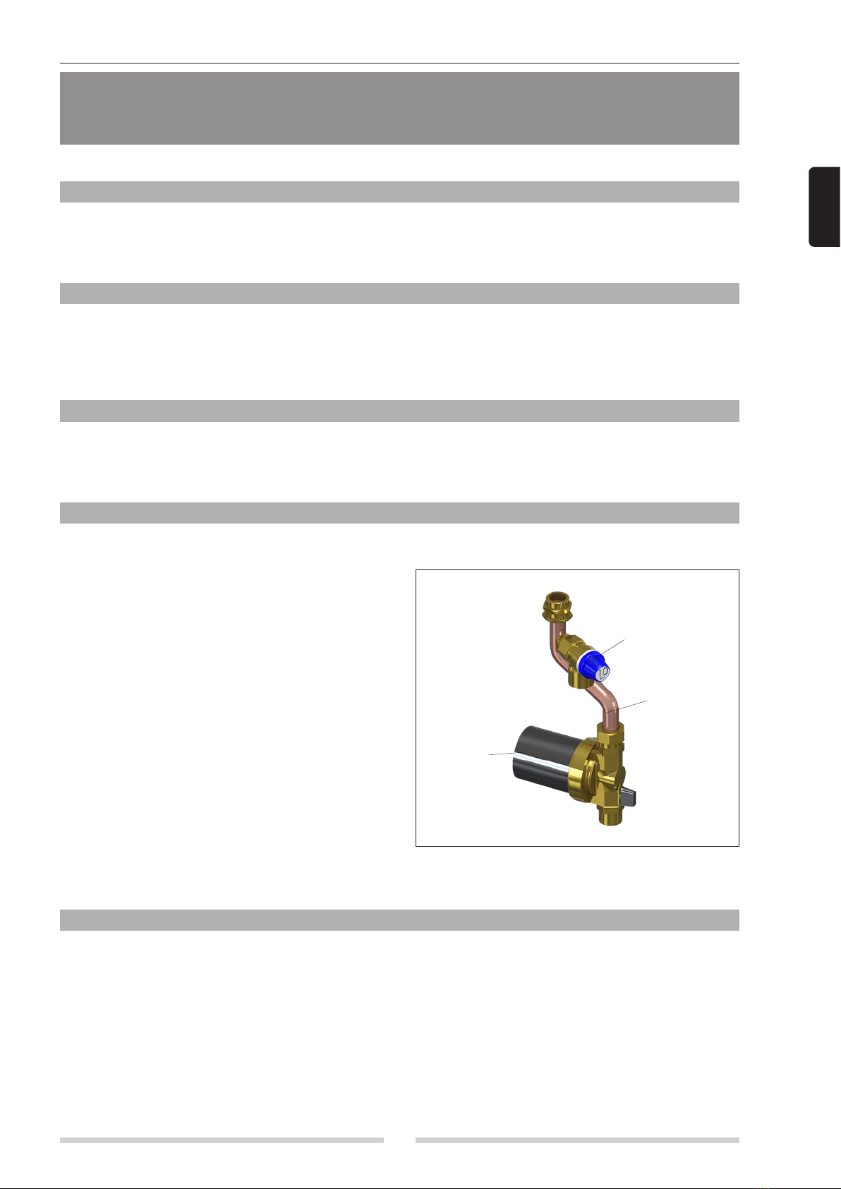
IMPOSTAZIONE DEL TERMOSTATO DI REGOLAZIONE
Selezionare la temperatura desiderata utilizzando la manopola di selezione presente sulla carcassa del motore.
La pompa si spegne automaticamente quando la temperatura dell’acqua raggiunge il valore desiderato. La temperatura
può essere impostata tra 20°C e 70°C attraverso il selettore posto sul corpo motore.
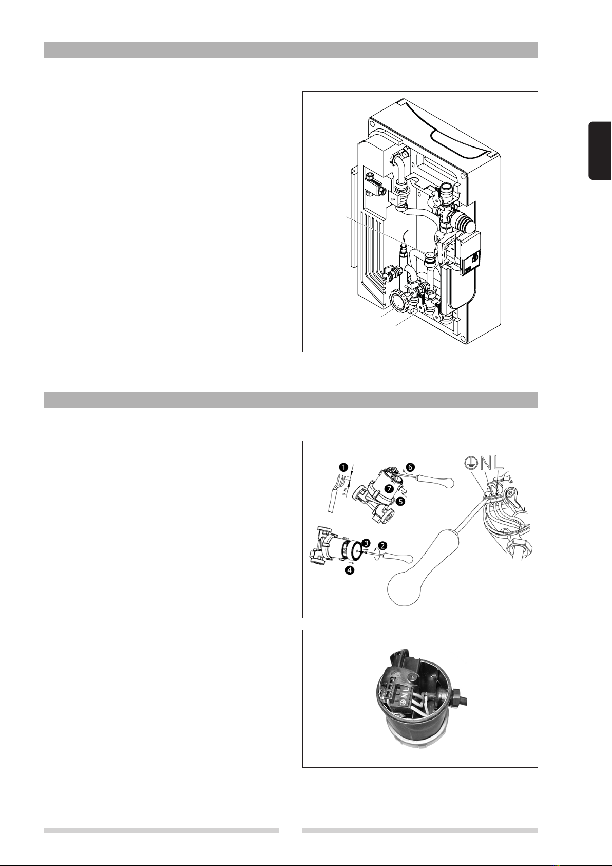
MANUTENZIONE / SMONTAGGIO
b I lavori devono essere eseguiti solo da personale specializzato.
Se la pompa si blocca o si sentono rumori di sfregamento controllare la pompa o sostituirla. A questo scopo:
- Scollegare la pompa dalla rete
- Chiudere le tubazioni di allacciamento
- Svitare il dado a risvolto ed estrarre il motore (fare in modo che non si bagni il collegamento elettrico della pompa con
la possibile fuoriuscita d’acqua).
GUASTI
Problema Causa Soluzione
La pompa non funziona Non è collegata o è collegata male Collegarla correttamente
La pompa si è surriscaldata Attendere fino al raffreddamento,
riavvio pompa automatico
Pompa bloccata Vedere il cap. MANUTENZIONE/
SMONTAGGIO
La pompa emette rumori Sfiato non sufficiente Vedere cap. MESSA IN FUNZIONE
Presenza di corpi estranei nella
pompa Vedere cap. MANUTENZIONE /
SMONTAGGIO
Cuscinetto consumato Sostituire la pompa
SMALTIMENTO
Questo prodotto e le sue parti devono essere smaltite ecologicamente rispettando le normative locali vigenti.