Sirius Satellite Radio 14250 User manual
Other Sirius Satellite Radio Antenna manuals

Sirius Satellite Radio
Sirius Satellite Radio PowerConnect XMP3I User manual

Sirius Satellite Radio
Sirius Satellite Radio SRS-2VB User manual

Sirius Satellite Radio
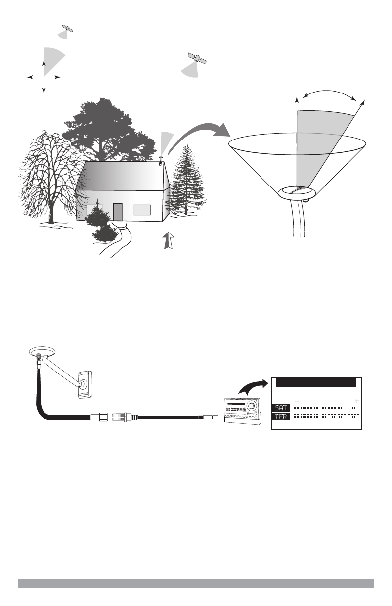
Sirius Satellite Radio SIRIUS Outdoor Home Antenna User manual

Sirius Satellite Radio
Sirius Satellite Radio Shakespeare Galaxy SRA-40 User manual

Sirius Satellite Radio
Sirius Satellite Radio Satellite Radio Antenna User manual

Sirius Satellite Radio
Sirius Satellite Radio FEA FM Extender Antenna User manual

Sirius Satellite Radio
Sirius Satellite Radio SIR-WRR1 User manual

Sirius Satellite Radio
Sirius Satellite Radio 051707a User manual

Sirius Satellite Radio
Sirius Satellite Radio FEA25 User manual

Sirius Satellite Radio
Sirius Satellite Radio 128-8662 User manual
Popular Antenna manuals by other brands

Alfa Network
Alfa Network APA-L01 Specifications

Naval
Naval PR-422CA Operation manual

Feig Electronic
Feig Electronic ID ISC.ANTH200/200 Series manual

TERK Technologies
TERK Technologies TV44 owner's manual

Directive Systems & Engineering
Directive Systems & Engineering DSE2324LYRMK quick start guide

HP
HP J8999A instructions


CommScope
CommScope CMAX-OMFX-43M-I53 Installation instruction

Ramsey Electronics
Ramsey Electronics DAP25 Kit assembly and instruction manual

COBHAM
COBHAM SAILOR 800 VSAT Replacement procedure

Trango Systems
Trango Systems AD900-9 Specification sheet

Steren
Steren ANT-100 user manual

IWCS
IWCS iriBelt II Quick start user guide