SIRS-E Pilotino WiFi PCB User manual


1. Introduction
2. Safety Information
3. Specification Characteristics
4. Onboard Features (Nomenclature)
5. Mechanical Details
6. Installation
6.1 Access Point Mode Installation
6.1.1 Basic Connection
6.1.2 Daisy Chain
6.2 Station Mode Installation
6.2.1 Basic Connection
6.2.2 Daisy Chain
6.3 Stand Alone Mode Installation
6.3.1 Basic Connection (Access point)
6.3.2 Daisy Chain (Access point)
6.3.3 Basic Connection (Station)
6.3.4 Daisy Chain (Station)
7. WiFi - Access point Mode
7.1 Basic Connection
7.2 Art-Net App Connection
8. WiFi - Station Mode
8.1 Network Connection (WPS)
8.2 IP address
8.3 Art-Net App connection
9. Default Setting
10. Mode LED Indicator
11. Hardware and Accessories
UL Certification
Pg. 3
Pg. 4
Pg. 4
Pg. 5
Pg. 6
Pg. 7
Pg. 8
Pg. 8
Pg. 9
Pg. 10
Pg. 10
Pg. 11
Pg. 12
Pg. 12
Pg. 13
Pg. 14
Pg. 15
Pg. 16
Pg. 16
Pg. 16
Pg. 17
Pg. 17
Pg. 18
Pg. 18
Pg. 19
Pg. 19
Pg. 20
Pg. 21
INDEX
2
3307 West Street Rosenberg, TX 77471 USA - (281) 324-0908
Copyright © 2006-2021 SIRS Electronics Inc. All Rights Reserved PILOTINO WiFi™ PCB Instruction Manual
Updated 09/2021. Rev 2.5

1. Introduction
One of the most important features of this product involves the onboard IO socket. This socket is
meant to be used with the PILOTINO™ PCB with onboard WiFi or capabilities. With the WiFi
module, you instantly convert this PILOTINO™ PCB into an ArtNet node receiving unit. Allowing for
a completely wireless solution.
Key Features: PILOTINO WiFi™ PCB
Compatible with any ArtNet App
Robust Wireless 2.4GHz Signal
Standalone WiFi Network
Onboard IO socket for quick integration
Wire to Board Quick Connectors
Plug and Play with Onboard IO Socket
Made in Italy with 5 Year Warranty
The PILOTINO WiFi™ PCB is the newest addition to the LED CV DMX decoder family for SIRS-E. This
version of the PILOTINO™ comes in a bare PCB format. This product is intended to be embedded into
custom fixtures and lighting control systems in which component size is critical. Equipped with four
mounting holes, the PILOTINO WiFi™ PCB is ready to be installed with M2.5 X 5mm stand-offs into any
sort of enclosure.
R
PILOTINO WiFi™ PCB
3
3307 West Street Rosenberg, TX 77471 USA - (281) 324-0908
Copyright © 2006-2021 SIRS Electronics Inc. All Rights Reserved PILOTINO WiFi™ PCB Instruction Manual
Updated 09/2021. Rev 2.5

2. Safety Information
Safety Information
3. Specification Characteristics
The exposed PCB design of this product results in a major reduction in its foot print. With a slim and narrow design, this
configuration is intended to be used in applications that would benefit from this feature. Some examples of applications
include: fixture integration, custom control enclosures, and others. The exposed design comes with few precautions to
take notice of.
The PILOTINO WiFi™ PCB is a non-waterproof device with an IP 20 rating. Keep the unit dry at all times and away from
liquids and humid environments. Make all connections to the power supply, the DMX line and the antenna prior to
powering on the circuit. All lead voltage connections to the drivers must be performed by a licensed electrician. Do not
touch any of the surfaces of the device once the unit is powered on. Ensure that all connections are secure and eliminate
allpossibilities of shorting the unit. Use the proper wire gauge for the wire to board connections. We recommend using
18 awg stranded wire for the power input, and the DMX daisy chain connection. Do not mount the unit where
vibrations or shock are present.
WiFi mode: Station/SoftAP
Security: WPA/WPA2
Encryption: WEP/TKIP/AES
Working Humidity: 0% - 90% non-condensing
IP Rating: IP 20 Non-waterproof (Keep dry)
Ventilation: Do not install in airtight spaces
Software Specification
Min current from supply: 500 mA
Working Voltage: 5V DC
Operating current: 80 mA
Operating temperature: -10 °C to 45 °C
Hardware Specifications
Frequency: 2.4 GHz - 2.5 GHz
Antenna connector: u.FL
4
3307 West Street Rosenberg, TX 77471 USA - (281) 324-0908
Copyright © 2006-2021 SIRS Electronics Inc. All Rights Reserved PILOTINO WiFi™ PCB Instruction Manual
Updated 09/2021. Rev 2.5

4. Onboard Features
1
44
442
3
6
5
7
1. I/O Connection Socket + DMX out (For PILOTINO™ PCB)
2. I/O wire to board quick connectors
3. Dip Switches to set the DMX line termination
4. Mounting holes for Standoffs M2.5 (metric)
5. Pairing button for WiFi connections
6. Mode Indicator LED
7. u.FL connector to connect a receiving Antenna
5
5
3307 West Street Rosenberg, TX 77471 USA - (281) 324-0908
Copyright © 2006-2021 SIRS Electronics Inc. All Rights Reserved PILOTINO WiFi™ PCB Instruction Manual
Updated 09/2021. Rev 2.5

5. Mechanical Details
15.84mm
PILOTINO WiFi™ PCB Top View
22.25mm
68.00mm
16.00mm
49.50mm
16.25mm
PILOTINO WiFi™ PCB Side View
6
3307 West Street Rosenberg, TX 77471 USA - (281) 324-0908
Copyright © 2006-2021 SIRS Electronics Inc. All Rights Reserved PILOTINO WiFi™ PCB Instruction Manual
Updated 09/2021. Rev 2.5

6. Installation
Standoffs
Four 2.5M x 5mm standoffs should be used to properly mount the unit onto a smooth and level surface. It is recommended
that the included factory 2.5M stand offs be used. To fasten the PILOTINO WiFi™ PCB onto a surface, first screw the four
screws in a crisscross pattern. To tighten the screws, torqued them down to ¼ turn past hand tight, again in a crisscross
pattern. Always tighten the screw opposite to the last screw that was torqued down. Do not over tighten the screws as doing
so will result in damage to the device.
Clearance
Due to the exposed contact points on the PILOTINO WiFi™ PCB, the risk of shorting the unit should be considered. A minimum
of 10mm of clearance space is recommended. Never install the PILOTINO WiFi™ PCB within an enclosed space in which the
PILOTINO WiFi™ PCB does not have sufficient space away from other components.
Connections
The PILOTINO WiFi™ PCB comes equipped with wire to board quick connectors, and a socket connector to connect to the
PILOTINO™ PCB . Properly connect the PILOTINO WiFi™ PCB to the PILOTINO™ PCB with the boards facing the same direction.
All wire connections should fit securely into the connectors. Be sure to insert each wire into the connectors deep enough so
that no bare wire is exposed. A good rule of thumb is to strip the wires so that only about 3mm of insulation is removed.
To have the best network connection, place the PILOTINO WiFi™ PCB in a location where the antenna has a clear line of
sight from the device connected to.
7
3307 West Street Rosenberg, TX 77471 USA - (281) 324-0908
Copyright © 2006-2021 SIRS Electronics Inc. All Rights Reserved PILOTINO WiFi™ PCB Instruction Manual
Updated 09/2021. Rev 2.5
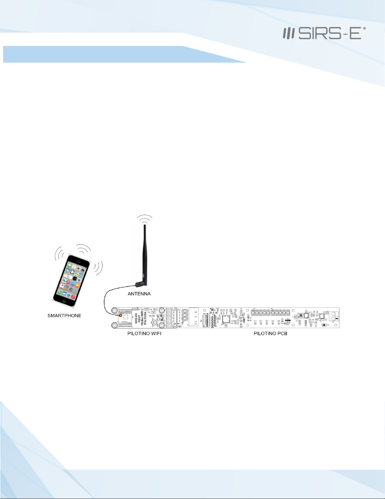
6.1 Access Point Mode Installation
6.1.1 Basic Connection
Make sure the PILOTINO WiFi™ PCB and antenna are connected to the PILOTINO™ PCB.
Power on the PILOTINO™ PCB board once proper wiring connections are done to eliminate
short circuiting the board.
With the smartphone device, go to the “Settings -> WiFi/Network -> PilotWiFi_####, where #### is a
random sequence of four numbers.
When first prompted for a password, type PilotWiFi_0000.
Use any Art-Net IOS or Android App to drive the PILOTINO™ PCB.
8
3307 West Street Rosenberg, TX 77471 USA - (281) 324-0908
Copyright © 2006-2021 SIRS Electronics Inc. All Rights Reserved PILOTINO WiFi™ PCB Instruction Manual
Updated 09/2021. Rev 2.5
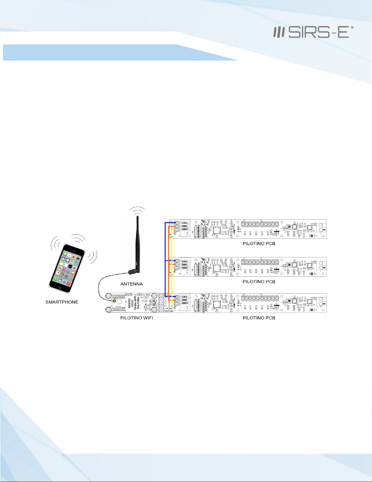
6.1 Access Point Mode Installation
6.1.2 Daisy Chain
Make sure the PILOTINO WiFi™ PCB and antenna are connected to the PILOTINO™ PCB.
Connect the DMX IN/OUT wires to each of the PILOTINO™ PCB boards in a sequence, similar
to a daisy flower ring, to each corresponding connector.
Power on the PILOTINO™ PCB boards once proper wiring connections are done to eliminate
short circuiting the boards.
With the smartphone device, go to the “Settings -> WiFi/Network -> PilotWiFi_####, where #### is a
random sequence of four numbers.
When first prompted for a password, type PilotWiFi_0000.
Use any Art-Net iOS or Android App to drive the PILOTINO™ PCB.
9
3307 West Street Rosenberg, TX 77471 USA - (281) 324-0908
Copyright © 2006-2021 SIRS Electronics Inc. All Rights Reserved PILOTINO WiFi™ PCB Instruction Manual
Updated 09/2021. Rev 2.5

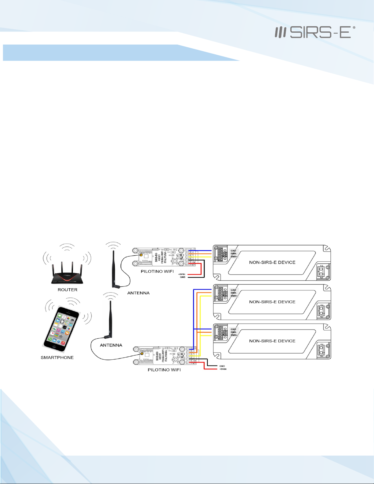
6.2 Station Mode Installation
6.2.1 Basic Connection
Make sure when connecting each PILOTINO WiFi™ PCB and antenna to a PILOTINO™ PCB.
Power on the PILOTINO™ PCB boards once proper wiring connections are done to eliminate
short circuiting the boards.
Connect the PILOTINO WiFi™ PCB to a router by a WPS procedure (for more details see chapter 8.1).
Also, connect the smartphone to the router and use any Art-Net iOS or Android App to drive each
PILOTINO™ PCB.
10
PILOTINO WiFi™ PCB Instruction Manual
Updated 09/2021. Rev 2.5
3307 West Street Rosenberg, TX 77471 USA - (281) 324-0908
Copyright © 2006-2021 SIRS Electronics Inc. All Rights Reserved

6.2 Station Mode Installation (cont.)
6.2.2 Daisy Chain
Make sure the PILOTINO WiFi™ PCB and antenna are connected to the PILOTINO™ PCB
that is used individually and another PILOTINO™ PCB that is being daisy chained.
Connect the DMX IN/OUT wires to each of the PILOTINO™ PCB boards in a sequence, similar
to a daisy flower ring, to each corresponding connector that are being daisy chained.
Power on the PILOTINO™ PCB boards once proper wiring connections are done to eliminate
short circuiting the boards.
Connect the PILOTINO WiFi™ PCB to a router by a WPS procedure (for more details see chapter 8.1).
Also connect the smartphone to the router and use any Art-Net iOS or Android App to drive each
PILOTINO™ PCB.
11
PILOTINO WiFi™ PCB Instruction Manual
Updated 09/2021. Rev 2.5
3307 West Street Rosenberg, TX 77471 USA - (281) 324-0908
Copyright © 2006-2021 SIRS Electronics Inc. All Rights Reserved
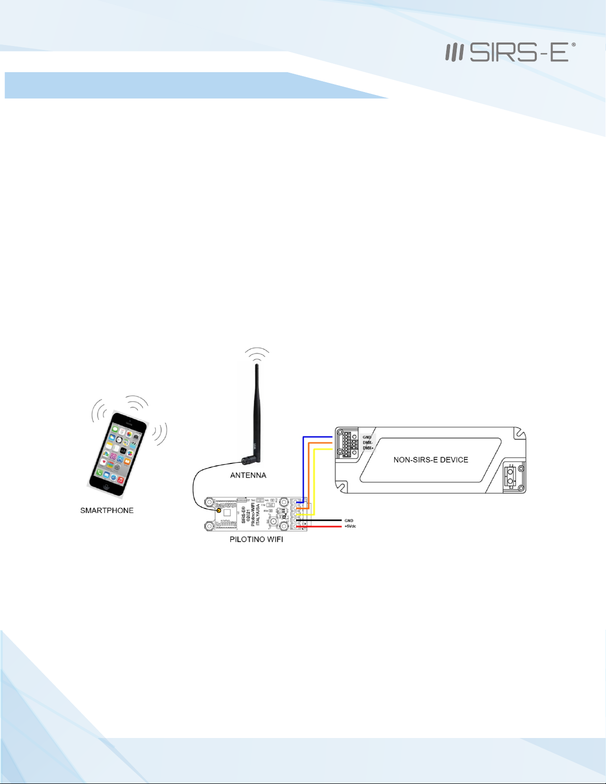
6.3 Stand Alone Mode Installation
6.3.1 Basic Connection (Access Point)
Make sure the PILOTINO WiFi™ PCB and antenna are connected to a power source (5 Vdc).
Properly connect the PILOTINO WiFi™ PCB to a DMX Driver utilizing the DMX IN/OUT connectors.
Power on the PILOTINO WiFi™ PCB once proper wiring connections are done to eliminate
short circuiting the boards or controller.
With the smartphone device, go to the “Settings -> WiFi/Network -> PilotWiFi_####, where #### is a
random sequence of four numbers.
When first prompted for a password, type PilotWiFi_0000.
Use any Art-Net iOS or Android App to drive the DMX device.
12
PILOTINO WiFi™ PCB Instruction Manual
Updated 09/2021. Rev 2.5
3307 West Street Rosenberg, TX 77471 USA - (281) 324-0908
Copyright © 2006-2021 SIRS Electronics Inc. All Rights Reserved

6.3 Stand Alone Mode Installation (cont.)
6.3.2 Daisy Chain (Access Point)
Make sure the PILOTINO WiFi™ PCB and antenna are connected to a power source (5 Vdc).
Connect the DMX IN/OUT wires to each of the DMX Drivers in a sequence, similar to a daisy flower ring, to
each corresponding connector.
Power on the PILOTINO WiFi™ PCB once proper wiring connections are done to eliminate short circuiting the
boards or controllers.
With the smartphone device, go to the “Settings -> WiFi/Network -> PilotWiFi_####, where #### is a
random sequence of four numbers.
When first prompted for a password, type PilotWiFi_0000.
Use any Art-Net iOS or Android App to drive the DMX devices.
13
PILOTINO WiFi™ PCB Instruction Manual
Updated 09/2021. Rev 2.5
3307 West Street Rosenberg, TX 77471 USA - (281) 324-0908
Copyright © 2006-2021 SIRS Electronics Inc. All Rights Reserved
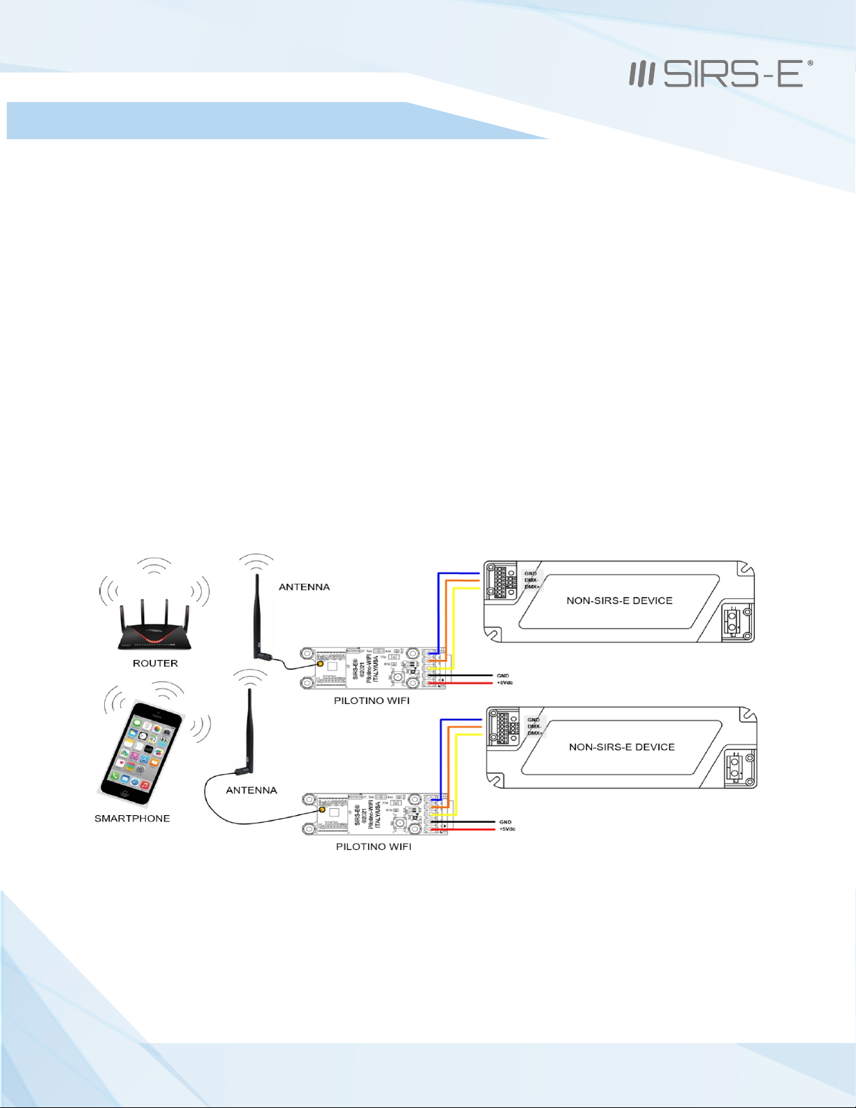
6.3 Stand Alone Mode Installation (cont.)
6.3.3 Basic Connection (Station)
Make sure each PILOTINO WiFi™ PCB and antenna are connected to a power source (5 Vdc).
Properly connect each PILOTINO WiFi™ PCB to a DMX Driver utilizing the DMX IN/OUT connectors.
Power on the PILOTINO WiFi™ PCB once proper wiring connections are done to eliminate
short circuiting the boards.
Connect each PILOTINO WiFi™ PCB to the same router by a WPS procedure (for more details see chapter 8.1).
Also connect the smartphone to the router and use any Art-Net iOS or Android App to drive each DMX
device.
14
PILOTINO WiFi™ PCB Instruction Manual
Updated 09/2021. Rev 2.5
3307 West Street Rosenberg, TX 77471 USA - (281) 324-0908
Copyright © 2006-2021 SIRS Electronics Inc. All Rights Reserved
6.3 Stand Alone Mode Installation (cont.)
6.3.4 Daisy Chain (Station)
Make sure the PILOTINO WiFi™ PCB and antenna are connected to a power source (5 Vdc).
Connect the DMX IN/OUT wires to each of the DMX Drivers boards in a sequence, similar
to a daisy flower ring, to each corresponding connector.
Power on the PILOTINO WiFi™ PCB once proper wiring connections are done to eliminate
short circuiting the boards or controllers.
Connect each PILOTINO WiFi™ PCB to the same router by WPS procedure (for more details see chapter 8.1)
Also connect the smartphone to the router and use any Art-Net iOS or Android App to drive each DMX
device.
15
PILOTINO WiFi™ PCB Instruction Manual
Updated 09/2021. Rev 2.5
3307 West Street Rosenberg, TX 77471 USA - (281) 324-0908
Copyright © 2006-2021 SIRS Electronics Inc. All Rights Reserved

The Access Point (default mode) is the PILOTINO WiFi™ PCB acting as its own network. A cyan indicator LED turns steady
on the PILOTINO WiFi™ PCB. This allows for a complete wireless solution for a smartphone to act as a DMX controller.
7. Wi-Fi - Access Point Mode
7.1 Basic Connection
7.1 Basic Connection
7.1 Network Connection
7.2 Art-Net App Connection
Art-Net App works on any compatible IOS or Android
When connecting the Art-Net App, make sure that the device being used is connected to the same WiFi network
that the PILOTINO WiFi™ PCB is broadcasting
After setting up the App on the smartphone device, a cyan indicator LED on the PILOTINO WiFi™ PCB will blink slowly
Art-Net signal present!
After turning on the power to the PILOTINO WiFi™ PCB, a green indicator LED turns steady.
After a few seconds, the indicator LED turns from green to cyan; the PILOTINO™’s internal WiFi network is
now ready to pair.
With the smartphone device, go to the “Settings -> WiFi/Network -> PilotWiFi_####, where #### is a
random sequence of four numbers.
When first prompted for a password, type PilotWiFi_0000
16
PILOTINO WiFi™ PCB Instruction Manual
Updated 09/2021. Rev 2.5
3307 West Street Rosenberg, TX 77471 USA - (281) 324-0908
Copyright © 2006-2021 SIRS Electronics Inc. All Rights Reserved

8. Wi-Fi - Station Mode
8.1 Network Connection (WPS)
The Station mode is when the PILOTINO WiFi™ PCB connects to a near by wireless internet router. A blue indicator LED
on the PILOTINO WiFi™ PCB turns steady. This allows for a complete wireless solution for a smartphone to act as a DMX
controller. With the Station Mode, the router can connect to multiple PILOTINO WiFi™ PCB with a combination of basic
connection and daisy chain connections. Very user friendly when working on different projects from residential to a
business., or personal use.
After turning on the power to the PILOTINO WiFi™ PCB, a green indicator LED turns steady.
After a few seconds, the indicator LED turns from green to cyan; the PILOTINO™’s internal WiFi network is ready
to pair.
On a near by wireless router, press the WPS button to initialized scanning for new devices.
Locate the paring button, on the PILOTINO WiFi™ PCB, then press and hold the button until the LED
changes color, from cyan to white.
A steady blue indicator LED is shown on the PILOTINO WiFi™ PCB representing a successful connection
with a wireless router.
A slow flashing white indicator LED is shown on the PILOTINO WiFi™ PCB representing a failed connection
with a wireless router. In this case, repeat the WPS procedure.
Perform the same operation for all PILOTINO WiFi™ PCB
17
PILOTINO WiFi™ PCB Instruction Manual
Updated 09/2021. Rev 2.5
3307 West Street Rosenberg, TX 77471 USA - (281) 324-0908
Copyright © 2006-2021 SIRS Electronics Inc. All Rights Reserved

8.2 IP Address
8.3 Art-Net App Connection
Art-Net App works on any compatible IOS or Android
Configure the WiFi settings and connect the smartphone device to the router in which will be connected on the
same network as the PILOTINO WiFi™ PCB.
Launch an application on the smartphone device that has configuration with Art-Net
After setting up the App on the smartphone device, a blue indicator LED on the PILOTINO WiFi™ PCB will blink slowly:
Art-Net signal present!
The IP addresses are an identifier assigned from the router and are required for connecting devices to
access the network.
On a computer or smartphone device, access the Network & Internet settings and locate the PILOTINO WiFi™ PCB
IP settings in the properties section to correctly set the Art-Net App.
Note: PILOTINO WiFi™ PCB support only a DHCP protocol.
18
PILOTINO WiFi™ PCB Instruction Manual
Updated 09/2021. Rev 2.5
3307 West Street Rosenberg, TX 77471 USA - (281) 324-0908
Copyright © 2006-2021 SIRS Electronics Inc. All Rights Reserved

9. Default Setting
To return the PILOTINO WiFi™ PCB to the default settings, press and hold the pairing button, for about 10
seconds, until the indicator LED turns green and has blinked once.
The indicator LED will turn cyan after a few seconds to indicate the PILOTINO WiFi™ PCB is acting as an access point
10. Mode LED Indicator
- Green Led Static: Power ON
- Cyan LED static: PILOTINO WiFi™ PCB working with the internal network
- Cyan LED slow blinking: Art-Net or sCAN signal present
- Blue LED static: Module connected to an external WiFi network
- Blue LED slow blinking: Art-Net or sACN signal present
- Blue LED fast blinking: Module disconnected from the external WiFi network
- White LED static: WPS connection
- White LED slow blinking: WPS connection failed
- Yellow LED: DMX signal present on J1 and J3 connector
19
PILOTINO WiFi™ PCB Instruction Manual
Updated 09/2021. Rev 2.5
3307 West Street Rosenberg, TX 77471 USA - (281) 324-0908
Copyright © 2006-2021 SIRS Electronics Inc. All Rights Reserved

11. Hardware and Accesories
The expansion modules to equip the with onboard WiFi capabilities can be instantlyPILOTINO™ PCB
converted into an ArtNet node receiving unit. The has an ANT pin to connect a PILOTINO WiFi™ PCB
receiving Antenna opposite from the IO socket.
Key Features:
RP-TNC external antenna connector
2dBi Omni Antenna, TimoTwo
OEM Coax cable IPEX to RP-TNC, 15 cm
50 ohm at 2.45 Ghz
3307 West St.
Rosenberg , Texas 77471
Phone: 281-324-0908
www.sirs-e.com
20
PILOTINO WiFi™ PCB Instruction Manual
Updated 09/2021. Rev 2.5
3307 West Street Rosenberg, TX 77471 USA - (281) 324-0908
Copyright © 2006-2021 SIRS Electronics Inc. All Rights Reserved
Other manuals for Pilotino WiFi PCB
1
Table of contents
Other SIRS-E Lighting Equipment manuals

Popular Lighting Equipment manuals by other brands

Modulex
Modulex SX-LN131 Mounting installation guide

Perel
Perel NUCLILED 144 user manual

Whelen Engineering Company
Whelen Engineering Company 14660 installation guide

STL
STL K-FORCE TOW 55 instruction manual

KAM
KAM Laserscan 300 3D instruction manual

Code 3
Code 3 DashLaser 660 Installation & operation manual


