manuals.online logo
Brands
  1. Home
  2. •
  3. Brands
  4. •
  5. Sister Bay
  6. •
  7. Outdoor Furnishing
  8. •
  9. Sister Bay HYANNIS DOUBLE GLIDER User manual

Sister Bay HYANNIS DOUBLE GLIDER User manual

(4)
2.75
2.50
B
(11)
A(4)
3.50
G(4)
C
1.25
(4)
F1 (4)
(4)
D1
E2
(8)D2
(4)
E1
F2 (4)
M
Seat Bottom
Assembly
Glider Left Base
Assembly
Right Arm Leg
Assembly
2.50
(8)
1.50
G2 (16)
G1
Seat Back
Assembly
I
Under Arm
Brace
H
Glider Right
Base
Assembly
P
Glider Base Middle
Brace Front & Back
K
Arm
L
Left Leg
Assembly
Q
N
J
Assembly Instructions
Do not use
any hand drill
on this product
WRENCH
( not included )
ALLEN WRENCH
( included )
You will also need a phillips-head screwdriver
( not included )
Hardware and Parts
Item No: MHYA-G-D-R
HYANNIS DOUBLE GLIDER
Item No: MYAR-G-D-R
YARMOUTH DOUBLE GLIDER
Right side
Front Leg (FR)
(identification marks
facing up)
J
Under Arm
brace
G1
FRONT
Right side
Rear Leg (RR)
(identification
marks
facing up)
J
1a - Attach part ( K ) under arm brace to part ( J ) front right side ( FR ) & Rear right side ( RR ) legs using 4 of screws.
( G1 ) 2 for each leg. Tighten screws using a phillips-head screwdriver. Be sure to lay the legs and arm brace on
a flat clean surface to assemble. Line up the front right leg ( FR ) with the front of the arm brace ( 2 screws ),
line up the rear right side leg ( RR ) with the back of the arm brace (1 screw). Make sure the identification marks
FR & RR are facing upward. Follow the same instructions for left side legs ( Q ), the identification marks FL & RL
should be facing down. Leg and arm brace assembly should form an "A" frame if done correctly.
1b - To Attach part ( J ) , Right
leg Assembly
to part ( L ) arm, lay arm face down on a flat clean surface, place ( J )
right side leg assembly over the arm using ( 6 ) of screw ( G2 ) tighten screws using a phillips-head screwdriver.
Follow the same instructions for left side legs ( Q ).
FR
RR
FR
RR
K
Right side
Rear Leg (RR)
(identification marks
facing up)
J
Right side
Front Leg (FR)
(identification marks
facing up)
J
Figure 1
Left side
Front Leg (FL)
(identification marks
facing down)
Q
Under Arm
brace
G1
FRONT
K
Q
Left side
Rear Leg (RL)
(identification marks
facing down)
G2
Left side
Rear Leg (RR)
(identification marks
facing down)
Under Arm
brace
FRONT
K
Left side
Front Leg (FR)
(identification
marks
facing down)
BACK
Arm
L
Q
Q
1b
1a
G2
Under Arm
brace
FRONT
K
BACK
Arm
L
O
( Back Aluminum cover )
2 c - Attach part ( O ) ,
Back Aluminum cover
, to Assembly
from figure 2, as shown in detail 2 , using ( 4 ) of screw
( G ), and tighten screws using a phillips-head screwdriver.
G
Figure 2
( Detail 2 )
3 - Attach parts ( M ) ,
Glider Base Mid Brace Front & Back
, to parts ( P ),
Glider Right Base Assembly and part (N)
Glider Left Base Assembly,
as shown in Figure 3 see detail 3 using ( 8 ) of screw ( C ), 4 on each side and tighten
screws using an allen Wrench .
Figure 3
( Glider Base Mid brace
Front & Back )
( Glider Right base
Assembly)
( Glider Left base
Assembly)
( Detail 3 )
M
P
C
N
Front edge
of groove
Front edge of Yoke
2,b - Attach part ( H ) ,
Seat Back Assembly
, to part ( I ),
Seat Bottom Assembly
, as shown in Figure 2
see detail 1 using ( 4 ) of screws ( G2 ) , 2 on each side,
tighten screws using a phillips-head screwdriver . Also
(1) screw of ( C ), in center as shown, tighten
screw using an allen wrench.
2,a - Attach part ( H ) ,
Seat Back Assembly
, to part ( I ),
Seat Bottom Assembly
you must align the lower
front edge of Yoke to hide the front edge of groove,
see detail 1 .
( Seat Bottom )
Assembly
I
( Seat Back)
Assembly
H
( Detail 1 )
C
G2
Figure 4
Figure 5
5 - Attach the
Assembly from figure
4, ( Glider Seat ) to Assembly from Figure 3, ( Glider Base ) as shown in Figure 5
see detail 7
using for each leg ( 1 ) of joint connector bolts ( B ) , ( 2 ) washers ( D2 ),( 1 ) Lock washers ( E2 ) and
( 1 ) hex nuts ( F2 ), tighten bolts using an allen Wrench and also an adjustable wrench.
B
D2 E2
F2
( Detail 7 )
( Detail 6 )
( Seat Back
Assembly )
( Detail 5 )
D1
E1
F1
identification marks
(Right side
leg Assembly )
(FR) (RR)
( Detail 4 )
(FR)
4,a - Attach part ( J ) ,
Right side front and rear leg assembly
,
to
assembly from
Figure 2 as shown in Figure 4, Make sure identification marks ( FR ) and ( RR )
are facing inside towards the seat see detail 4, using ( 2 ) of joint connector
bolts ( A ), ( 2 ) washers ( D1 ), ( 2 ) lock washers ( E1 ), ( 2 ) hex nuts ( F1 ), see
detail 5 tighten bolts using an Allen wrench and also an adjustable wrench.
Follow the same instructions for left side front and rear leg assembly.
4,b - Attach part ( J ), Right side front and rear leg and part to seat
back assembly ( H ), as shown in Figure 4, see detail 6, using
( 1 ) of lag screws ( C ), tighten screws using and allen wrench.
Follow the same instructions for left side front and rear leg assembly.
A
AC
C
H
AC
J
CARE AND MAINTENANCE
To clean your product, use mild soap and water. For heavy soil build-ups use any non-abrasive household cleaners
or ask your Sales Representative about Sister Bay Furniture Cleaner.
Please contact our Customer Service Department for assembly assistance, questions or replacement parts at 1-866-947-7632
or email [email protected]. Our Customer Service Department is available Monday - Friday from 8:30 a.m. to 4:30 p.m. EST

This manual suits for next models

3

Other Sister Bay Outdoor Furnishing manuals
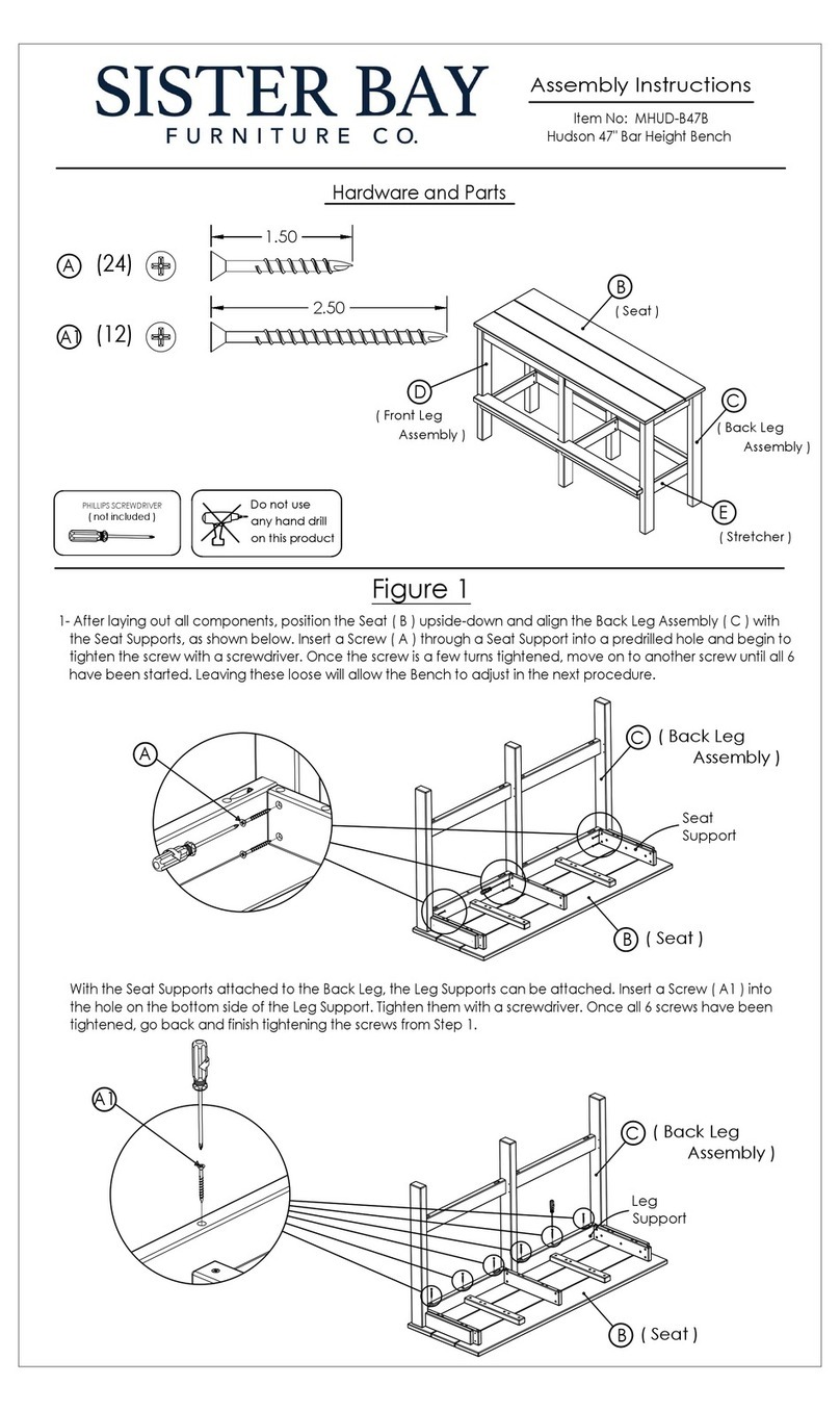
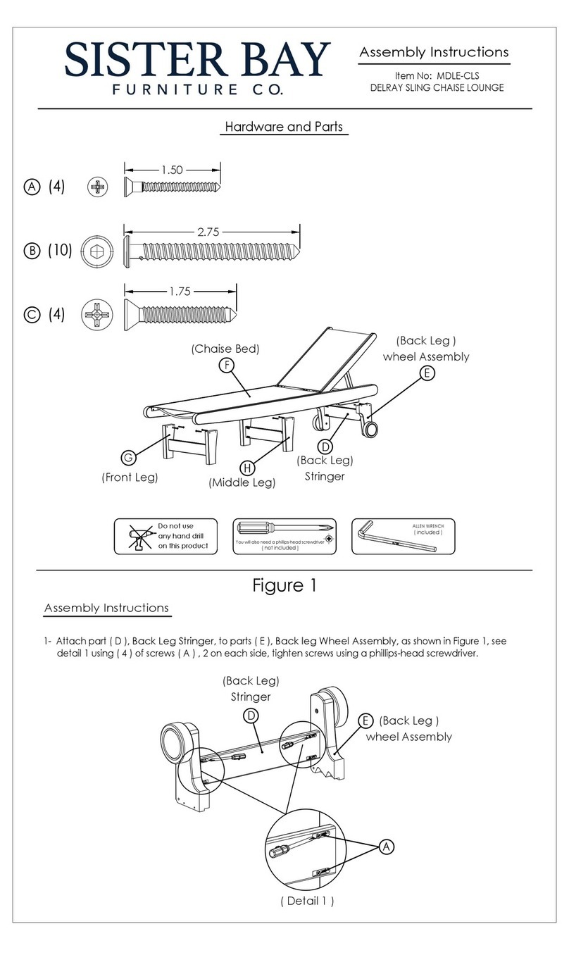
Sister Bay Hudson MHUD-B47B User manual
Sister Bay

Sister Bay Hudson MHUD-B47B User manual

Sister Bay MDLE-CLS User manual

Sister Bay

Sister Bay MDLE-CLS User manual
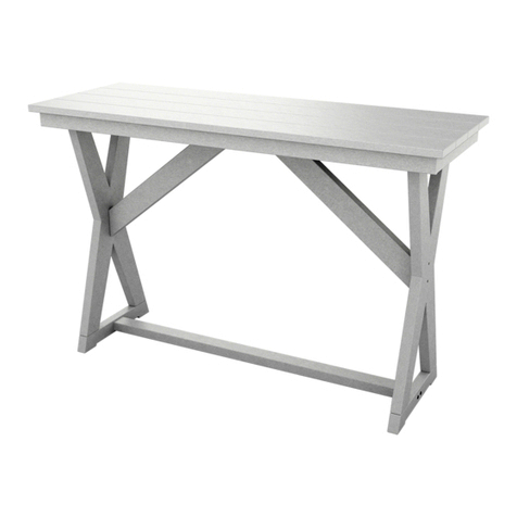
Sister Bay MHUD-DT60B User manual

Sister Bay

Sister Bay MHUD-DT60B User manual

Sister Bay MSUM-A-R User manual

Sister Bay

Sister Bay MSUM-A-R User manual
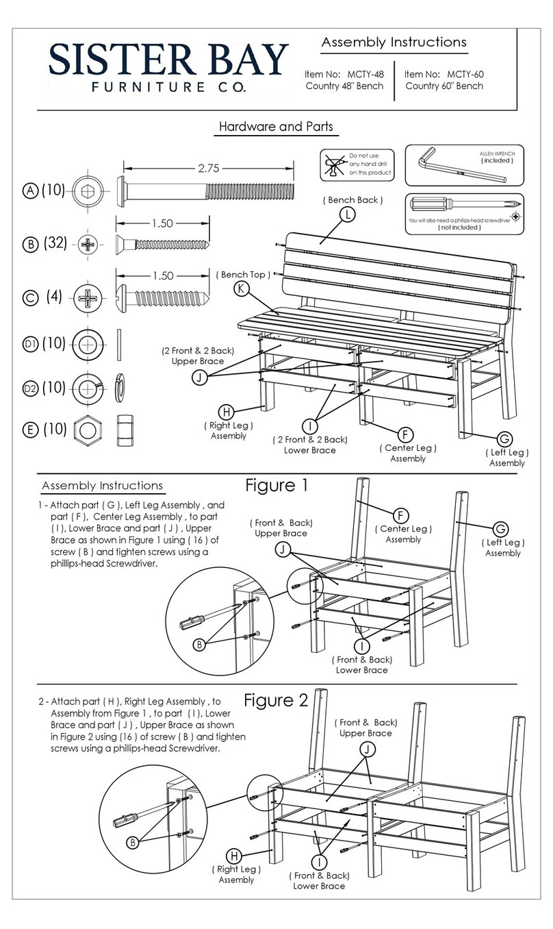
Sister Bay MCTY-48 User manual

Sister Bay

Sister Bay MCTY-48 User manual
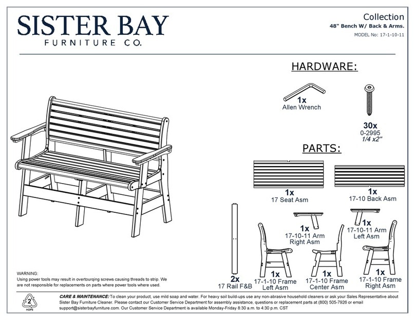
Sister Bay 17-1-10-11 User manual

Sister Bay

Sister Bay 17-1-10-11 User manual
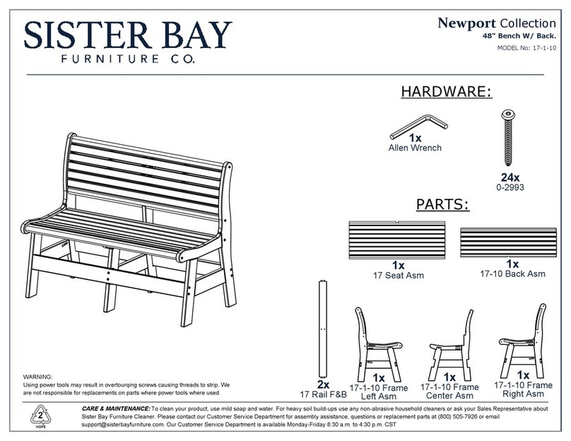
Sister Bay Newport 17-1-10 User manual
Sister Bay

Sister Bay Newport 17-1-10 User manual

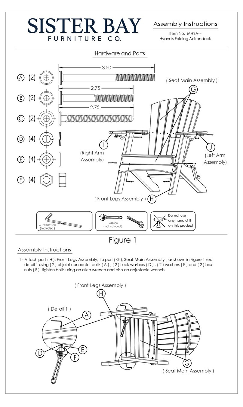
Sister Bay MHYA-F User manual

Sister Bay

Sister Bay MHYA-F User manual

Popular Outdoor Furnishing manuals by other brands

PHI VILLA THD5-0601-344B Use and care guide

PHI VILLA

PHI VILLA THD5-0601-344B Use and care guide

PHI VILLA THD-E048-01 Use and care guide
PHI VILLA

PHI VILLA THD-E048-01 Use and care guide

Sunjoy A111302500 Assembly instruction

Sunjoy

Sunjoy A111302500 Assembly instruction

Hanover TRADDN9PCSWSQ-8 manual

Hanover

Hanover TRADDN9PCSWSQ-8 manual
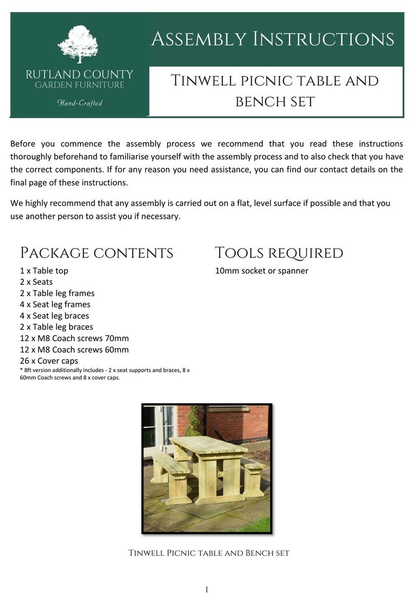
Rutland County Garden Furniture Tinwell picnic table and bench set Assembly instructions

Rutland County Garden Furniture

Rutland County Garden Furniture Tinwell picnic table and bench set Assembly instructions
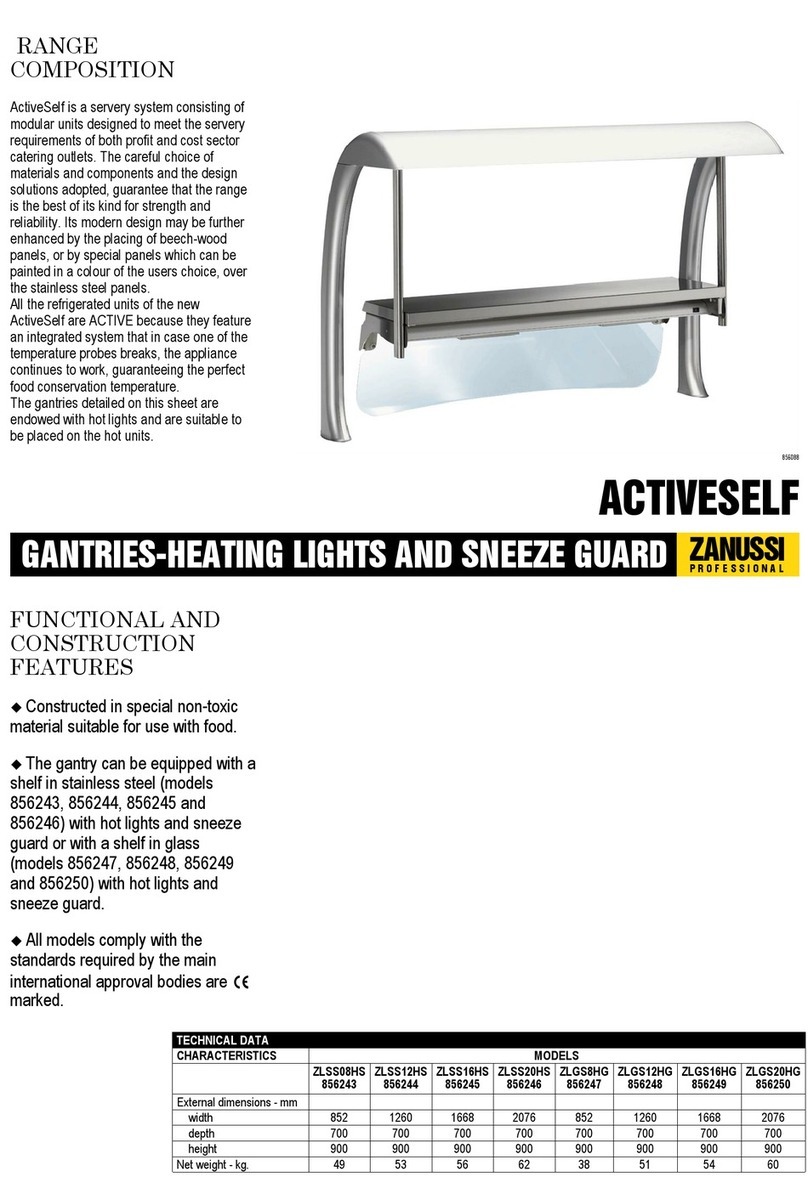
Zanussi ZLGS12HG 856248 Brochure & specs
Zanussi

Zanussi ZLGS12HG 856248 Brochure & specs

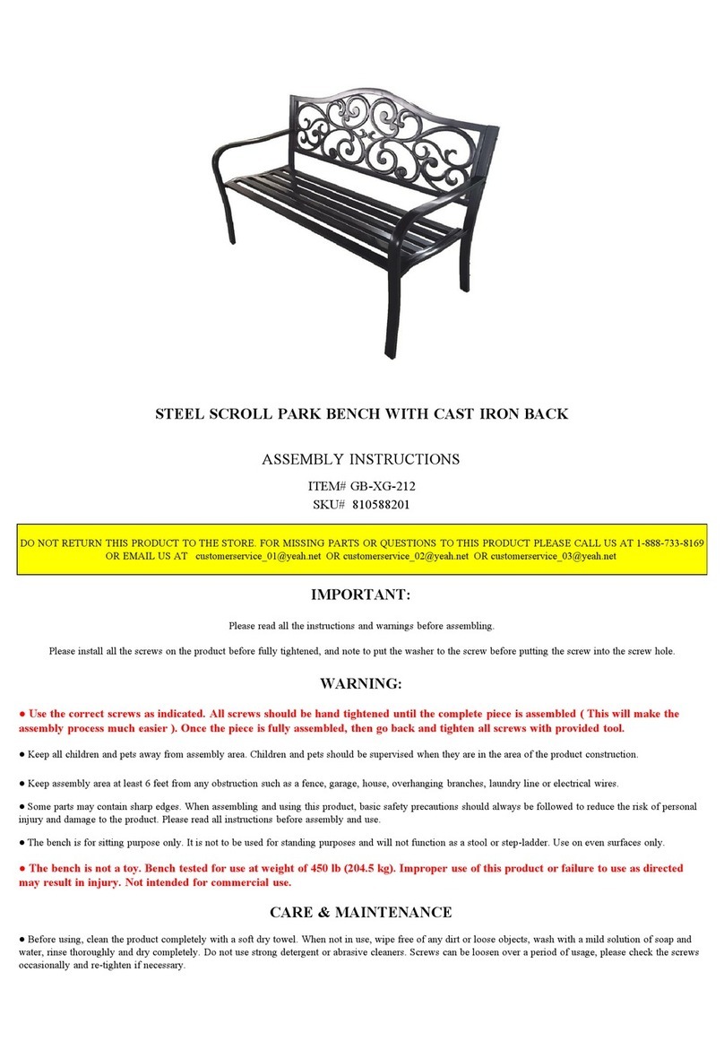
real living GB-XG-212 Assembly instructions
real living

real living GB-XG-212 Assembly instructions

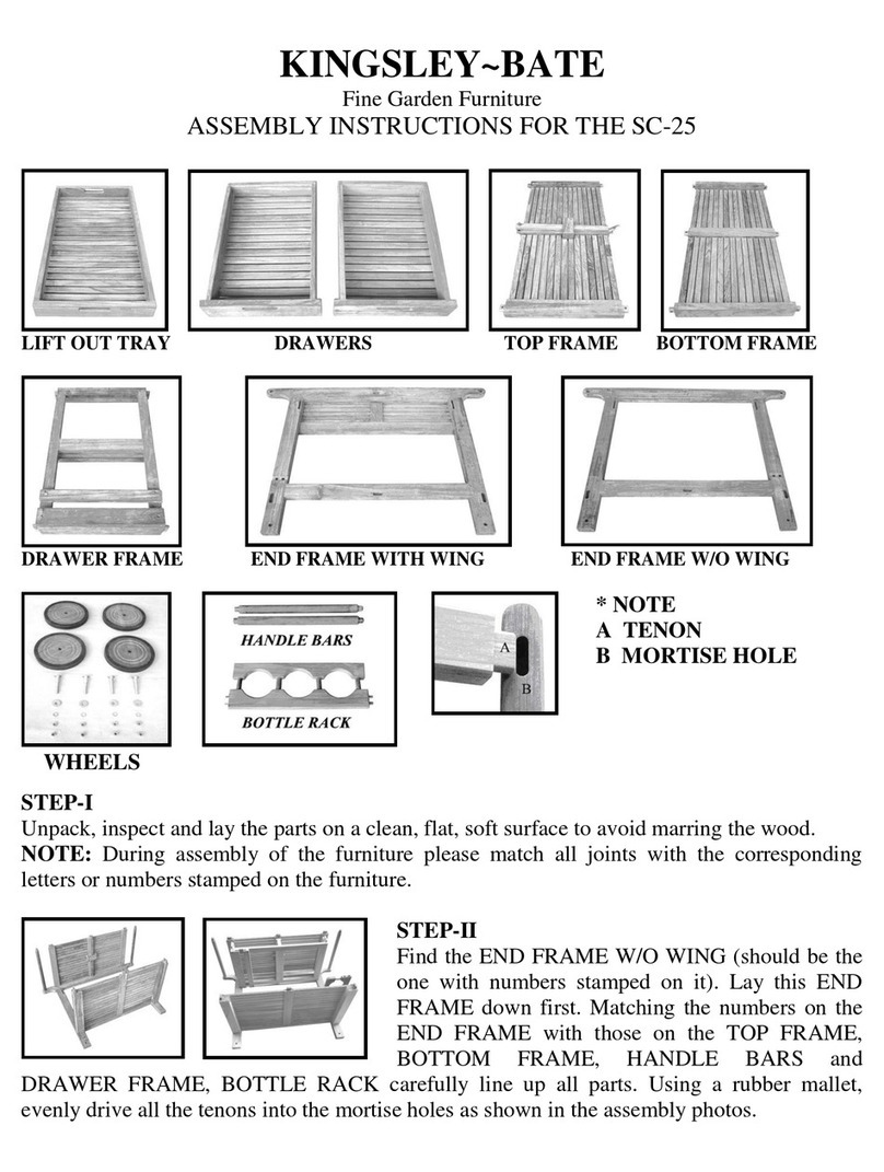
kingsley-bate SC-25 Assembly instructions
kingsley-bate

kingsley-bate SC-25 Assembly instructions

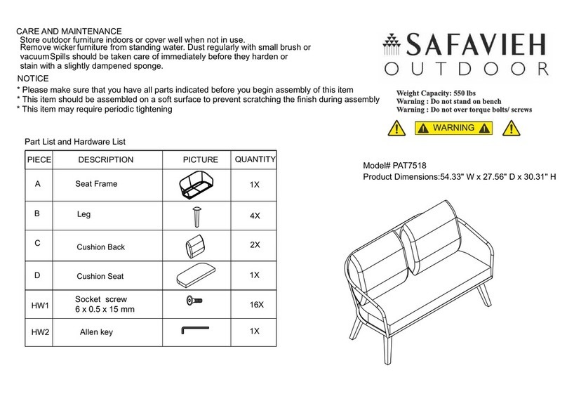
Safavieh Outdoor Jorda PAT7518B manual
Safavieh Outdoor

Safavieh Outdoor Jorda PAT7518B manual

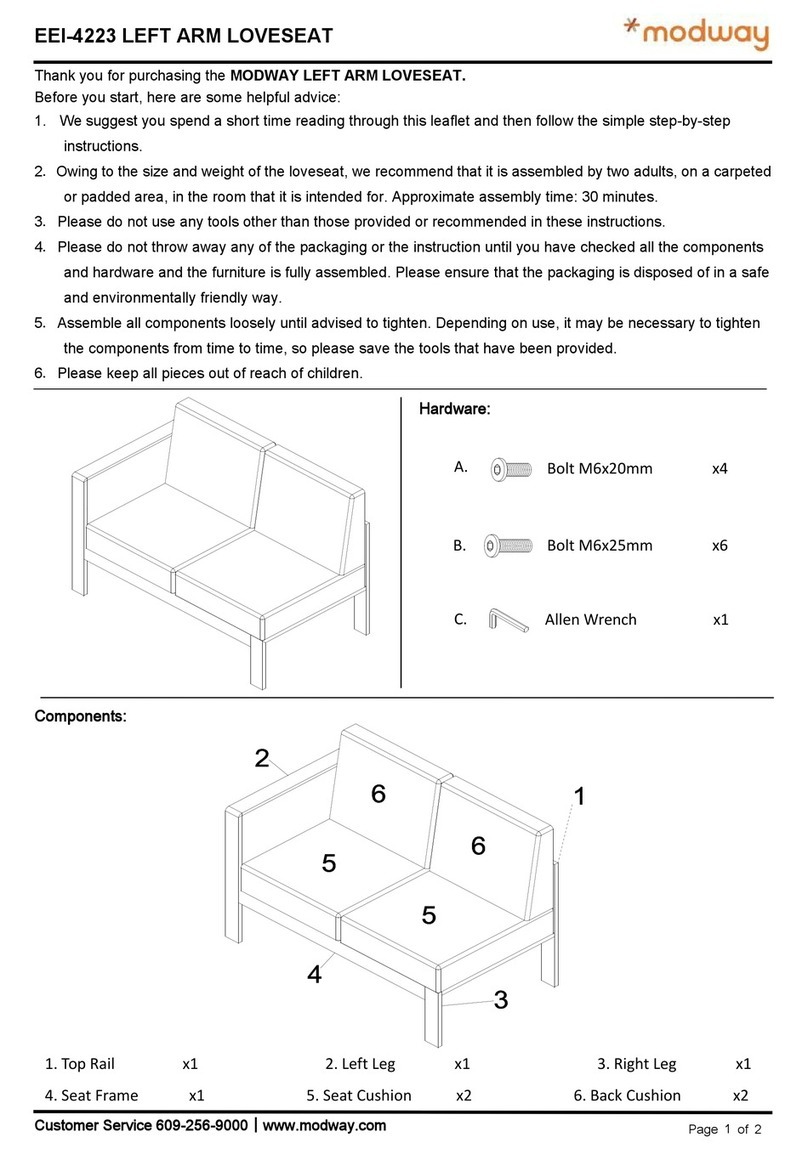
modway EEI-4223 manual

modway

modway EEI-4223 manual

Allen + Roth TPGAZ2241 Assembly instructions
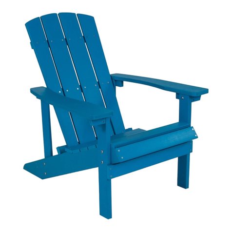
Allen + Roth

Allen + Roth TPGAZ2241 Assembly instructions

Flash Furniture JJ-C14501-BLU-GG Assembly instructions

Flash Furniture

Flash Furniture JJ-C14501-BLU-GG Assembly instructions

Pragma Axi NICK instruction manual

Pragma

Pragma Axi NICK instruction manual

dellonda DG59 quick start guide

dellonda

dellonda DG59 quick start guide

Westin Outdoor OP8007 instruction manual

Westin Outdoor

Westin Outdoor OP8007 instruction manual

Costway HW66352 user manual

Costway

Costway HW66352 user manual

GRAND RESORT D71 M56693 Use and care guide

GRAND RESORT

GRAND RESORT D71 M56693 Use and care guide

Weltevree Forestry bench refined 3P product manual

Weltevree

Weltevree Forestry bench refined 3P product manual

manuals.online logo
manuals.online logoBrands
  • About & Mission
  • Contact us
  • Privacy Policy
  • Terms and Conditions

Copyright 2025 Manuals.Online. All Rights Reserved.