Sisyph SMB10 User manual

User's Guide
SMB10
Garonne
Phase/Frequency Discriminator
SISYPH
Signals & Systems for Physics
www.sisyph.com

User's Guide
SMB10-SN03-P22A
SMB10
Garonne
Phase/Frequency Discriminator
Contents
1 Scope 3
2 Overview 3
3 Operation 3
3.1 Frontpanel .............................................. 3
3.1.1 Beat-NoteInput ....................................... 3
3.1.2 SynchronizationInput.................................... 4
3.1.3 Beat-NoteMonitor...................................... 4
3.1.4 PhaseErrorMonitor..................................... 4
3.2 BusHeadersConnections ...................................... 4
3.2.1 PhaseErrorOutput ..................................... 4
3.2.2 SignalGround ........................................ 4
3.2.3 Lock-DetectOutput ..................................... 4
3.2.4 Acquire/TrackOutput.................................... 5
3.2.5 PrescalerControlInputs................................... 5
3.2.6 PowerSupply......................................... 5
3.2.7 PinAssignments ....................................... 5
3.3 PrescalerLocalSettings ....................................... 5
3.4 Jumpers................................................ 7
3.4.1 Acquire/TrackJumper.................................... 7
4 Circuitry 7
4.1 CircuitDescription.......................................... 7
4.2 Printed Circuit Board Legend . . . . . . . . . . . . . . . . . . . . . . . . . . . . . . . . . . . . 8
SISYPH
Signals & Systems for Physics
www.sisyph.com
2

User's Guide
SMB10-SN03-P22A
SMB10
Garonne
Phase/Frequency Discriminator
1 Scope
The information given in this guide applies to the SMB10-R22A module.
2 Overview
The SMB10 module is an electronic board for use in Optical Phase-Locked Loop (OPLL) applications where
the frequency detuning between two laser sources requires tight and quick control.
The elds of the master laser and the slave are mixed in a photodetector providing the information
about their phase oset
∆φ=φM−φS
. The detected signal is frequency down-converted at the microwave
frequency
fREF
using a mixer whose ltered output is applied to the Beat-Note input of the SMB10 module.
During in-lock operation, the frequency oset
∆ν
is set by the microwave reference oscillator (REF) and the
local RF oscillator (LO) connected at the Synchronization input of the SMB10
∆ν=νM−νS=fREF +NfLO
(1)
The integer
N
refers to the divide ratio of the SMB10 prescaler.
During in-lock operation of the OPLL, the SMB10 module acts as a phase discriminator providing an
output voltage related to the phase dierence between the local oscillator and the frequency divided beat-note
Verror =KφφLO −∆φ−φREF
N
(2)
On the other hand, when the OPLL is out-of-lock the SMB10 behaves as a frequency discriminator
Verror =Vmax 1−0.5(∆ν−fREF)/N
fLO
if
fLO >(∆ν−fREF)/N
(3)
Verror =Vmax 0.5fLO
(∆ν−fREF)/N −1
if
(∆ν−fREF)/N > fLO
(4)
This error signal is further processed by an high-speed compensator (SMB20 module) to maintain a tight
phase control of the slave laser.
Two monitoring outputs provide copies of the beat-note input and error output.
The prescaler divide ratio can be set using digital controls or local settings.
3 Operation
3.1 Front panel
There are a total of three SMAs and one BNC on the front panel, they are described in this section.
3.1.1 Beat-Note Input
The OPLL optical heterodyne signal is down-converted to the reference frequency using a microwave mixer.
Connect the ltered output of this mixer to the
Beat-Note Input
connector. The mixer output must be
processed if the required signal-to-noise ratio is too low: use an additional amplier stage and/or a band-pass
lter to achieve the requirements. In this task, the
Beat-Note Monitor
output provides a convenient way
to check whether the signal specications are met. The Beat-Note input is applied to the feedback input of
the phase/frequency discriminator circuit.
SISYPH
Signals & Systems for Physics
www.sisyph.com
3

User's Guide
SMB10-SN03-P22A
SMB10
Garonne
Phase/Frequency Discriminator
3.1.2 Synchronization Input
Connect to this input the local oscillator providing the synchronization signal. The
Synchronization Input
signal is applied to the reference input of the phase/frequency discriminator circuit.
3.1.3 Beat-Note Monitor
This output signal is intended for closed-loop spectral analysis of the RF beat-note signal. It provides a copy
(
−10 dB
) of the
Beat-Note
input.
3.1.4 Phase Error Monitor
The
Error Monitor
BNC provides a tenfold copy of the dierential
Phase Error
output for a DC-analysis
using a oscilloscope or a signal analyzer. The output voltage is
VMonitor = 10 ×KφφLO −∆φ−φREF
N
(5)
3.2 Bus Headers Connections
Like all SMB-Series modules, the SMB10 has two 50-pin stack-through headers acting as Analog I/O and
Digital I/O busses. In this section each pin allocated to the SMB10 operation is described.
3.2.1 Phase Error Output
The phase/frequency error signal is transmitted to the bus using the dierential pair
ERROR-POS
and
ERROR-NEG
. The module using this signal such as the high-speed compensator SMB20 retrieves the
phase error information with a dierential input stage
VError =VERROR POS −VERROR NEG
(6)
=KφφLO −∆φ−φREF
N
(7)
3.2.2 Signal Ground
A clean signal ground
GND
is provided as a reference for measurements purpose.
Do not connect this pin
to a ground signal
, use a dierential sense circuit.
3.2.3 Lock-Detect Output
This active-low digital output can be used as a feedback signal in a lock-acquisition procedure. The
/LOCKED
signal goes low when a lock condition is approached,
i.e.
if the time delay between the rising
edges of the inputs of the phase/frequency discriminator circuit remains within
80 ps
. These events are
averaged through a smoothing lter before the buer stage.
SISYPH
Signals & Systems for Physics
www.sisyph.com
4

User's Guide
SMB10-SN03-P22A
SMB10
Garonne
Phase/Frequency Discriminator
3.2.4 Acquire/Track Output
This output can be used as a feedback signal in a lock-acquisition procedure. It is a copy of the
Lock-Detect
Output
signal. The
Acquire/Track Output
signal goes low when a lock condition is approached,
i.e.
if the
time delay between the rising edges of the inputs of the phase/frequency discriminator circuit remains within
80 ps
. These events are averaged through a smoothing lter before the buer stage. The
Acquire/Track
Output
signal is directly routed to the SMA91 Autolock Controller module through the DIO stack-through
connector. To connect this signal to the Autolock Controller module, the jumper JMP301 must be wired.
Refer to the SMA91 Autolock Controller's documentation for more details.
3.2.5 Prescaler Control Inputs
The divide ratio
N
of the prescaler is set by 3 digital inputs
/PDR0
,
/PDR1
and
/PDR2
. The 3-bit
control word depends on the integrated circuit used for the prescaler as indicated in Tables 1 and 2.
The
Prescaler Local Settings
switches must be o to allow digital control
.
PDR0 PDR1 PDR2 N
low high high 8
low high low 4
low low low 2
Table 1:
MC12093-Prescaler control using the digital inputs.
PDR0 PDR1 PDR2 N
high high high 80
high high low 40
high low low 20
low low low 10
Table 2:
MC12080-Prescaler control using the digital inputs.
3.2.6 Power Supply
The module needs analog
±15 V
and digital
+5 V
power supplies. It is recommended to use the SMB00
module to connect these sources to the phase/frequency discriminator.
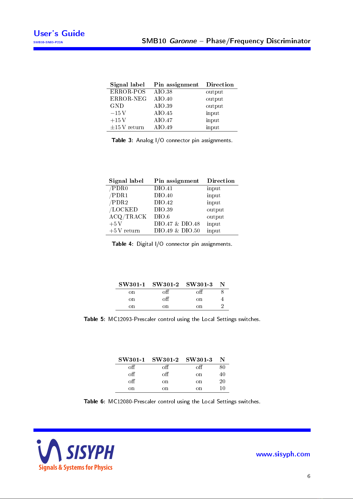
3.2.7 Pin Assignments
The pin allocations of the
Analog I/O
and
Digital I/O
stack-through headers are given in Tables 3 and
4.
3.3 Prescaler Local Settings
In addition to digital control, the divide ratio
N
of the prescaler can be set by 3 switches
SW301-A
,
SW301-B
and
SW301-C
located on the printed circuit board. Use these switches if remote control is not
required, otherwise the switches must remain in o position. The conguration depends on the integrated
circuit in use for the prescaler according Tables 5 and 6.
The digital /PDR0, /PDR1 and /PDR2 control pins
should be left open or set high
.
SISYPH
Signals & Systems for Physics
www.sisyph.com
5
User's Guide
SMB10-SN03-P22A
SMB10
Garonne
Phase/Frequency Discriminator
Signal label Pin assignment Direction
ERROR-POS AIO.38 output
ERROR-NEG AIO.40 output
GND AIO.39 output
−15 V
AIO.45 input
+15 V
AIO.47 input
±15 V
return AIO.49 input
Table 3:
Analog I/O connector pin assignments.
Signal label Pin assignment Direction
/PDR0 DIO.41 input
/PDR1 DIO.40 input
/PDR2 DIO.42 input
/LOCKED DIO.39 output
ACQ/TRACK DIO.6 output
+5 V
DIO.47 & DIO.48 input
+5 V
return DIO.49 & DIO.50 input
Table 4:
Digital I/O connector pin assignments.
SW301-1 SW301-2 SW301-3 N
on o o 8
on o on 4
on on on 2
Table 5:
MC12093-Prescaler control using the Local Settings switches.
SW301-1 SW301-2 SW301-3 N
o o o 80
o o on 40
o on on 20
on on on 10
Table 6:
MC12080-Prescaler control using the Local Settings switches.
SISYPH
Signals & Systems for Physics
www.sisyph.com
6
User's Guide
SMB10-SN03-P22A
SMB10
Garonne
Phase/Frequency Discriminator
3.4 Jumpers
There is one jumper on the SMB10's printed circuit board.
3.4.1 Acquire/Track Jumper
This normally open jumper is used to connect the
Acquire/Track Output
to the SMA91 Autolock Con-
troller module. In order the Autolock Controller to operate, a
0
-
Ω
resistor must be mounted on the the
JMP301 footprint. Can be left open if not used.
4 Circuitry
4.1 Circuit Description
The ltered output of the microwave mixer is applied to the Beat-Note input connector SMA401. The
low-pass lter RF401 provides an additional mixer-products attenuation. By default, its cut-o frequency is
set to
900 MHz
. The coupled output (
−10 dB)
of RF402 is connected to the Beat-Note monitor connector
(SMA402) while the main output is amplied (
+20 dB
) by the RF gain-block RF403. Its output level
is sucient to drive the prescaler U401 MC12093 or MC12080 depending of the desired divide ratios.
Operation at
N= 1
is obtained without any prescaler circuit. In this case, the prescaler circuit has to be
removed and a zero-ohm resistor (R403) is installed. The capacitor CX401 should be replaced with an zero-
ohm resistor if the operating frequency is below
100 MHz
. If the MC12080 is used, the resistor R404 may be
required. The prescaler divide ratio is controlled by the PDR signals coming from the digital interface.
The output of the prescaler is applied to an PECL-level translator stage (U203) whose the dierential
output pair drives the feedback pins of the LVPECL phase/frequency comparator U207. The Synchronization
input is also translated into PECL levels using the U201 driver. Its outputs are also fed to the reference
terminals of U207.
The dierential output of the phase/frequency discriminator is applied to a low-pass lter reducing the
harmonics of the Synchronization signal. The shown values are calculated for an operation at
fLO = 100 MHz
.
The Phase Error signal is given by the dierential amplier U204 whose outputs are connected to the Analog
I/O bus header through 50-ohm resistors. It is possible to boost the sensitivity of the Error signal at
low frequencies by using C212/R236 and C213/R237. These components can provide an additional gain
of
+14 dB
from DC to
4 kHz
. This features is useful to increase the overall loop-gain of the OPLL. It
also increases the SNR of the measurement. The Phase Error monitor output is obtained using another
dierential amplier U202. Its provides a tenfold copy of the Phase Error signal. In order to remove the
high-frequency harmonics, an additional lter can be implemented using the capacitors C214 and C215.
The sampled and smoothed lock-detect output of the phase/frequency comparator is applied to the
comparator U205 to provide a digital signal indicating that an locked-operation is approached.
SISYPH
Signals & Systems for Physics
www.sisyph.com
7

User's Guide
SMB10-SN03-P22A
SMB10
Garonne
Phase/Frequency Discriminator
4.2 Printed Circuit Board Legend
SISYPH
Signals & Systems for Physics
www.sisyph.com
8

User's Guide
SMB10-SN03-P22A
SMB10
Garonne
Phase/Frequency Discriminator
Document Revision History
Release Comments
SMB10-SN03-P22A rst release
Document identier
This document is identied as
SMB10-SN03-P22A
.
Notice
Information in this document is subject to change without notice. Copyright c
SISYPH, 2022. All rights
reserved.
SISYPH
Signals & Systems for Physics
www.sisyph.com
9
Other manuals for SMB10
1
Table of contents


