Sit Proflame 2 Technical manual
9.957.104 01
PROFLAME 2 BATTERY HOLDER
USE AND INSTALLATION INSTRUCTIONS
Read the instructions before use.
2
PROFLAME 2 BATTERY HOLDER USE AND INSTALLATION INSTRUCTIONS
Battery Holder
Supply voltage 6.0 V (four 1.5 V AA batteries)
Ambient temperature ratings 0 - 60 °C (32 - 140 °F)
TECHNICAL DATA
2
IMPORTANT
The Proflame 2 Battery Holder is optional part of the Proflame 2 System, which is connected
with a wire harness. With the Battery holder connected the system will consist of 3 elements:
• Proflame 2 Transmitter
• Proflame 2 Battery Holder
• Proflame 2 Integrated Fireplace Control (IFC)
Please use this Installation manual in conjunction with the Proflame 2 IFC System manual, for
complete installation instructions.
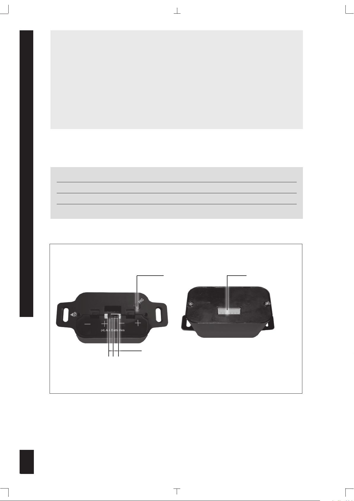
Fig. 1: Proflame 2 Battery Holder body.
The Proflame 2 Battery Holder includes: a three position switch On/Remote/Off, Transmitter
programming button (PRG) and gives the possibility, when used with the Proflame 2 system, to
mount the batteries in a single gang junction box away from the hearth appliance.
The Proflame 2 IFC Board can be powered by battery pack for back up (ATMO Systems only -refer
to Proflame 2 IFC instruction manual) in case of mains power interruption.
3 Positions Slider
6 PIN terminal
PRG Key
ON REMOTE OFF
3
PROFLAME 2 BATTERY HOLDER USE AND INSTALLATION INSTRUCTIONS
3
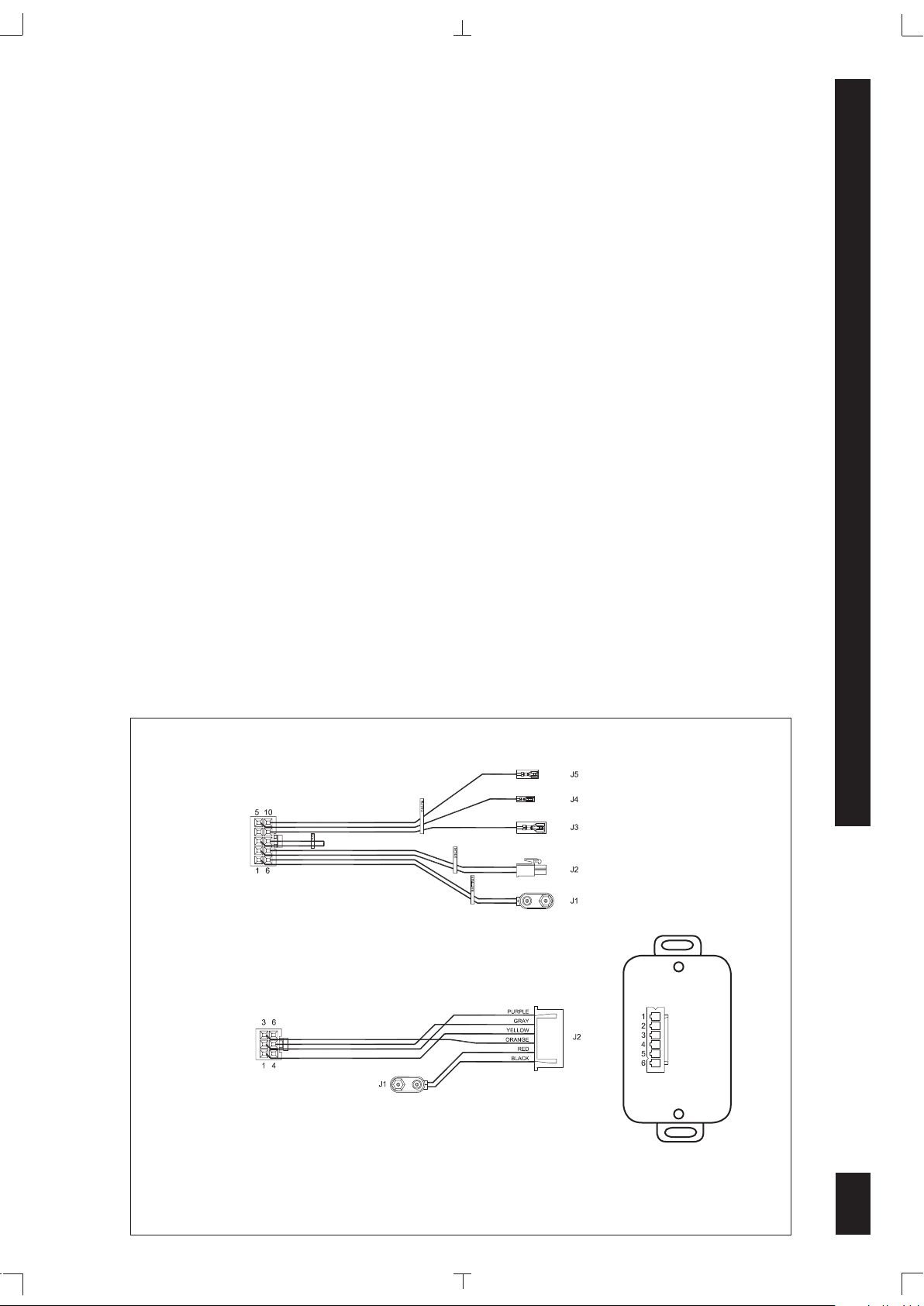
Fig. 2: Wiring diagram.
FUNCTIONS
The Proflame 2 battery holder provides backup system power during line power interruption
through the installed 4 AA type batteries.
The Proflame 2 battery holder connects directly to the Proflame 2 integrated fireplace control (IFC)
board through the 0.584.920 and 0.584.922 wire harness, see Fig.2.
The Proflame 2 battery holder has a three position slider switch for system control. The slider switch
can be set to one of three positions:
OFF position
With the slider in OFF position, the system is "OFF". No function can be selected by the transmitter.
No "beep" will be emitted from the Proflame 2 IFC when a command is sent by pressing any key on
the transmitter (for example the ON / OFF key).
ON position
With the slider in ON position, the burner flame is "ON". Only the other functions ( Fan, Lights, etc.)
can be selected by the transmitter.
Remote position
With the slider in Remote position, all the functions can be selected by the transmitter.
Programming Button (PRG)
When pushed allows a transmitter to be accepted for use by the system. See "Initializing the
System for the first time"
0.584.920
0.584.922
CONNECT TO
IFC BOARD
X8 TERMINAL
CONNECT TO
IFC BOARD
X5 TERMINAL
CONNECT TO
BATTERY
HOLDER 6 PIN
TERMINAL
CONNECT TO
0.584.920
J1 TERMINAL
CONNECT TO
0.584.922
J1 TERMINAL

4
PROFLAME 2 BATTERY HOLDER USE AND INSTALLATION INSTRUCTIONS
4
CAUTION
Property Damage Hazard.
Excessive heat can cause property damage.
The appliance can stay lit for many hours. Turn off the appliance if it is not going to be
attended for any lenght of time.
Always place the Transmitter where children can not reach it.
WARNING
Fire Hazard. Can cause severe injury or death
The Receiver causes ignition of the appliance. The appliance can turn on suddenly. Keep
away from the appliance burner when operating the remote system or activating manual
bypass of the remote system.
LOW BATTERY POWER DETECTION
The life span of the Proflame 2 IFC batteries depends on various factors: quality of the batteries
used, the number of ignitions of the appliance, the number of changes to the room thermostat set
point, etc.
When the Proflame 2 IFC batteries are low, two (2) “beeps” will be emitted from the Proflame 2 IFC
every time it receives a command from the Transmitter. This is an alert for a low battery condition
for the Proflame 2 IFC. When the batteries are replaced one (1) “beep” will be emitted from the
Proflame 2 IFC when a command is sent by pressing any key on the transmitter (for example the
ON / OFF key), see "Initialization of The System".
Preliminary check of the Battery Holder
Operations to be done, before switching on the Remote Control:
•
Check that the wiring harness connections are made correctly between the Proflame 2 Battery
holder and the Proflame 2 Integrated Fireplace Control (IFC). If 0.584.920 and 0.584.922 wire
harness are used, connect 0.584.920 J1 terminal to 0.584.922 J1 terminal, see Fig. 2.
Initializing the Transmitter/Receiver link System for the first time
Install the 4 AA batteries into the Proflame 2 Battery holder battery bay. Note the polarity of the
battery and insert into the battery bay as indicated on the cover (+/-). Place the 3 position slider
switch in the “Remote” position. (Fig. 1) Insert the end of a paper clip or similar object into the
hole marked "PRG" on the Receiver front cover. (fig 1) The Receiver will “beep” three (3) times
to indicate that it is ready to synchronize with a Transmitter. Install the 3 AAA type batteries in
the Transmitter battery bay, located on the base of the Transmitter and push the On button. The
Receiver will “beep” four times to indicate the Transmitter’s command is accepted and set to the
particular code of that Transmitter. The system is now initialized.
Table of contents


