Site Buddy PROFESSIONAL SERIES 30TP User manual
OWNER’S MANUAL
DIESEL POWERED TRASH PUMP
IMPORTANT ─Please make certain that persons who are to use this equipment thoroughly
read and understand this user’s manual prior to operation

PREFACE
Thank you for purchasing our products. We appreciate your business. The following manual
is only a guide to assist you and is not a complete of comprehensive manual of all aspects of
your water pump unit. Some of the illustrations and photos will differ slightly then your
model and only serve as an illustration. The equipment you have purchased is a complex
piece of machinery. We recommend that that you consult with a dealer if you have doubts or
concerns as to your experience or ability to properly maintain or repair your equipment. You
will save time and the inconvenience of having to go back to the store if you choose to write
or call us concerning missing parts, service questions, operating advice, and/or assembly
questions. Our diesel powered water pumps have some of the following features:
●Lightweight construction
●Hard working four-stroke diesel internal combustion engine
●Large fuel tank
●High quality mechanical seals
●Self-priming structure
The air-cooled diesel semi trash pumps are self-priming single-stage centrifugal water pumps.
The bodies of the water pumps are constructed of high quality die-cast aluminum alloy. The
internal rotating rings arc constructed of ceramics and the stationary rings are constructed of
graphite. The water pumps are widely used in fieldwork and on construction sites. Our water
pumps provide a portable mobile solution in pumping liquids from one place to another.
This manual will explain how to operate and service your semi-trash pump unit.

TABLE OF CONTENTS
Page number
OVERVIEW OR VARTOUS MODELS OF WATER PUMPS ………………….…...….….1
TECHNICAL SPECIFICATIONS ……………………………………………………………2
WATER PUMP SAFETY PRECAUTIONS …………… ……………………….……4
KNOWING YOUR SEMI-TRASH PUMP …………………………………………………..5
PRE-OPERATTON PREPARATION ………………………………………………………..6
STARTING THE ENGINE ………………………………………………………………….10
OPERATION ………………………………………………………………………………...14
STOPPING THE ENGINE …………………………………………………………………..15
MAINTENANCE …………………………………………………………………………...16
IRAN SPORTING AND STORAGE …………………………………………………….….20
TROUBLESHOOTING……………………………………………………………………...21
PUMP DIAGRAMS AND PARTS LISTINGS ……………………………………………..23
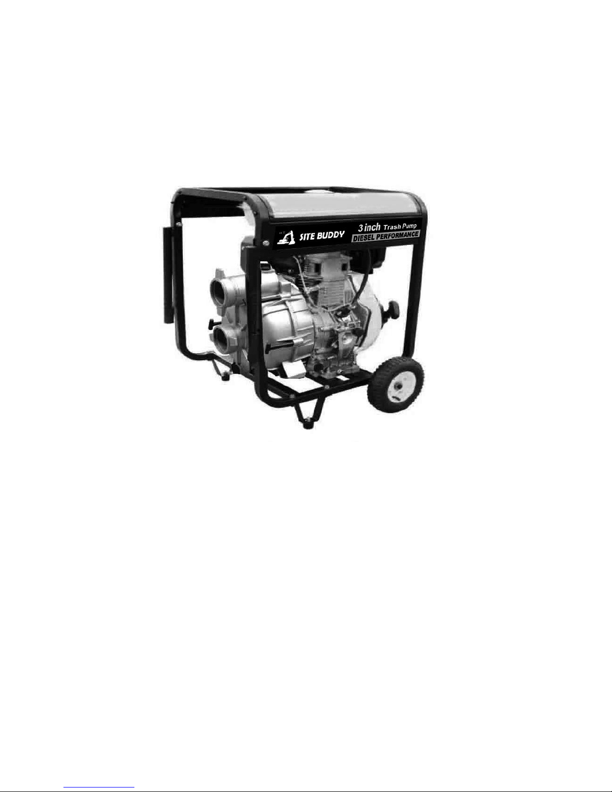
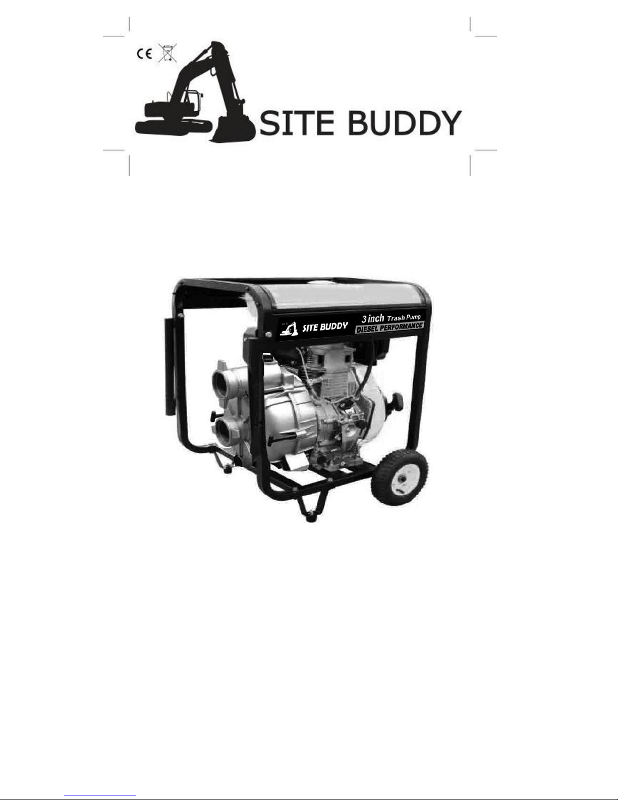
OVERVIEW OF VARIOUS MODELS OF WATER PUMPS
Figure 1.Overall view of the diesel water pump unit
PROFESSIONAL SERIES MODEL

TECHNICAL SPECIFICATIONS
Table 1. Specifications in Metric units
Model No. 30TP
Suction port diameter(mm) 80
Discharge port diameter(mm) 80
Suction height(m) 7
Pump lift (m) 25
Pump
Displacement (m3) 55
Engine TP178E
Speed(rpm) 3600
Displacement(cc) 296
Max.Output(kw) 4.0
Cooling system Forced air cooling by flywheel
Ignition Direct fuel injection
Engine
Shaft rotation Clockwise from flywheel end
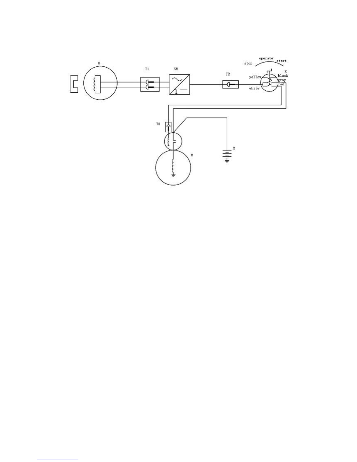
Wiring Diagram (optional for electric start models only)
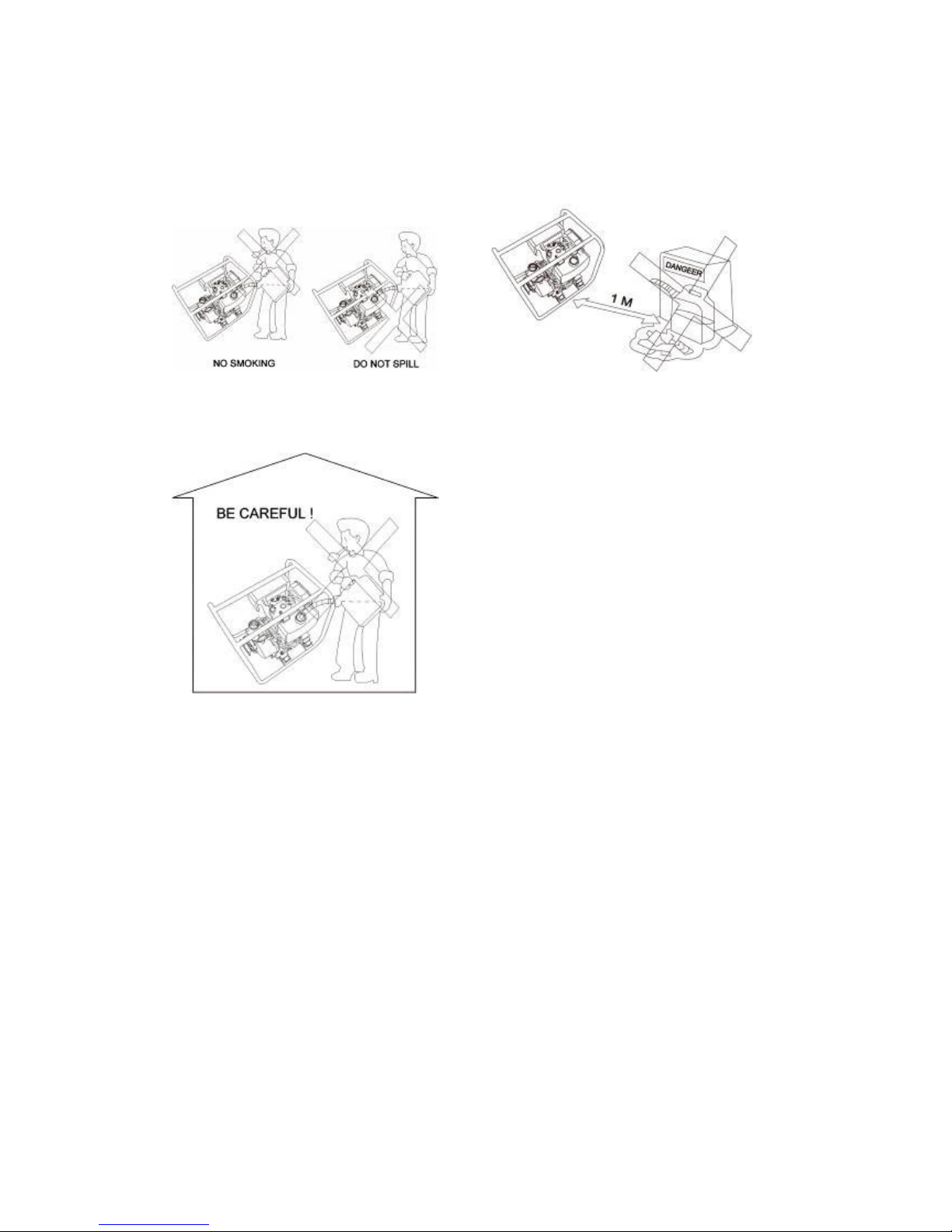
SEMI-TRASH PUMP SAFETY PRECAUTIONS
●Do not smoke or allow flames or sparks to
get near fuel. Always refuel your engine in a
well-ventilated place. Do not overfill the tank
and always close the filler cap securely.
●Never run the pump indoors as the engine
emits poisonous carbon monoxide.
●Do not touch the muffler during or just after
operation, as the engine and muffler get hot
Always let the engine fully cool before touching
and storing the pump indoors.
●Always keep the pump at least 1 meter (3
feet) away from buildings and other equipment
during operation. Do not place flammable
objects or liquids close to the pump.
●Before operating your semi-trash pump,
please check your local laws and regulations
before operating your pump. It is illegal in some
areas to operate an engine without a spark
arrester.
●Know all the pumps controls and know how
to stop the pump quickly in the event of an
emergency. Do not let anyone without proper
instructions operate the pump.
●Always keep children and pets away from
the pump.
●Do not pump flammable or corrosive liquids
such as gasoline or acid. In order to prolong the
life of your pump, avoid pumping corrosive
1iquds such as sea-water, chemical solutions,
used oil, or acidic liquids.
●Always operate your pump on a level surface.
If the pump is tilted, fuel may spill and rapid
wear might occur as a result of inadequate
lubrication.

KNOWING YOUR WATER PUMP
STANDARD MODEL
Fuel cap
Muffler
Cleaner
Recoil Starter
Oil drain plug
Oil
D
epth
Gauge
a
nd Inlet
P
ort
Suctio
n Port
Priming water filler cap
Outlet
PRE-OPERATION PREPARATION
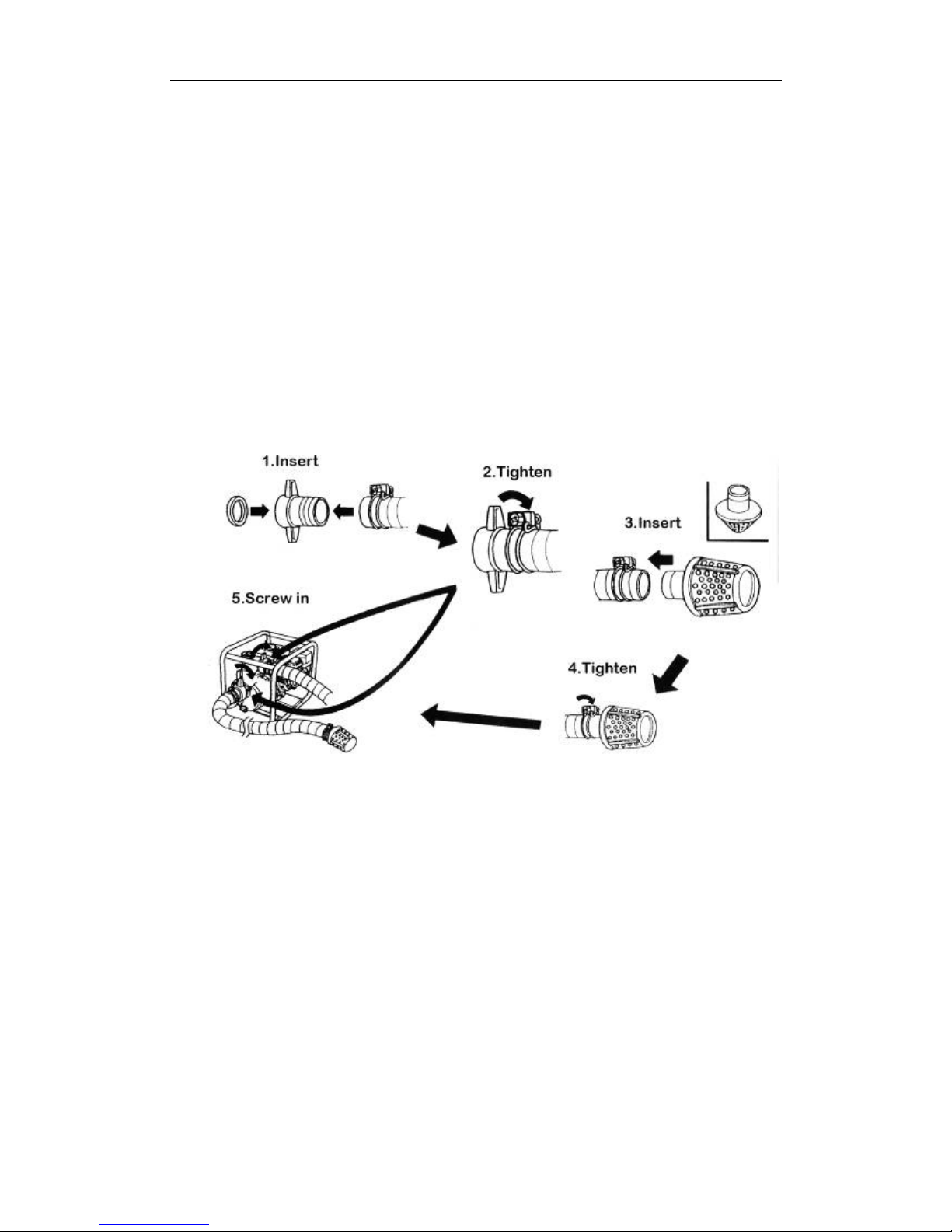
Suction Hose
The first step in preparing the pump for operation is to install the suction hose. For the suction hose,
use a reinforced-wall or wire braided hose to prevent suction collapse. A short hose is recommended
over a long hose. The pumps have standard National Pipe Threads on them; therefore, any standard
hose set will fit with the pump. If your hoses arc metric threads or any other standard, please give our
company a call and we may carry a full line of adapters or provide you with a possible solution.
NOTE: Always install the provided strainer on the end of the suction hose before pumping. If gravel or
debris enters the pump, the impeller can he seriously damaged.
Shown below is the pump hose utilizing a barbed connection and hose clamp. If you already
have specialized hose, disregard the following diagram. When using the barbed connection
setup, make sure to use a hose clamp to properly secure the hose to the barb connector.
Discharge hose
The second step is to install the discharge hose. The discharge hose can be fabric, just make
sure to use a hose clamp to secure the hose to the barb. This will prevent the hose from
disconnecting under high pressure.
Note: A short and large-diameter hose is preferred over any other. A short and large diameter
will provide lower fluid friction and improve efficiency.
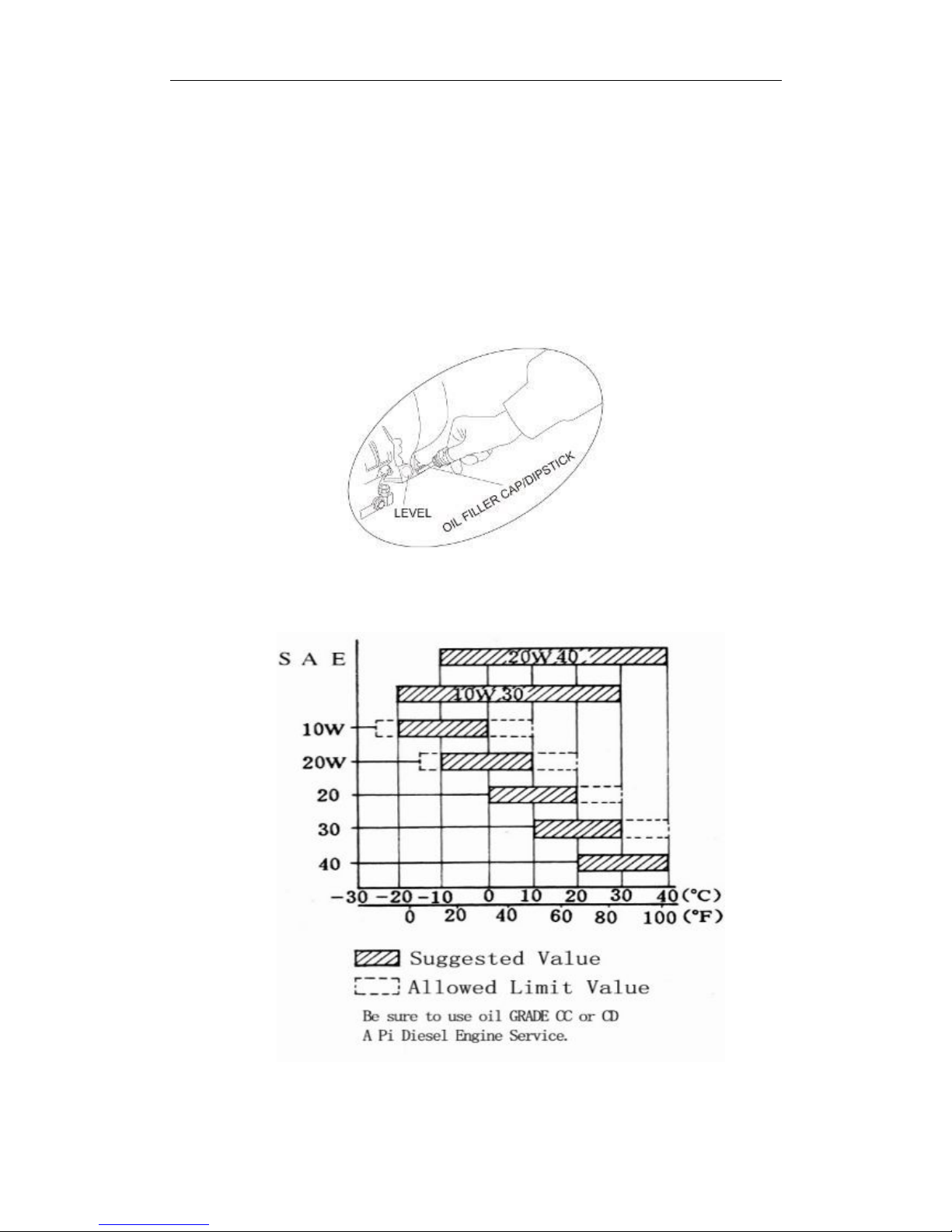
Engine oil
Engine oil is an important factor in determining the performance and life of your engine. Always
make sure the oil level is within the upper and lower limits specified on the oil dipstick. Make
sure to check the engine oil on a level surface or incorrect readings will result.
●To check the engine oil, first, remove the oil dipstick by turning counterclockwise.
●
Wipe the dipstick clean and insert the dipstick back into the oil filler neck. Do not screw it in.
Please refer to Fig 2-1.
●If the level is low, fill engine oil to the top of the oil filler neck with the recommended oil
below.
Fig 2-1. Illustration of checking the engine oil
Below is a table of recommended oil grades for the engine in various weather conditions.
Please use the proper oil according to the Table 2-1.
Table 2-1. Ambient temperature versus oil grades
Note: For diesel engines, we highly recommend the use of 15W-40 engine oil. Some other grades
are comparable, but 15W-40 is the preferred oil grade.

Fuel
Remove the fuel cap and fill the fuel tank with diesel fuel. The preferred fuel for
diesel engines is diesel number 2, which can be easily obtained from a gas station. Do not
use other fuels until consulting with your local dealer or our company.
Do not smoke or allow flames or sparks to get near fuel. Always refuel your engine in a
well-ventilated place. Do not overfill the tank and always close the filler cap securely.
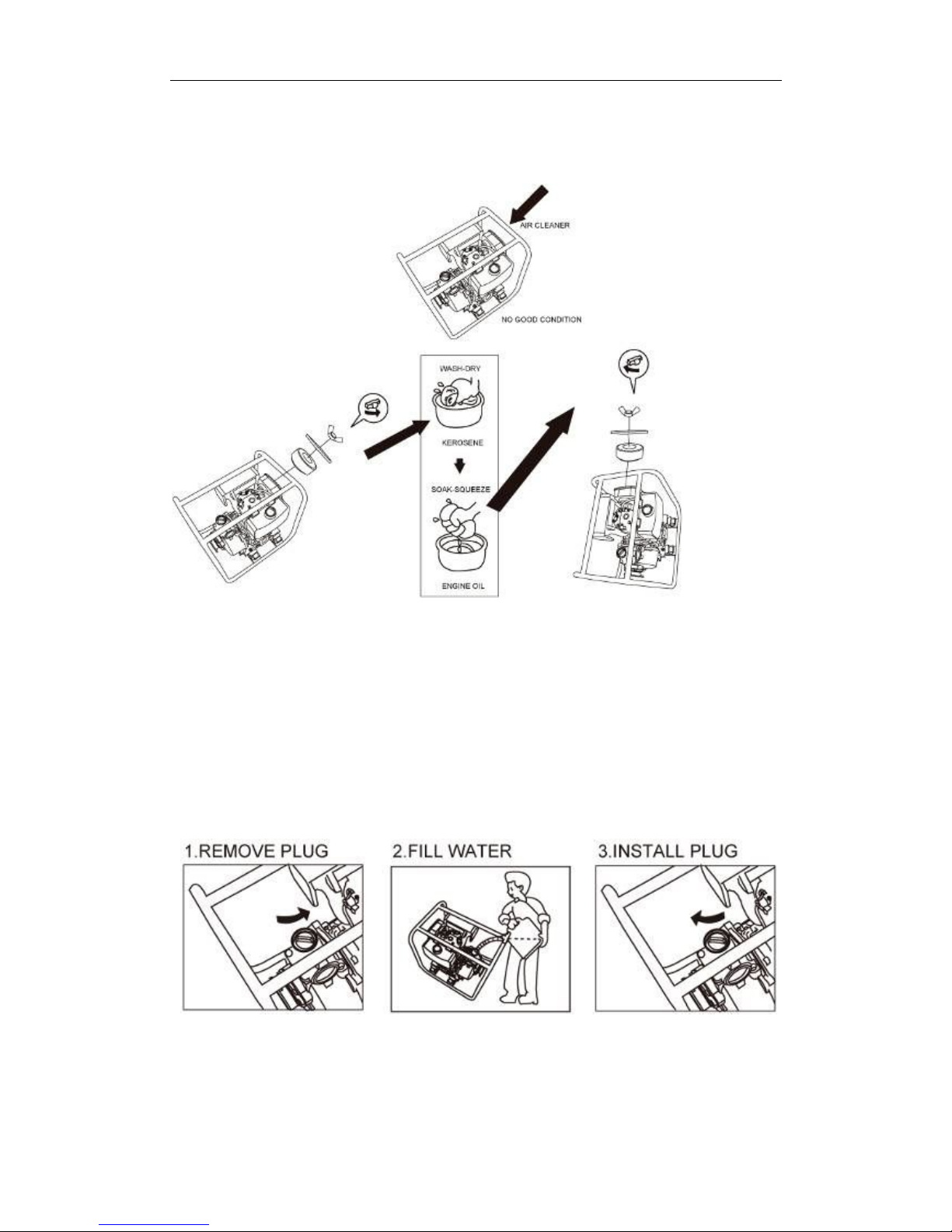
Air Cleaner
Before starting your water pump, remove your air cleaner cover and verify that the air filter is
clean and free of debris. Clean the air filter if necessary.
Priming water
The pump chamber should be completely filled before operating.
Note: Never operate the pump without priming water or the pump will overheat. Prolonged
operation of the pump under these dry conditions will damage and destroy the seal.
Follow these guidelines to fill the pump with priming water.
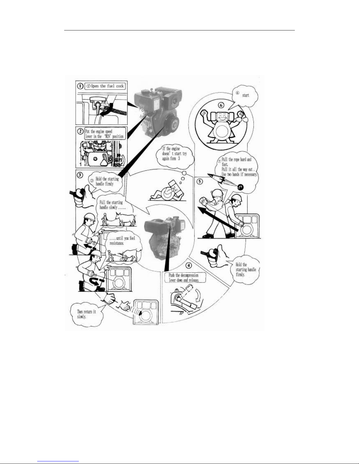
STARTING THE ENGINE
Recoil Starting
Note: When the engine is running, do not pull the recoil handle, otherwise the engine
may be damaged.

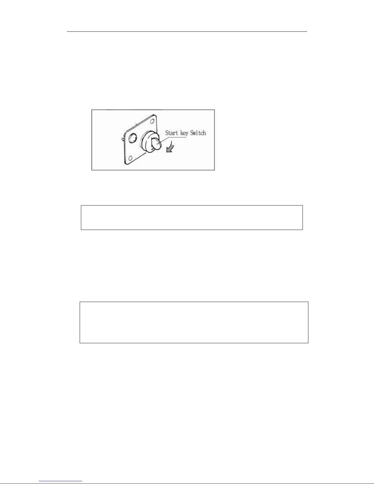
Diesel Engine with Electric Starter System
Starting
The preparation of the diesel engine for the electric starting system is the same as the manual
recoil type.
a. Open the fuel cock.
h. Set the speed governor lever to the start position.
c. Turn the start switch clockwise to the “Start”position.
d. If the engine is started, immediately remove your hand away from the key switch.
e. If the engine does not start after 10 seconds, wait a while about 15 second before trying
to start the engine again.
(1) Battery
a. Always check the liquid level of the battery every month, if the level is lower than the low
limit mark, refill the battery with distilled water till you reach the upper limit mark.
If the liquid level in the battery is to low, the electric stater will not function to its best
potential. Always keep the level of the liquid in the battery between the upper and lower
limits. If there is too much liquid, the liquid will splash onto other nearby parts there by
ruining the battery.
If you run the starter motor to long, the voltage of the accumulator will drop and the
motor may be damaged. Keep the key switch in the “ON” position.

Cold starting
If the engine is difficult to start in winter, take off the rubber seal plug and put 2cc of machine oil
into the hole.
Notice: Engines supplied to the Torrid Zone will not contain the rubber plug. A solid plug is
provided instead.
Warning:
Never use flammable liquids as fuel, such as gasoline etc. Also, never take away the air
cleaner for easy starting of the engine, doing so may cause explosions from the intake gases.
Never take the oil plug unless you’re planning on filling the oil. If the plug is not in place,
rain, dust, and other impurities may be sucked into the engine causing serious damage to the
engine parts.

OPERATION
Operating condition
The water pumps operating range should be based upon the NPSH (net positive suction head).
A more precise definition of available NPSH is “the difference between the total suction head
and the vapor pressure of the liquid, in feet of liquid, at the suction flange”. We can measure
the total suction head of the pump and we can find vapor pressure from the liquid temperature.
The difference between these two values is the available NPSH. The following equation is the
mathematical expression of the definition for available NPSH:
hsv = has - hvpa where:
hsv = available net positive suction head, in feel of liquid
hsa = total suction head, in feet of liquid, absolute
hspa = vapor pressure of liquid at suction nozzle, in feet of liquid, absolute
The approximation will be based at an altitude less than 250 meters or 820 feet. Subtracting
10 meters or 32.8 feet from the net positive suction head can approximate the suction head of
the pump. When increasing the altitude of operation, the atmosphere should be decreased as
well as the suction head of the pump. The amount of decrease can be estimated by subtracting
10 meters from the local atmosphere value. If you are using sour pump at high altitudes and
having difficulty obtaining NPSH values, please consult your local power equipment dealer.
It is better to use a straight and short pipeline when operating the water pump. A short and
straight pipeline will minimize the frictional loses in the pipeline. The pipeline should be
fixed to something to avoid vibrations. Before operating the pump, you must check the
connections between the pump and pipelines to verify that everything is installed properly and
that there are no leaks of any kinds.
The filter net should be kept at a certain distance between the river surface, river bottom, and
riverbank. The net must also be submerged at least 0.3 meters or 1 foot below the water
surface to avoid sucking air into the pipeline. The net must also be 0.2 meters or 0.7 feet
above the river bottom or riverbank to avoid sucking stones or weeds into the pipeline.
If the gap between the impeller and flow guidance surface is over 1 mm, an adjustment shim
can be added on the shaft shoulder to reduce the gap. This will permit continuous use of the
water pump. Please refer to figure 2-2 for a diagram of the water pump and a listing of the
components.

STOPPING THE ENGINE
First, bring down the speed of the engine by using the speed governor. Let it run for 3 minutes
at no load before stopping it.
Then stop the engine.
Sudden stops to the engine will cause abnormal temperature
increases in the block of the engine. Decrease the load
gradually when stopping the engine. Also, never stop the
engine with the decompression lever.
Set the fuel cock at “S” (stop position)
If the engine comes with an electric starter, turn the starting switch to the “Off”position.
Pull the recoil handle slowly until pressure is felt by your hand, this means the piston is on the
compression stroke; where the intake and exhaust valves arc closed and then let the handle
recoil back into the engine. This natural position will prevent rust from occurring when the
engine is being stored for long periods of time. Perform these steps only when the engine is
off; doing so otherwise will damage the engine.

MAINTENANCE
Oil check
During operation, it is a good idea to check the oil every morning to ensure the engine has
sufficient oil.
CHECK OIL EVERY MORNIING
Oil change
Engine oil is a critical factor in determining the life of your engine. Change the engine oil on
time. Change the engine oil more frequently if the engine is used in dusty areas.
Changing the oil while the engine is still warm will yield best results for the engine. When the
oil is still warm, you get rapid and complete draining of the oil.
Oil change procedures
● Remove the oil filler cap and drain plug to drain the oil
● Install the drain plug, and tighten it securely.
● Refill with the recommended oil and check the oil level.
● Install the oil filler cap.

Note: Do not touch motor oil for long periods of time. Used motor oil can cause skin cancer if
it comes in contact with the skin for prolonged periods of time. Getting cancer from used
motor oil is unlikely unless you handle used motor oil on a daily basis. To be safe always
wash your hands thoroughly with soap and water as soon as possible after handling used oil.
Below a maintenance schedule table is provided.
Time
Item Daily
After 20 hours
or 1 month
100 Hours or Every
3 month
500 Hours or
Every 6 month
1000 Hours or
Every year
Check and tighten the nut and screw ○
Check and fill machine oil ○
Change machine oil ○
(First time)
○
(Second time and later)
Clean and change oil filter ○●
(Change)
Check oil-leakage ○
Change the core of air filter Cycle of check and main-tenance will
be shortened at dusty place. ○
Clean fuel tank Every month
Clean or chane fuel filter ○
(Clean)
○
(Change)
Check nozzle ●
Check injection pump ●
Check pipeline of fuel
○
(Change if
necessary)
Adjust value clearance of inlet and
exhaust ●
(First time)
●
Grind value holder of inlet and exhaust ●
Change piston ring ●
Check accumulator liquid each month
Clean the core of air filter
○
(Clean)
Every month or 50 hours
Air filter service
A dirty or clogged air filter will prevent air from flowing freely into the carburetor assembly.
Always keep the air filter clean or replace if necessary. Also, if the air filter is dirty or
clogged, the performance of the engine goes down. If operating the engine in a dusty area,
service the air filter more frequently as dust particles will clog the filter at a faster rate. Never
run the engine without an air filter, dust particles may get into the intake system and damage
the engine. Rapid engine wear will occur if the engine is run without the air filter.
Table of contents
Popular Water Pump manuals by other brands


Grundfos
Grundfos seg autoadapt Installation and operating instructions

Pfeiffer Vacuum
Pfeiffer Vacuum Pascal Series Maintenance Instruction

Alcatel Vacuum Technology
Alcatel Vacuum Technology ATP 100 Service manual & troubleshooting guide

T.I.P.
T.I.P. WPZ 450 R operating instructions

Trotec
Trotec TDP 370 E Original instructions

Pentair
Pentair Myers AWS-1 Installation and service manual

PSG Dover
PSG Dover All-Flo S050 Installation operation & maintenance

Profi-pumpe
Profi-pumpe INVERT-TECH 2 operating instructions

Pentair
Pentair VERSAILLES 160/8 instruction manual

Burcam
Burcam 506518SS installation instructions

Varian
Varian Turbo-V 1000HT instruction manual

IMER
IMER PRESTIGE Operating, maintenance, spare parts manual