Sitepower SP950 Technical manual

1
OPERATION INSTRUCTION
SP950
Walk-Behind Concrete Power Trowel
Before using the SitePower™ SP950 Walk-Behind Concrete Power
Trowel, please read this manual carefully.

2
Table of Contents
1. Foreword………………………………………………………………………………… 3
2. Safety Information……………………………………………………………………… 3
2.1. Laws Pertaining to SparkArresters……………………….………………… 4
2.2. Operating Safely……………………………………….……………………… 4
2.3. Operator Safely while using Internal Combustion Engine……..………… 5
2.4. Service Safety………………….……………………………………………… 6
3. Technical Data…………………………………………………………………………… 7
3.1. Engine Data………………………………………………….………………… 7
3.2. Machine Data…...................…………………………………………………. 7
4. Operation…………………………………………………………………………………. 8
4.1. Application…………….……………………………………………………….. 8
4.2. New Machine Setup…………………………………………..……………… 8
4.3. Recommended Fuel …………………………………………..…………….. 8
4.4. Installing Blades …………………………………..…………………………. 9
4.5. Installing andAdjusting Handles ……………………………….…………… 6
4.6. Controls…………………………………………….……………..………….. 11
4.7. Run/Stop Switch……………………………………………………………... 11
4.8. Before Starting……………………………………………………………….. 11
4.9. To Start………………………………………………………………………… 11
4.10. To Stop………………………………………………………………………… 12
4.11. Operaton………………………………………………………………………. 12
5. Maintenance………………………………………………….…………..………….. 13
5.1. Periodic Maintenance Schedule…………………….………………….…. 13
5.2. Cleaning Plate……………………………………………….……………… 14
5.3. Drive Belt……………………….……………………………………………. 14
5.4. Exciter Lubrication……………….…………………………………………. 14
5.5. Spark Plug………………….…………………….………………………….. 15
5.6. Engine Oil……………………………………………………………….……. 16
5.7. Air Cleaner……………………………………….…………………………… 17
5.8. Cleaning Sediment Cup……………………………………….…………….. 18
5.9. CarburetorAdjustment…………………………………….………………... 18
5.10. Storage……………………………………………………………………….. 19
5.11. Lifting Machine………………………………………………………………. 19
5.12. Transporting Machine……………………………………………………….. 20

3
1. Foreword
This manual provides information and procedures to safely operate and maintain this
SitePower model. For your own safety and protection from injury, carefully read,
understand and observe the safety instructions described in this manual.
Keep this manual or a copy of it with the machine. If you lose this manual or need an
additional copy, please contact SitePower. This machine is built with user safety in mind;
however, it can present hazards if improperly operated and serviced. Follow operating
instructions carefully! If you have questions about operating or servicing this equipment,
please contact SitePower.
The information contained in this manual was based on machines in production at the
time of publication. SitePower reserves the right to change any portion of this information
without notice.
No part of this publication may be reproduced in any form or by any means, electronic or
mechanical, including photocopying, without express written permission from SitePower.
Any type of reproduction or distribution not authorized by SitePower represents an
infringement of valid copyrights and will be prosecuted. We expressly reserve the right to
make technical modifications, even without due notice, which aim at improving our
machines or their safety standards.
2. Safety Information
This manual contains DANGER, WARNING, CAUTION, and NOTE callouts which must
be followed to reduce the possibility of personal injury, damage to the equipment, or
improper service.
This is the safety alert symbol. It is used to alert you to potential personal
injury hazards. Obey all safety messages that follow this symbol to avoid
possible injury or death.
DANGER indicates an imminently hazardous situation which, if not
avoided, will result in death or serious injury.
WARNING indicates a potentially hazardous situation which, if not avoided,
could result in death or serious injury.
CAUTION indicates a potentially hazardous situation which, if not
avoided, may result in minor or moderate injury.
DANGER
WARNING
CAUTION

4
CAUTION: Used without the safety alert symbol, CAUTION indicates a potentially
hazardous situation which, if not avoided, may result in property damage.
2.1 Laws Pertaining to Spark Arresters
Notice: State Health Safety Codes and Public Resources Codes specify that in certain
locations spark arresters be used on internal combustion engines that use
hydrocarbon fuels. A spark arrester is a device designed to prevent accidental
discharge of sparks or flames from the engine exhaust. Spark arresters are qualified
and rated by the United States Forest Service for this purpose.
In order to comply with local laws regarding spark arresters, consult the engine
distributor or the local Health and Safety Administrator.
2.2 Operating Safely
2.2.1 NEVER allow anyone to operate this equipment without proper
training. People operating this equipment must be familiar with the risks and
hazards associated with it.
2.2.2 NEVER touch the engine or muffler while the engine is on or
immediately after it has been turned off. These areas get hot and may cause burns.
2.2.3 NEVER use accessories or attachments that are not recommended by
SitePower. Damage to equipment and injury to the user may result.
2.2.4 NEVER operate the machine with the beltguard missing. Exposed drive
belt and pulleys create potentially dangerous hazards that can cause serious injuries.
2.2.5 NEVER leave machine running unattended.
2.2.6 ALWAYS be sure operator is familiar with proper safety precautions and
operation techniques before using machine.
Familiarity and proper training are required for the safe
operation of equipment! Equipment operated improperly or by
untrained personnel can be dangerous! Read the operating
instructions contained in both this manual and the engine
manual and familiarize yourself with the location and proper use
of all controls. Inexperienced operators should receive instruction
from someone familiar with the equipment before being allowed
to operate the machine.

5
2.2.7 ALWAYS wear protective clothing appropriate to the job site when
operating equipment.
2.2.8 ALWAYS wear hearing protection when operating equipment.
2.2.9 ALWAYS close fuel valve on engines equipped with one when machine
is not being operated.
2.2.10 ALWAYS store equipment properly when it is not being used. Equipment
should be stored in a clean, dry location out of the reach of children.
2.2.11 ALWAYS operate machine with all safety devices and guards in place and in
working order. DO NOT modify or disable safety devices. DO NOT operate machine
if any safety devices or guards are missing or inoperative.
2.2.12 ALWAYS read, understand, and follow procedures in Operator's Manual
before attempting to operate equipment.
2.3Operating Safely while using Internal Combustion Engines
2.3.1 DO NOT run machine indoors or in an enclosed area, such as a deep trench,
unless there is adequate ventilation (exhaust fans or hoses) is provided.
Exhaust gas from the engine contains poisonous carbon monoxide gas.
Exposure to carbon monoxide can cause loss of consciousness and may lead to
death.
2.3.2 DO NOT smoke while operating machine.
2.3.3 DO NOT smoke when refueling engine.
2.3.4 DO NOT refuel hot or running engine.
2.3.5 DO NOT refuel engine near open flame.
2.3.6 DO NOT spill fuel when refueling engine.
2.3.7 DO NOT run engine near open flames.
2.3.8 ALWAYS refill fuel tank in well-ventilated area.
Internal combustion engines present special hazards during
operation and fueling. Read and follow warning instructions in the
engine owner's manual and safety guidelines, outlined below.
Failure to follow warnings and DANGER safety guidelines could
result in severe injury or death.

6
2.3.9 ALWAYS replace fuel tank cap after refueling.
2.3.10 Always check fuel lines and fuel tank for leaks and cracks before starting
engine. Do not run machine if fuel leaks are present or fuel lines are loose.
2.4Safety Service
2.4.1 DO NOT attempt to clean or service the machine while it is running.
Rotating parts can cause severe injury.
2.4.2 DO NOT crank a flooded engine with the spark plug removed on gasoline-
powered engines. Fuel trapped in the cylinder will squirt out the spark plug opening.
2.4.3 DO NOT test for spark on gasoline-powered engines, if engine is flooded or
the smell of gasoline is present. A stray spark could ignite fumes.
2.4.4 DO NOT use gasoline or other types of fuels or flammable solvents to clean
parts, especially in enclosed areas. Fumes from fuels and solvents can become
explosive.
2.4.5 ALWAYS keep area around muffler free of debris such as leaves, paper,
cartons, etc. A hot muffler could ignite them, starting a fire.
2.4.6 ALWAYS replace worn or damaged components with spare parts designed
and recommended by SitePower.
2.4.7 ALWAYS disconnect spark plug on machines equipped with gasoline engines,
before servicing, to avoid accidental start-up.
2.4.8 ALWAYS keep machine clean and labels legible. Replace all missing and hard-
to-read labels. Labels provide important operating instructions and warn of dangers and
hazards.
Poorly maintained equipment can become a safety hazard!
In order for the equipment to operate safely and properly over a
long period of time, periodic maintenance and occasional repairs
are necessary.

7
3. Technical Data
3.1 Engine Data
3.2 Machine Data
Gear Box Lubrication type/ml (oz.)
Mobil SHC634
Approx. 1330 (45)
Operating Weight
kg
84
Trowel Diameter mm
1000
Speed Range rpm
60-127
Pitch Range
degrees
0 – 15
Engine
Engine Make
BRIGGS&STRATTON
Engine Model
BS1062
Rated Power
kW (Hp)
4.1 (5.5)
Engine Speed - full
Engine Speed - idle
Clutch Engagement
rpm
rpm
rpm
3600 ± 100
1600 ± 100
2100
Spark Plug
type
NGK BPR 6ES
Electrode Gap
mm (in)
0.7-0.8 (0.028-0.031)
Air Cleaner
type
Dual Element
Engine Lubrication
oil grade service
class
SAE 10W30 SG or SF
Engine Oil Capacity
ml (oz.)
600 (20)
Fuel type
Regular unleaded
gasoline
Fuel Tank Capactity
l (qts.)
3.7 (3.9)
Valve Clearance
(cold)
mm (in.) Inlet: 0.15 (0.006)
Outlet: 0.20 (0.008)

8
4. Operation
4.1 Application
This trowel is a modern, high production machine intended for floating and
finishing freshly poured concrete slabs. The machine's good balance, adjustable
handle, and easily reached controls add to operator comfort and productivity. An
automatic Run/Stop Switch, or a combination of an automatic Run/Stop Switch
and an Operator Present Lever, provide added operator safety. Finishing rates will
depend on operator skill and job conditions.
DO NOT use this machine for any application other than troweling concrete.
4.2 New Machine Set-up
Trowels are shipped from the factory with the handles and blades removed. Follow
instructions on Installing Blades and Installing and Adjusting Handles when setting
up new machines or when installing new handles and blades.
Note: Steering handles come in two styles: a bicycle style grip or a wing grip.
Assembly procedures are identical for both styles.
4.3 Recommended Fuel
The engine requires regular grade unleaded gasoline. Use only fresh, clean
gasoline. Gasoline containing water or dirt will damage fuel system. Consult
engine owner's manual for complete fuel specifications.
4.4 Installing Blades
There are four types of blades available for the trowels. Float pans are large "pizza pan"
style blades, which hook on over finish or combination blades and are available for the
30" and 36" machines only. Float blades are available for all machines and clip on over
finish or combination blades. Both are used in the earliest stages of work, and are not
pitched.
Finish blades, which are supplied with the machine, are used in the final stages of
working, and are progressively pitched to burnish the concrete.
Combination blades can be used throughout the concrete working process. They are
used in place of float blades or pans and finish blades.
Note: Trowel blades must NOT be interchanged, i.e., do NOT put larger diameter
blades on a smaller diameter trowel.

9
4.4.1 New machines are supplied with finish blades as standard equipment. Finish
blades are flat on both edges and can be installed in either direction.
When installing combination blades, orient blades as shown (a). This positions the
raised edges of the blade correctly for the clockwise rotation of the machine.
4.4.2 Secure blades to trowel arms with 1½" screws (b). Dip threads of screws in
grease prior to installation. This will prevent concrete from cementing the screws in
place and will make removal of the blades easier later on.
4.4.3 Plug the remaining threaded holes in the blade brace with plastic plugs (c) to
prevent them from filling with concrete. Do not lift the trowel overhead with a float pan
attached, as the pan could fall off and strike personnel working in the vicinity.
4.5 Installing and Adjusting Handles
On new machines the pipe handle comes assembled with the pitch control (Twist or
Pro-Shift®) (j) and stop switch (n).
To install the pipe handle assembly:
4.5.1 Pull the pitch control cable (d) from bottom end of the tube and remove the nuts
from the cable.
4.5.2 Thread the cable through the handle base (a) and over the pulley (c) as shown.
4.5.3 Attach the pipe handle to the handle base with two M8x16 screws (b). Secure the
screws using Loctite 243 or an equivalent medium-strength thread-locking compound.
Torque the screws to 22 Nm (16 ft.lbs.).
4.5.4 Push the Pro-Shift® handle all the way forward (away from the operator) OR turn
the twist pitch control handle counterclockwise as far as possible. Connect the cable to
the fork (e) as shown and adjust the cable nuts (f) so the cable is snug and the trowel
blades lay flat (0° pitch).
Steering Handle:
4.5.1 Install the steering handle (g) to the machine as shown. Secure the shoulder bolt
(k) using Loctite 243, or equivalent.
4.5.2 Position the throttle lever (h) on the handle and fasten it in place.
4.5.3 On machines equipped with an operator present lever, mount the lever (p) as
shown. When installing, be sure that the tabs on the lever dig through the paint and into
the metal of the handle. This will insure a good electrical ground. Test the function of the
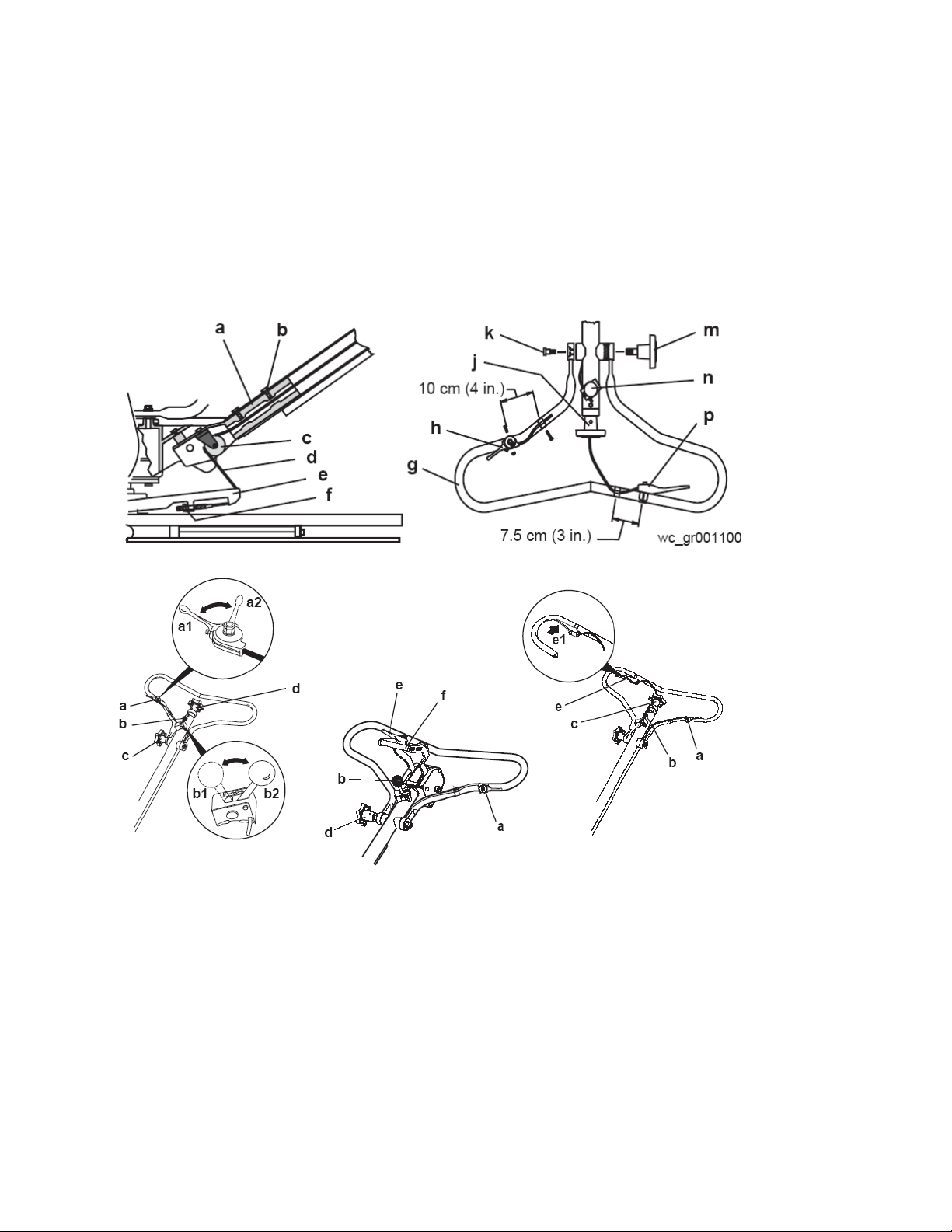
10
lever prior to using the trowel by starting the trowel and then disengaging the lever— the
trowel should stop promptly. See To Start.
4.5.4 Position the handle by loosening the knob (m) and adjusting the handle up or
down to suit the operator. Tighten the knob to secure the handle in position.
wc_gr001100 7.5 cm (3 in.)
10 cm (4 in.)
a

11
4.6 Controls
Ref. Description Ref. Description
a Throttle lever d Handle adjustment
b Run/Stop switch e Operator present lever
c Twist pitch control f Pro-Shift® pitch control
4.7 Run/Stop Switch
The Run/Stop Switch (b) is located on the pipe handle. When the switch is placed in the
“I” (run) position (b1), the engine may be started and the trowel operated. When the
switch is placed in the “O” (stop) position (b2), the engine will not run and the trowel
stops.
To prevent uncontrolled spinning of the trowel, the Run/Stop Switch is also designed to
automatically close under certain conditions and shut off the engine. For example, if the
operator loses his/her grip on the trowel, the centrifugal force created by the spinning
machine will pull the switch to the “O” position, stopping the trowel.
4.8 Before Starting
4.8.1 Read and understand safety and operating instructions at beginning of this
manual.
4.8.2 Check:
Oil level in engine.
Fuel level.
Condition of air cleaner.
Tightness of external fasteners.
Condition of fuel lines.
4.9 To Start
4.9.1 Open fuel valve by moving lever to the right (g1).
4.9.2 If engine is cold, move choke lever to closed position (i1). If engine is hot, set
choke to open position (i2).
4.9.3 Turn engine switch to “ON” (h1).
4.9.4 Place the Run/Stop Switch in the “I” (run) position (b1).

12
4.9.5 Move the throttle lever to the idle position (a1).
Note: The operator present lever must be fully engaged to start and run trowel. If the
lever is not engaged, engine will not run.
4.9.6 Engage the operator present lever (e), if so equipped, stand to the side of the
machine and pull the starter rope (j).
Do not place foot on the ring guard when starting the engine, as severe injury can occur
if foot slips through the ring guard as the blades start to spin.
Note: If the engine oil is low, the engine will not start. If engine does not start, check the
oil level and add oil as needed.
4.9.7 Open choke as engine warms (i2).
4.9.8 Open throttle (a2) to operate trowel. Adjust blade RPM with throttle speed to suit
conditions.
4.10 To Stop
4.10.1 Reduce engine RPM to idle by moving the throttle lever to slow position (a1).
4.10.2 Place the Run/Stop Switch to the “O” (stop) position (b2) or release operator
present lever (e).
4.10.3 Turn engine switch to “OFF” (h2).
4.10.4 Close fuel valve by moving lever to the left (g2).
4.11 Operation
Choose correct blade type and attach blades to trowel arms. Do not mix float or finish
blades with combination blades.
Note: When operating on soft concrete, do not let trowel stand in one spot too long.
Always lift trowel from slab when operation is complete.
Note: “Left” and “Right” references are made from the operator's position.
4.11.1 Adjust handle height to suit operator. See Installing and Adjusting Handles.
4.11.2 Start engine and engage blades by increasing engine speed. Set speed with
throttle control on handle bar to appropriate speed for job conditions.
4.11.3 To move trowel forward twist handle clockwise (a).
4.11.4 To move backward twist handle counterclockwise (b).
4.11.5 To move to the left lift up slightly on the handle (c).
4.11.6 To move to the right press down slightly on the handle (d).
4.11.7 Clean trowel after each use to remove concrete splatter.

13
Personnel other than the trowel operator should not be allowed in the work area, as
severe injury can occur from contact with operating trowel blades.
It is recommended that each set of work passes be at 90° to the previous set of work
passes. This will help prevent the creation of valleys in the slab surface. For example, in
the illustration, the second set of work passes (2) is 90° to the first set of work passes
(1).
5. Maintenance
5.1 Periodic Maintenance Schedule
The chart below lists basic engine maintenance. Refer to engine manufacturer's
Operation Manual for additional information on engine maintenance.
Daily
before
starting
After
first 20
hrs.
Every 2
weeks
or
50 hrs.
Every
month
or
100 hrs.
Every
year or
300 hrs.
Check fuel level. ●
Check engine oil level. ●
Inspect fuel lines. ●
Inspect air filter. Replace as
needed.
●
Check and tighten external
hardware.
●
Check and adjust drive belt. ●●
Clean air cleaner elements. ●
Inspect shockmounts for damage. ●
Change engine oil. ●●
Clean engine cooling fins. ●
Clean sediment cup / fuel filter. ●
Check and clean spark plug. ●
Check and adjust valve clearance. ●
Change exciter oil. ●

14
5.2 Cleaning Plate
Clean plate after use to remove dirt, stones, and mud caught under the engine console.
If plate is being used in a dusty area, check engine cylinder cooling fins for heavy dirt
accumulation. Keep engine cylinder fins clean to prevent engine from overheating.
5.3 Drive Belt (Fig. 3)
On new machines or after installing a new belt, check belt tension after first 20 hours of
operation. Check and adjust belt every 50 hours thereafter.
To change the belt:
5.3.1 Remove the beltguard and remove the four hex nuts (a) holding pulley halves (b)
together. Remove outer pulley half and remove belt.
5.3.2 Install new belt on pulley and secure pulley halves together with hex nuts. Adjust
tension on belt by adding or removing spacers (c) between pulley halves. The fewer
spacers used between pulley halves, the tighter the belt will be. Three spacers with new
belts should provide the correct tension. Belt deflection should be 6-10 mm (1/4-3/8"),
checked half way between the clutch pulley and the exciter pulley (d). Place unused
spacers on outside of pulley.
5.4 Exciter Lubrication ( Figure 4)
The exciter assembly is a self-contained, sealed unit. The bearings are lubricated using
automatic transmission fluid (see Technical Data for type). Change fluid once every
year or 300 hours of operation. When changing fluid, replace O-ring (a).
5.4.1 Remove beltguard, belt, and hose from water tank.
5.4.2 Remove four screws (b) securing console assembly to baseplate and lift console
assembly from baseplate.
5.4.3 Remove end cover (c) from bearing exciter assembly. Outer bearing race will
remain with cover.
5.4.4 Tip baseplate up and drain fluid from exciter assembly. Dispose of used fluid in
an appropriate manner. Contact local recycling center.
5.4.5 Add 150 ml (5 ounces) of automatic transmission fluid to exciter housing and
fasten end cover to exciter. Do not overfill exciter or bearings may overheat.
15
5.4.6 Assemble console assembly to baseplate and install belt, belt guard, and hose to
water tank.
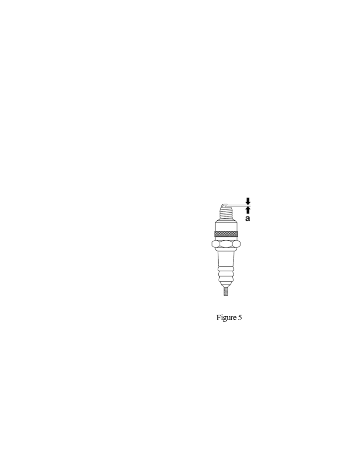
5.5 SparkPlug (Figure 5)
CAUTION: A loose spark plug can become very hot and may cause engine damage.
Clean or replace spark plug as needed to ensure proper operation. Refer to the engine
owner's manual.
The muffler becomes very hot during operation and remains hot for a while after stopping
the engine. Do not touch the muffler while it is hot.
Note: Refer to the Technical Data for the recommended spark plug type and the electrode
gap setting.
5.5.1 Remove spark plug and inspect it.
5.5.2 Replace plug if the insulator is cracked or
chipped.
5.5.3 Clean spark plug electrodes with a wire
brush.
5.5.4 Set the electrode gap (a).
5.5.5 Tighten spark plug securely.
16
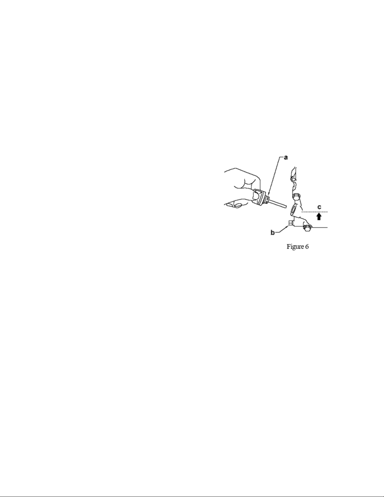
5.6 Engine Oil (Figure 6)
5.6.1 Drain oil while the engine is still warm.
5.6.2 Remove the oil fill plug (a) and drain plug (b) to drain oil.
Note: In the interests of environmental protection, place a plastic sheet and a container
under the machine to collect any liquid which drains off. Dispose of this liquid in
accordance with environmental protection legislation.
5.6.3 all drain plug.
5.6.4 Fill the engine crankcase through the oil
filler opening (b), to the upper mark on the
dipstick (c). Do not thread in the dipstick to check
the level. See Technical Data for oil quantity and
type.
5.6.5 When the crankcase is full, reinstall the
dipstick.
17
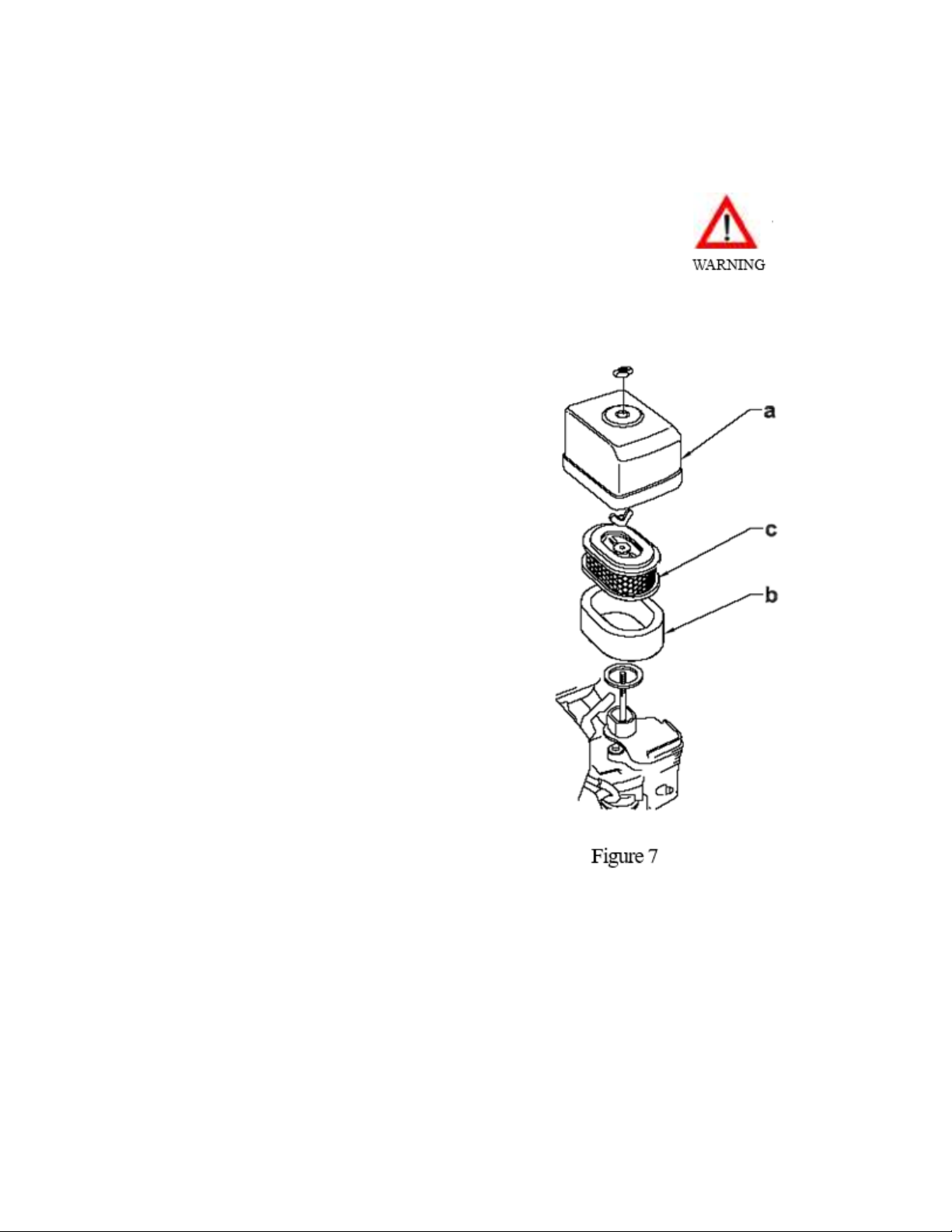
5.6 Air Cleaner (Figure 7)
CAUTION: NEVER use gasoline or other types of low flash point
solvents for cleaning the air cleaner. Afire or explosion could
result.
CAUTION: NEVER run engine without air cleaner. Severe engine
The engine is equipped with a dual element air
cleaner. Under normal operating conditions,
elements should be cleaned once every week.
Under severe, dry and dusty conditions, the
elements should be maintained daily. Replace an
element when saturated with dirt that cannot be
removed.
5.7.1 Remove the air cleaner cover (a). Remove
both elements and inspect them for holes or
tears. Replace damaged elements.
5.7.2 Wash the foam element (b) in a solution of
mild detergent and warm water. Rinse it
thoroughly in clean water.Allow the element to
dry thoroughly.
5.7.3 Tap the paper element (c) lightly to remove
excess dirt or blow compressed air through the
filter from the inside out. Replace the paper
element if it appears heavily soiled.
18
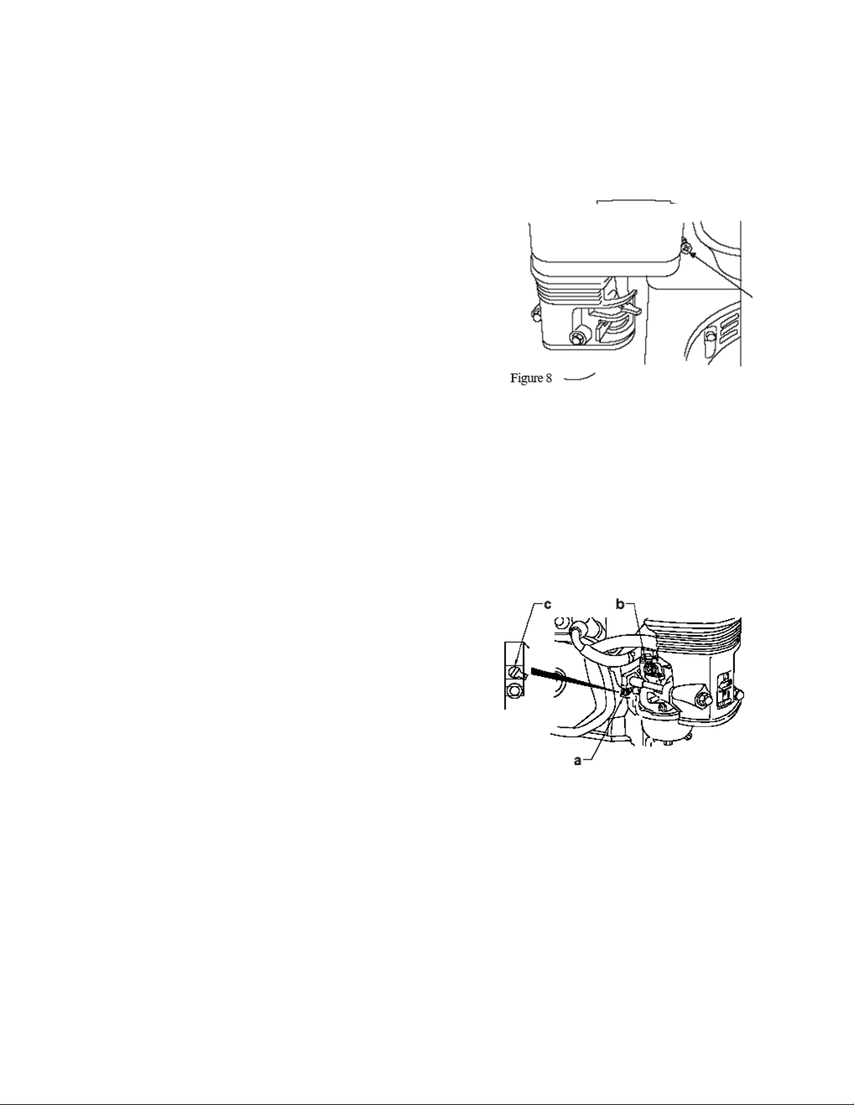
5.8 Cleaning Sediment Cup (Figure 8)
5.8 Carburetor Adjustment (Figure 9)
Note: On some engines, the pilot screw is fitted with a limiter cap (c) to prevent
excessive enrichment of the air-fuel mixture in order to comply with emission
regulations. The mixture is set at the factory and no adjustment should be necessary.
Do not attempt to remove the limiter cap. The limiter cap cannot be removed without
breaking the pilot screw.
5.8.1 Turn fuel valve off.
5.8.2 Remove sediment cup (a) and O-ring (b).
5.8.3 Wash both thoroughly in a nonflammable
solvent. Dry and reinstall them.
5.8.4 Turn fuel valve on and check for leaks.
5.9.1 Start the engine and allow it to warm up to
operating temperature.
5.9.2 Set the pilot screw (a) 2 turns out. See
Note.
5.9.3 With the engine idling, turn the pilot screw
(a) in or out to the setting that produces the
highest rpm.
5.9.4 After the pilot screw is adjusted, turn the
throttle stop screw (b) to obtain the standard idle
speed. See Technical Data.

19
5.10 Storage
5.11 Lifting the Machine
See Technical Data for the weight of the machine.
To lift machine manually:
5.11.1 Stop the engine.
5.11.2 Obtain help from a partner and plan the lift.
5.11.3 Grasp the machine by its cage (a) and lifting slot (b).
5.11.4 Lift the machine as shown.
5.11.5 Change engine oil and follow procedures described in engine manual for engine
storage.
5.11.6 Cover plate and engine and store in a clean, dry area
If plate is being stored for more than 30 days:
5.10.1 Remove loose stones and dirt from plate.
5.10.2 Clean engine cylinder cooling fins.
5.10.3 Clean or replace air filter.
5.10.4 Change exciter oil.

20
5.12 Transporting the Machine
To avoid burns or fire hazards, let engine cool before
transporting machine or storing indoors.
5.12.1 Turn fuel valve to the off position and keep the engine
level to prevent fuel from spilling.
5.12.2 Tie down machine on vehicle to prevent machine from
sliding or tipping over. Tie machine to vehicle at points shown on
Table of contents
Popular Trowel manuals by other brands

MULTIQUIP
MULTIQUIP Whiteman LD6SL Operation manual

Flextool
Flextool MQ WHITEMAN CA4HC operating instructions

Marshalltown
Marshalltown Speed Striker STRIKE45-L instructions

MULTIQUIP
MULTIQUIP Mikasa Series Operation and parts manual

Flextool
Flextool PORTATROWEL FPT30 operating instructions

ENAR
ENAR 600 Series user manual

Weber mt
Weber mt PG 90 E Series Operating and maintenance manual

Belle
Belle Pro 600X Operator's manual

Allen Engineering Corporation
Allen Engineering Corporation RAZORBACK RIDERS PRO1200C Operations manual and parts book

Euro Shatal
Euro Shatal ST92 - M12700.A - HONDA GASOLINE Operating instructions/spare parts list

BOMAX
BOMAX BM436 Operation manual

Lumag
Lumag BT900 Operator's manual


