Marshalltown Speed Striker STRIKE45-L User manual

1 of 14
WS1716
3-2017/Rev.A
STRIKE45-L
28166
Speed Striker™ Power Screed

2 of 14 WS1716
3-2017/Rev.A
TABLE OF CONTENTS
Safety Precaution ............................................... 2
Common Components ........................................... 3
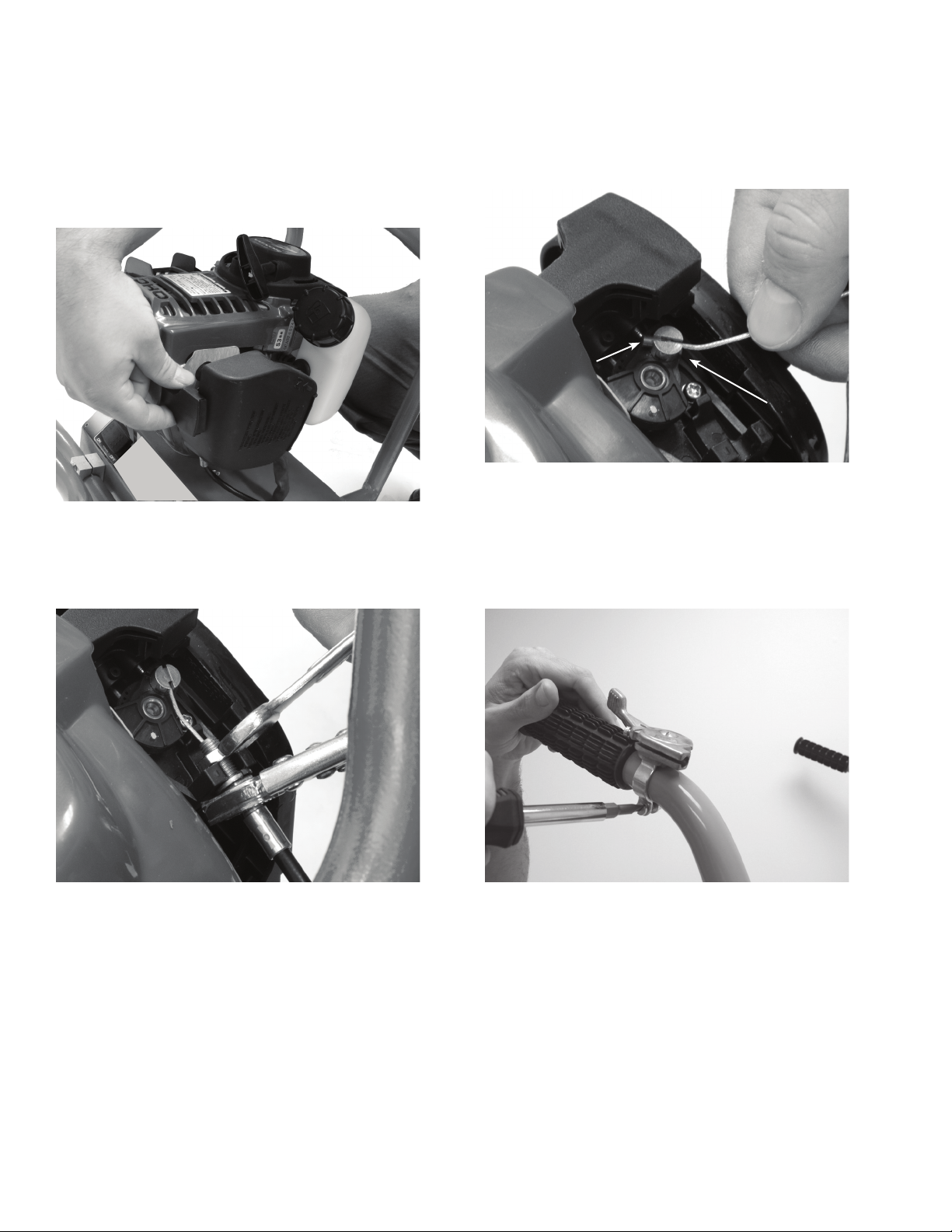
Assembly Instructions ..........................................4-6
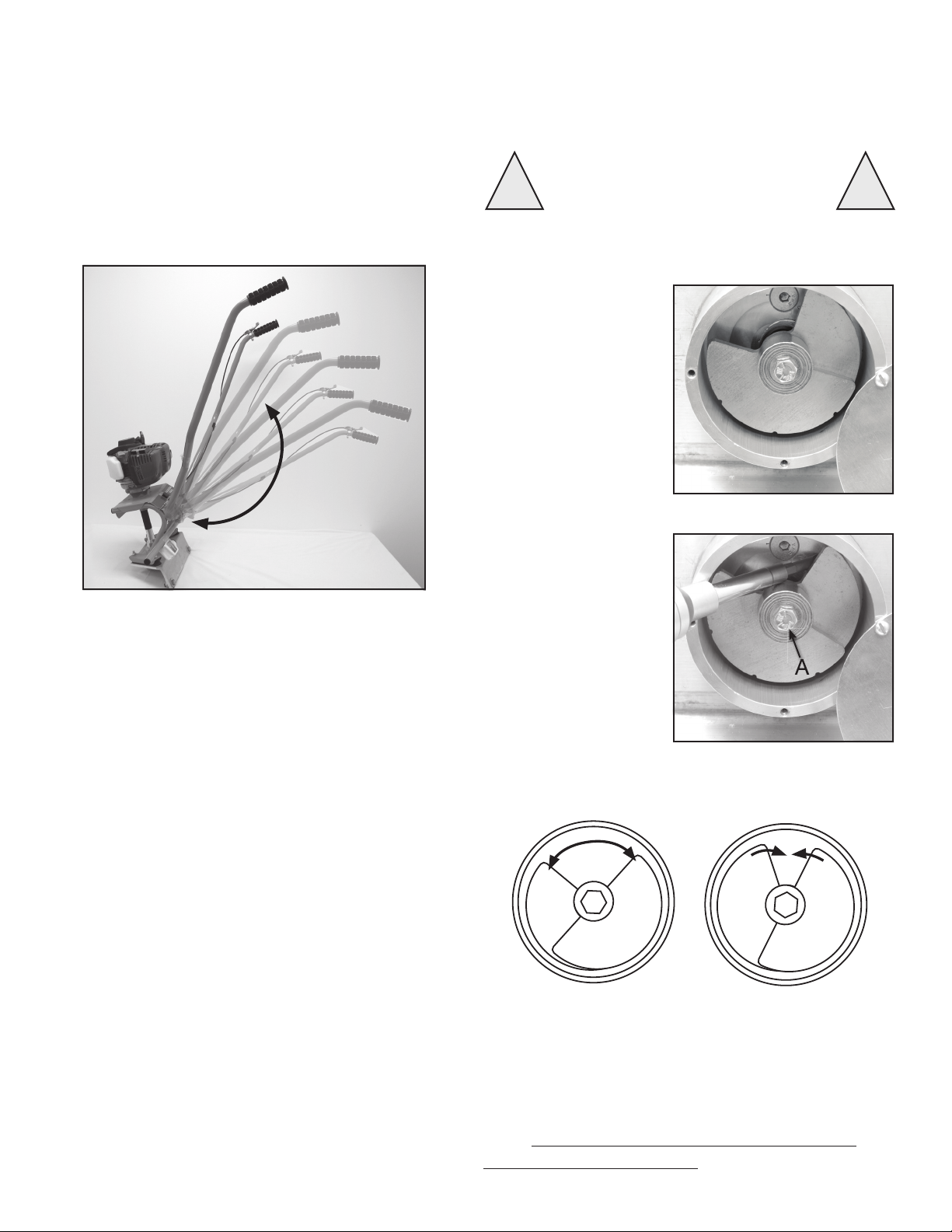
Machine Adjustments ............................................ 7
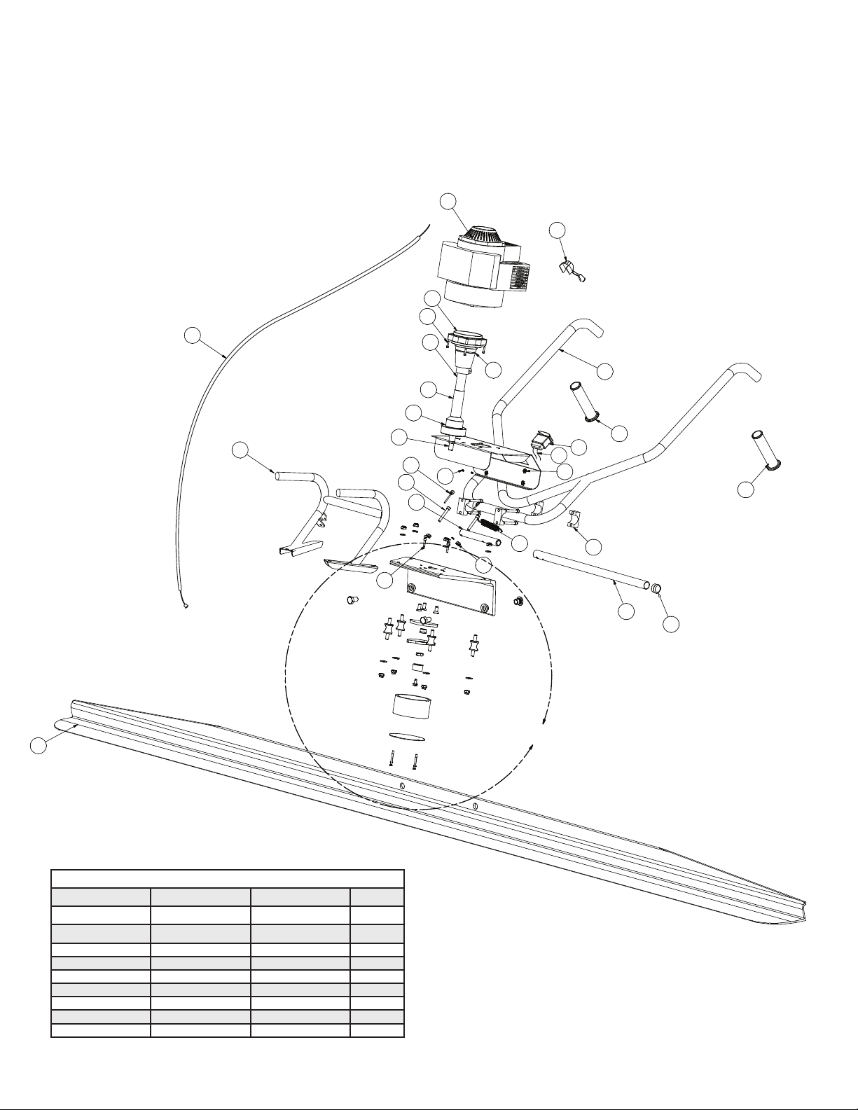
Parts Breakdown ..............................................8-9
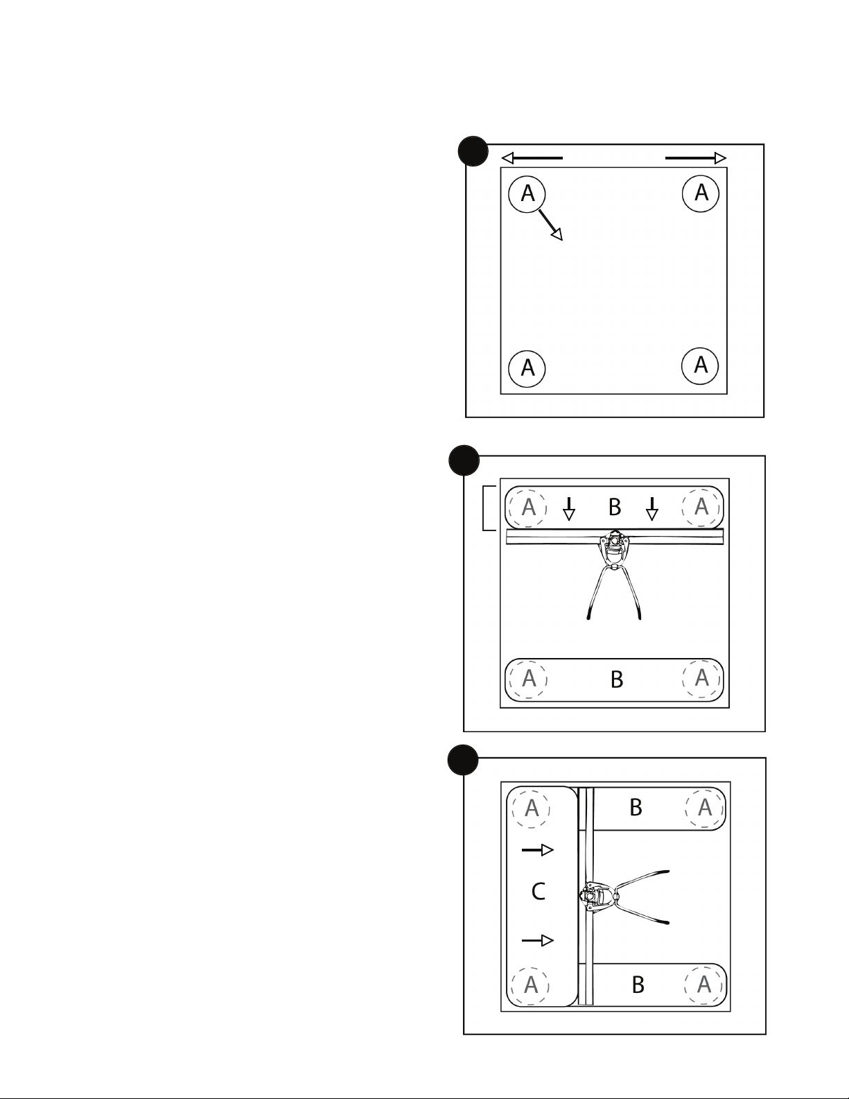
Wet Screeding ................................................ 10
Form to Form Screeding ........................................ 11
Technical Data/Capacities ....................................... 12
Maintenance Schedule.......................................... 12
How to Operate .............................................13-14
This machine was built with user safety in mind, however, it can present hazards if improperly operated and serviced. Follow
operating instructions carefully and use good judgement when operating!
CALIFORNIA PROPOSITION 65 WARNING: Operation of this equipment and/or engine exhaust from this product
contains chemicals known to the State of California to cause cancer, birth defects, or other reproductive harm.
SAFETY PRECAUTION
ALWAYS
• Always stop engine between loads of concrete
• Always screed while walking backwards
• Always clearly mark and be aware of all grade pins,
form stakes or other trip hazards
• Always follow all safety warnings and labels of the
engine manufacturer
• Always read and understand the owners manual of
the engine manufacturer
•
CAUTION!
Always wear approved hearing, eye and breathing protection
• Always use form oil to coat blade or other parts susceptible
to concrete build up (avoiding electrical connections) before
each use
• Always properly secure screed before transporting
• Always follow recommended maintenance schedules
• Always make sure all connections and fasteners are tight
before every use
• Always make sure engine is in "OFF" position when
servicing or not in use
• Always use in a well ventilated area
• Always keep Speed Striker™ and engine manual handy
on the job site
• Always replace parts as they become damaged or worn
NEVER
•
WARNING!
Never operate screed without all parts and safety
covers correctly attached
•
DANGER!
Never allow children to operate
• Never operate under the influence of drugs or alcohol
• Never use screed for anything other than its
intended purpose
• Never set eccentric weights to where excessive vibration
occurs at low RPM (weights too far open)
• Never set eccentric weights to where it takes excessive
RPM to make weights vibrate (weights too far closed)
• Never allow engine to run unattended or idle on
top of wet concrete
• Never place concrete higher than the leading
“curl edge” of the blade
•
WARNING!
Never fill gas tank while engine is running
•
WARNING!
Never start engine near spilt fuel
•
WARNING!
Never fill gas tank, operate, or service screed
near open flame
• Never use parts or blades from other manufacturers
• Never service a hot engine
• Never operate without proper training
• Never spray water or other liquid on a hot engine

3 of 14
WS1716
3-2017/Rev.A
2
14
4
3
5
17
6
8
9
10
11 13
15
16
COMMON COMPONENTS
1.
Start/Stop Switch
2.
Engine
3.
Recoil Starter
4.
Oil Cap
5.
Gas Cap
6.
Throttle Lever
7.
Handle Bar Mounting Blocks
8.
Handle Bars
9.
Kickstand
10.
Drive Shaft
11.
Vibration Dampeners
12.
Blade
13.
Eccentric Weight Cover
14.
Frame
15.
Board Mounting Plate
16.
Throttle Cable
17.
Air Filter
1
7
12

4 of 14 WS1716
3-2017/Rev.A
ASSEMBLY INSTRUCTIONS
Assembly is easy, following these steps:
INSTALLING HANDLE BARS AND KICKSTAND:
Step 1 – Remove the 4 hex screws (A) that hold down the two
handle mounting blocks.
Step 2 – Slide kickstand arm onto kickstand end and fasten
with nut & bolt (B) as shown
Step 4 – Making sure all mounting block and frame holes are
aligned, insert hex screws and tighten with 7/16" wrench or
socket.
Step 3 – Place handle bars into mounting blocks, making sure
handle bars are centered evenly across the mounting blocks.
A
A
A

5 of 14
WS1716
3-2017/Rev.A
INSTALLING THROTTLE CABLE:
Step 1 – Remove carburetor cover by pressing clips.
Step 4 – Attach the throttle lever to the handle, as shown
above.
Step 3 – Fasten the throttle cable as shown. Make sure
there is a nut on each side of plastic fitting. Make sure the
cable does not work itself out of the plastic fitting
while tightening.
Step 2 – The throttle has a rotating silver peg (A) with a slot
on one side of it. One end of the throttle cable has a metal
barrel (B) that fits into this slot. Insert barrel into the slot so
when the throttle cable is pulled, it will pull the throttle open
(toward the base plate of the screed).
ASSEMBLY INSTRUCTIONS
A
B

6 of 14 WS1716
3-2017/Rev.A
Step 7 – Secure throttle cable using clips,
as shown above.
Step 6 - Once cable is through throttle lever, return the
lever to the “idle” position shown above. Using pliers, pull
all extra slack out of the cable, making sure you are not
actually opening the throttle at the carburetor. Once all
slack is removed, tighten locking screw.
Note – the plastic housing of the throttle cable will fit up into
the throttle cable housing.
ATTACHING BLADE
Attach blade making
sure that it is posi-
tioned on the “back
side” of the base
extrusion. Be sure to
insert the plastic
spacer between the
blade and mounting
plate
Make sure bolts
are tight before
each use.
Step 5 – Thread the exposed metal end of the throttle cable
into the throttle lever. The lever will need to be “opened” to
expose the hole it fits into. Back out the set screw to allow
the cable to pass through.
ASSEMBLY INSTRUCTIONS
Plastic Spacer - insert between blade and mounting plate

7 of 14
WS1716
3-2017/Rev.A
MACHINE ADJUSTMENTS
HANDLE
Your screed handle can be adjusted for a customized fit.
ECCENTRIC WEIGHTS
The factory weight set-
ting will provide sufficient
board vibration for most
jobs. For jobs where low
slump or dry concrete is
being poured, the weight
can easily be adjusted to
allow for more vibration at
lower RPM.
Using a slotted screw-
driver remove the
eccentric cover. Using a
7/16" socket, loosen the
eccentric weight tightening
bolt (A). You will need
to wedge a screwdriver
against the weight to keep
it from turning while
loosening bolt.
ADJUSTABLE
The height of the handle can be adjusted right
below the motor
DECREASE
INCREASE
Increase vibration, increase the gap between the weights
by spreading them apart.
Decrease vibration, decrease the gap between the
weights. If imbalance is increased then use less engine
RPM. Note: Always check and retighten the eccentric
weights every 10 hours of use.
WARNING !!
Always make sure engine is stopped with switch in "OFF"
position before making adjustments.

8 of 14 WS1716
3-2017/Rev.A
DETAIL A
A
16
46
44
20
45
3
1
22
24
4
33
19
39
7
8
29
9
11
30
35
32
27
31
12
34
28
47
47
2
23
43
26
48
15
21
10
13
14
33
25
38 36
42
40
49
6
32
DET. QTY. DESCRIPTION
1 1 GX35 HONDA MOTOR
2 4 HANDLEBAR CLAMP
3 1 HANDLEBAR ASSEMBLY
4 1 BASE EXTRUSION
6 1 KILL SWITCH
7 4 VIBRATION ISOLATOR
8 1 ECCENTRIC WEIGHT #1
9 1 ECCENTRIC WEIGHT #2
10 1 ECCENTRIC SHAFT
11 1 ECCENTRIC WEIGHT BUSHING
12 1 WEIGHT ADJUSTMENT CAP
13 1 LOWER BEARING HOUSING
14 1 COUPLING DRIVE SHAFT
15 1 CLUTCH
16 1 FLEX SHAFT
19 2 BLADE ATTACHMENT NUT
20 1 BLADE
21 1 KICKSTAND END
22 1 KICKSTAND ARM
23 2 KICKSTAND EYEBOLT
24 1 KICKSTAND END CAP
25 1 SPRING
26 1 FRAME
27 1 ECCENTRIC COVER
28 1 ECCENTRIC COVER CAP
29 3 DRIVETRAIN BASE MOUNTING SCREW
30 1 ECCENTRIC WEIGHT JAM NUT
31 1 ECCENTRIC TIGHTENING CAP BOLT
32 2 BLADE ATTACHMENT BOLT
33 4 ECCENTRIC COVER MOUNTING SCREW
34 4 ECCENTRIC CAP SCREW
35 8 VIBRATION ISOLATOR NUT
36 4 WELD NUT FOR HANDLEBAR CLAMPS
39 4 VIBRATION ISOLATOR NUT
40 2 BLADE ATTACHMENT LOCK WASHER
41 4 HANDLEBAR CLAMP BOLT
42 2 KICKSTAND NUT
43 2 KICKSTAND BOLT
44 1 REPLACEMENT DRIVESHAFT CORE (NOT PICTURED)
45 1 THROTTLE LEVER ( FRICTION STYLE)
46 4 ENGINE MOUNTING BOLTS
47 2 HANDLEBAR GRIPS
48 1 THROTTLE CABLE
49 1 KILL SWITCH WIRING
DESCRIPTION DETAILS INCLUDED
GRIPS 47
HONDA ENGINE 1, 46
THROTTLE LEVER 45
THROTTLE CABLE 48
HANDLEBARS 3
HANDLEBAR CLAMPS W/HARDWARE 2, 41
HANDLEBAR CLAMP HARDWARE ONLY 41
ON/OFF SWITCH W/WIRES 6, 49
ON/OFF SWITCH WIRES 49
ECCENTRIC COVER W/HARDWARE 27, 28, 33, 34
KICKSTAND 21, 22, 23, 24, 25, 42, 43
KICKSTAND HARDWARE 23, 25, 42, 43
DRIVE TRAIN 10, 13, 14, 16, 29, 44
CLUTCH 15, 46
VIBRATION DAMPENING KIT 7, 35, 39
ECCENTRIC WEIGHTS & HARDWARE 8, 9, 11, 12, 30, 31
ECCENTRIC WEIGHT HARDWARE ONLY 11, 12, 30, 31
MACHINE BASE 4
BLADE LOCKING HARDWARE 19, 32, 40
DRIVE SHAFT 44
DRIVE SHAFT HOUSING 10, 13, 14, 16
FRAME ONLY 26
ECCENTRIC COVER HARDWARE ONLY 33, 34
PARTS BREAKDOWN

9 of 14
WS1716
3-2017/Rev.A
DETAIL A
A
16
46
44
20
45
3
1
22
24
4
33
19
39
7
8
29
9
11
30
35
32
27
31
12
34
28
47
47
2
23
43
26
48
15
21
10
13
14
33
25
38 36
42
40
49
6
32
PARTS BREAKDOWN
REPLACEMENT BLADES
EDI Part# SIZE-FT. SIZE-M
13336 SWBLADE4 4 1.2
19288 SWBLADE45 4.5 1.37
13281 SWBLADE6 6 1.8
13283 SWBLADE8 8 2.4
13284 SWBLADE10 10 3.0
28226 SSBLADE12-L 12 3.7
13290 SWBLADE14 14 4.3
13290 SWBLADE16 16 4.9
12950 SWBLADE16P2 16 (2 sets of mounting holes) 4.9

10 of 14 WS1716
3-2017/Rev.A
SETTING ELEVATION OF SLAB
• Use grade pins (A) to set height of slab
in the middle of the pour.
• Chalk line or expansion joint sets
elevation around walls.
• Form boards set elevation where
there are no walls.
MAKING WET PADS
1. Using hand float, make wet pads around all grade
pins (A).
Note: Make sure all wet pad distances
are shorter than the length of board
being used.
2. Use board to stretch from wet pad to wet pad form-
ing rows (B).
3. Once rows are formed, run screed board off of the
two rows leveling the previously untouched con-
crete (C) in between.
NOTE: Height of concrete in area (C)
must be slightly higher than wet
pad rows (B) prior to striking off.
Once floated, wet pads (B) and concrete (C) will all be the
same height
1Blade Length
12-18 inches
2
3
HOW TO WET SCREED
12-18 in.

11 of 14
WS1716
3-2017/Rev.A
Length of board should overlap form boards on both
sides of the pour
Keep bottom of blade as flat as possible while striking
off of forms
To ensure the longest possible board life, use the
lowest possible vibration setting in relationship to the
slump of concrete being used.
HOW TO SCREED FORM TO FORM
Excess Concrete
ELEVATED
TRAILING EDGE
An elevated trailing edge may provide an area
for concrete to build up resulting in a slab
elevation that is too high
Excess Concrete
ELEVATED
LEADING EDGE
An elevated leading edge can trap rocks
between the blade and forms resulting in a
slab elevation that is too high
Excess Concrete
BOARD KEPT FLAT
Keep bottom of blade as flat as possible while
striking off of forms
WIDTH OF SCREED BOARD
WIDTH OF FORM

12 of 14 WS1716
3-2017/Rev.A
Check and retighten eccentric weights Every 10 hours or every month
Check oil level Before each use
Change engine oil First month or 10 hrs. - 6 mo. or 50 hrs after
Check fuel level Before each use
Inspect air filter Before each use
Replace air filter Every 25 hours or every 3 months
Spark plug - check and adjust Every 100 hours or 1 year
Spark plug - replace Every 300 hours or 2 years
Cooling fins Every 50 hours
Electronic Connections Before each use
Check Nuts and bolts Before each use
Replace nuts and bolts As necessary
TECHNICAL DATA/CAPACITIES
CAUTION
MAINTENANCE
Model Number STRIKE45-L
Drive System Flexible Shaft
Weight 28.5 lbs. (12.9 kg)
Blade Lengths 4, 4.5, 6, 8, 10, 12, 14, 16'
1.2, 1.37, 1.8, 2.4, 3, 3.7, 4.3, 4.9M
Blade Weight 1.85 Lb./ft. 2.75(kg/m)
Engine Type 4-stroke, overhead cam, single cylinder
Engine Make Honda
Engine Model GX35
Engine Horsepower 1.3 hp (1.0kW) @ 7,000 rpm
Engine Displacement 2.18 cu-in (35.8cm3)
Spark Plug CM5H (NGK)
CMR5H (NGK)
Spark Plug Gap 0.60 - 0.70mm
(0.024 - 0.028 in)
Engine Speed - idle 3,100 ± 200 rpm
Oil Type - Engine SAE 10W-30 (refer to engine manual)
Oil Capacity - Engine 0.11 qt (3.5 oz., 0.10 L)
Fuel Type Pump octane rating 86 or higher (refer to engine manual)
Fuel Tank Capacity 0.166 US gal (0.63 L)
!!
Your screed ships with a
pre-measured bottle of oil (3.5 oz).
Do not at anytime have more than 3.5 oz. of
oil in the engine. Too much oil will foul out
the spark plug resulting in an engine that is
hard to start and keep running.

13 of 14
WS1716
3-2017/Rev.A
HOW TO OPERATE
FUEL AND OIL
Make sure gas tank has plenty of 86 octane or
higher gasoline. Your 4 stroke Honda engine used
straight gasoline, NEVER USE A GAS/OIL MIX.
Empty entire bottle of provided Honda engine oil
into crank case. 3.5 oz. is the maximum oil capac-
ity. NEVER OVERFILL.
STARTING
1. On a cold engine, move choke lever to CLOSED
position. To restart a warm engine leave choke in
OPEN position
2. Press priming bulb repeatedly until fuel can be
seen in the clear-plastic fuel-return tube
3. Press On/Off Switch to the On Position.
4. Pull the starter grip lightly until you feel resistance,
then pull briskly. Repeat until engine starts.
5. If the choke lever was moved to the CLOSED
position to start the engine, gradually move it to
the OPEN position as the engine warms up.
RESTARTING A WARM ENGINE
1. Leave the choke lever in the OPEN position.
2. If there is no fuel in the clear-plastic fuel-return
tube, press priming bulb repeatedly
until fuel can be seen in the tube.
3. Press On/Off Switch to the On Position
4. Pull the starter grip lightly until you feel resistance,
then pull briskly. Repeat until engine starts.
CLOSED
OPEN
1
2
3
4

14 of 14 WS1716
3-2017/Rev.A
Once the engine is warm and running by itself with the choke OPEN you can begin screeding concrete.
For specific instructions on Wet Screeding and Form to Form screeding please see pages 10 and 11.
1. Begin by placing concrete within your forms slightly higher than the forms themselves.
2. Place screed on top of concrete and start engine.
3. Increase engine RPM until the clutch engages causing the screed to vibrate.
4. Walking backwards, begin screeding concrete (see page 10 for Wet Screeding or Page 11 for Form to Form screeding).
5. Your throttle lever does not require constant contact, but you can adjust RPM and vibration to accommodate wet or dry concrete.
Dry or low slump concrete may require more vibration to level and screed
6. Continue moving backwards while keeping concrete placed in front of the blade. The roll back feature of the blade will keep help
keep concrete from sliding over the blade. Concrete placed too high may slide over the board! This could make the screed too
hard to pull and result in a slab that is out of level.
DO NOT OVER VIBRATE CONCRETE!
The following are signs of too much vibration:
• Excessive concrete splatter
• Blade sinking below wet pads
• Ripple or “wake marks” following the blade
• Concrete easily sliding underneath form boards causing dips along the form edge
Always remember, the less vibration the better. Use only enough vibration to be able to comfortably pull screed backwards, leaving
a smooth, level surface.
OPERATING ON WET CONCRETE
104 S. 8th Ave.
Marshalltown, IA
Phone 800-888-0127 / 641-753-0127
Fax 800-477-6341 / 641-753-6341
www.MARSHALLTOWN.com
This manual suits for next models
1
Table of contents
Other Marshalltown Trowel manuals
Popular Trowel manuals by other brands

MULTIQUIP
MULTIQUIP Whiteman JTN Operation and parts manual

MULTIQUIP
MULTIQUIP Whiteman series Operation manual

MBW
MBW F30 Operator's safety and service manual

Allen Engineering Corporation
Allen Engineering Corporation Mechancial Super Pro Series Operations & parts manual

MULTIQUIP
MULTIQUIP Whiteman HHNG5 parts manual

BETON TROWER
BETON TROWER BT900 HPFH24.1 instruction manual