Sitex MDA-4 Specification sheet

MDA-4 VHF/DSC/AIS MARINE
RADIOTELEPHONE
OPERATION &
INSTALLATION MANUAL

—I—
SI-TEX MDA-4 User Manual
RF Radiation Information
RF Radiation Profile
Your radio is designed and tested to comply with a number of national and international standards and guidelines (listed below)
regarding human exposure to radio frequency electromagnetic energy. This radio complies with the IEEE and ICNIRP exposure
limits for occupational/controlled RF exposure environment at operating duty factors of up to 50% transmitting. In terms of
measuring RF energy for compliance with the FCC exposure guidelines, your radio radiates measurable RF energy only while it is
transmitting (during talking in PTT mode), not when it is receiving (listening) or in standby mode.
The device complies with SAR and/or RF field strength limits of RSS-102 requirement
RF Radiation Safety
In order to ensure user health, experts from relevant industries including science, engineering, medicine and health work with
international organizations to develop standards for safe exposure to RF radiation. These standards consist of:
United States Federal Communications Commission, Code of Federal Regulations; 47CFR part 2 sub-part J;
American National Standards Institute (ANSI)/Institute of Electrical and Electronic Engineers (IEEE) C95. 1-1992;
Institute of Electrical and Electronic Engineers (IEEE) C95. 1 –1999;
International Commission on Non-Ionizing Radiation Protection (ICNIRP) 1998;
FCC Regulations
Federal Communication Commission (FCC) requires that all radio communication products should meet the requirements set forth in
the above standards before they can be marketed in the U.S, and the manufacturer SHAILpost a RF label on the product to inform
users of operational instructions, so as to enhance their occupational health against exposure to RF energy.
Part 15 Compliance
This equipment has been tested and found to comply with the limits for a Class B digital device, pursuant to part 15 of the FCC Rules.
These limits are designed to provide reasonable protection against harmful interference in a residential installation. This equipment
generates uses and can radiate radio frequency energy and, if not installed and used in accordance with the instructions, may cause
harmful interference to radio communications. However, there is no guarantee that interference will not occur in a particular
installation. If this equipment does cause harmful interference to radio or television reception, which can be determined by turning
the equipment off and on, the user is encouraged to try to correct the interference by one or more of the following measures:
●Reorient or relocate the receiving antenna.
● Increase the separation between the equipment and receiver.
● Connect the equipment into an outlet on a circuit different from that to which the receiver is connected.
● Consult the dealer or an experienced radio/TV technician for help. Note: “Changes or modifications to this unit not expressly
approved by the party responsible for compliance could void the user’s authority to operate the equipment.”
EU Regulatory Conformance
As certified by the qualified laboratory, the product is in compliance with the essential requirements and other relevant
provisions of the Directive 1999/5/EC. Please note that the above information is applicable to EU countries only.

—II—
Warning- Limitations on Use
This MDA-4 product contains simple PPI chart, only as an aid to navigation for reference. Only Official Government Charts
and Notice to Mariners contain all the current information needed for safe navigation. This products feature cannot be relied
on as complete or accurate and may vary depending on location. It’s the captain’s responsibility to use official government
charts, notices to mariners, caution, sound judgment and proper navigational skills when operating their boat using this
product.

Contents
Contents............................................................................................................................................3
1 .Installation.....................................................................................................................................1
2. Front Panel/Back Panel/Wiring diagram.......................................................................................2
OptionalAccessories Handset/Back Panel/Wiring diagram Handset ...............................................4
3.LCD Display..................................................................................................................................6
4. Main Menu Operation on Screen..................................................................................................6
DSC Menu ................................................................................................................................6
MY MMSI ID setup..................................................................................................................7
Individual Call/Position Request/Group Call/Test call .............................................................8
All Ship Call .............................................................................................................................9
Receive Call Log.....................................................................................................................10
Send Call Log .........................................................................................................................10
Phone Book.............................................................................................................................11
DSC Setup...............................................................................................................................11
Main Menu..............................................................................................................................11
VHF Operation................................................................................................................12
GPS Setup.......................................................................................................................13
MDA-4AIS Setup...........................................................................................................13
ATIS Operation...............................................................................................................14
DSC Operation................................................................................................................15
System Config.................................................................................................................15
Distress Menu & Send the Distress Message..........................................................................15
MDA-4AIS Operation............................................................................................................16
5.Key Operation..............................................................................................................................18
Power on/off & rotate to get up/down function ......................................................................18
Special Function of DISTRESS key & Real-time DSC..........................................................18
VOL/AIS Control....................................................................................................................18
TRIW/HAIL (Tri Watch/Hailer) .............................................................................................19
Squelch/MOB Key..................................................................................................................19
DW/ FOG (Dual Watch/Foghorn)...........................................................................................19
MEM Key ...............................................................................................................................19
Scan Key.................................................................................................................................19
Hi/Lo.......................................................................................................................................20
LOC/DX..................................................................................................................................20
16/9 Key..................................................................................................................................20
Select second priority channel ................................................................................................20
CALL/MENU .........................................................................................................................21
Back Light...............................................................................................................................21
CH/*/WX (WX Channel:Only available for USA,Canada)....................................................21
6.Other Features and Solutions.......................................................................................................21
Special function keys..............................................................................................................21

TX Time Out...........................................................................................................................22
The Local Time & Date on Screen:.........................................................................................22
NMEA 0183 and NMEA 2000................................................................................................22
Appendix B –Channel List.............................................................................................................23
International Marine VHF Channels & Frequencies........................................................23
U.S. Marine VHF Channels and Frequencies..................................................................25
Notes:.....................................................................................................................................26
Specification..........................................................................................................................31

—1—
1 .Installation
Yoke Mount Installation:
1.Place and fasten the mounting bracket on the console by 4 screws;
2. Mount the radio onto the bracket;
3. Attach the supplied mounting knobs from two sides of the bracket to fix the base radio securely in the
mounting bracket (as shown above)..

—2—
Flush mount installation:
Insert 4 screws to surface mount the radio to the console as pictured above
2. Front Panel/Back Panel/Wiring diagram
Front Panel

—3—
1、CH/*/WX—short press to enter private channel, long press to enter weather channel(only available in US)
2、Back Light On/Off—short press to back light On/Off.
3、Call/MENU—short press to enter “DSC Menu”, long press to enter “Main Menu”.
4、16/9—short press to enter channel 16 or press this button to quit all other modes and back to the priority channel
quickly, long press will get second-priority channel 09 or any channel that you’ve set as second-priority channel.
5、LOC/DX—short press to get conversion between local and distance mode (DX allows normal receive sensitivity; and
“LOCAL”eliminates receiver noise, but degrades receiver sensitivity meanwhile “LOCAL”icon display on LCD).
6、HI/LO—short press to toggle between 25watt and 1 watt output. “HI”or “LO”icon appears on LCD display to indicate
setting.
7、SCAN—short press to enter all scan/all memory scan, long press to enter priority all/memory scan.
8、MEM—short press to enter memory mode, long press to save/delete memory channel.
9、DW/FOG—short press to enter Dual Watch Mode, long press to enter “Foghorn Menu”.
10、SQL/MOB—short press to get SQL setting, long press to get MOB activated.
11、TRIW/HAIL—short press to enter Tri Watch Mode, long press to enter “HAILER LISTEN MODE”and set volume as
you wish.
12、VOL/AIS—short press to enter volume set, long press to enter AIS (Automatic Identification System)
13、Handset connector.
14、Generally it activates the “Exit”icon shown on screen. On initial screen, it also acts as the UP key function;
15、Soft key--short press to get channel up, long press to make channel up much faster.
16、Soft key--short press to get channel down, long press to make channel down much faster.
17、Generally it acts enter function as “Enter”icon show on screen.At INITIAL screen, it also acts Down key function;
18、DISTRESS—Pull up key cover and press to start DistressAlert Calling if you programmed your radio with an MMSI
Number.
19、Power on/off—short press to turn it on, long press to turn it off. Rotate knob to get up/down function when radio is on.
PTT key—remote command microphone push this key to sent out radio frequency signals

—4—
Optional Accessories Handset/Back Panel/Wiring diagram Handset
Back Panel
(1)RF antenna
(2)Power +
(3)Power -
(4)Hailer
(5)external speaker jack
(6)Smart GPS/NMEA 0183
(7)NMEA 2000
(8)GND hole
(9)remote command microphone
PTT
DISTRESS
EXIT
UP
DOWN
ENTER
—5—
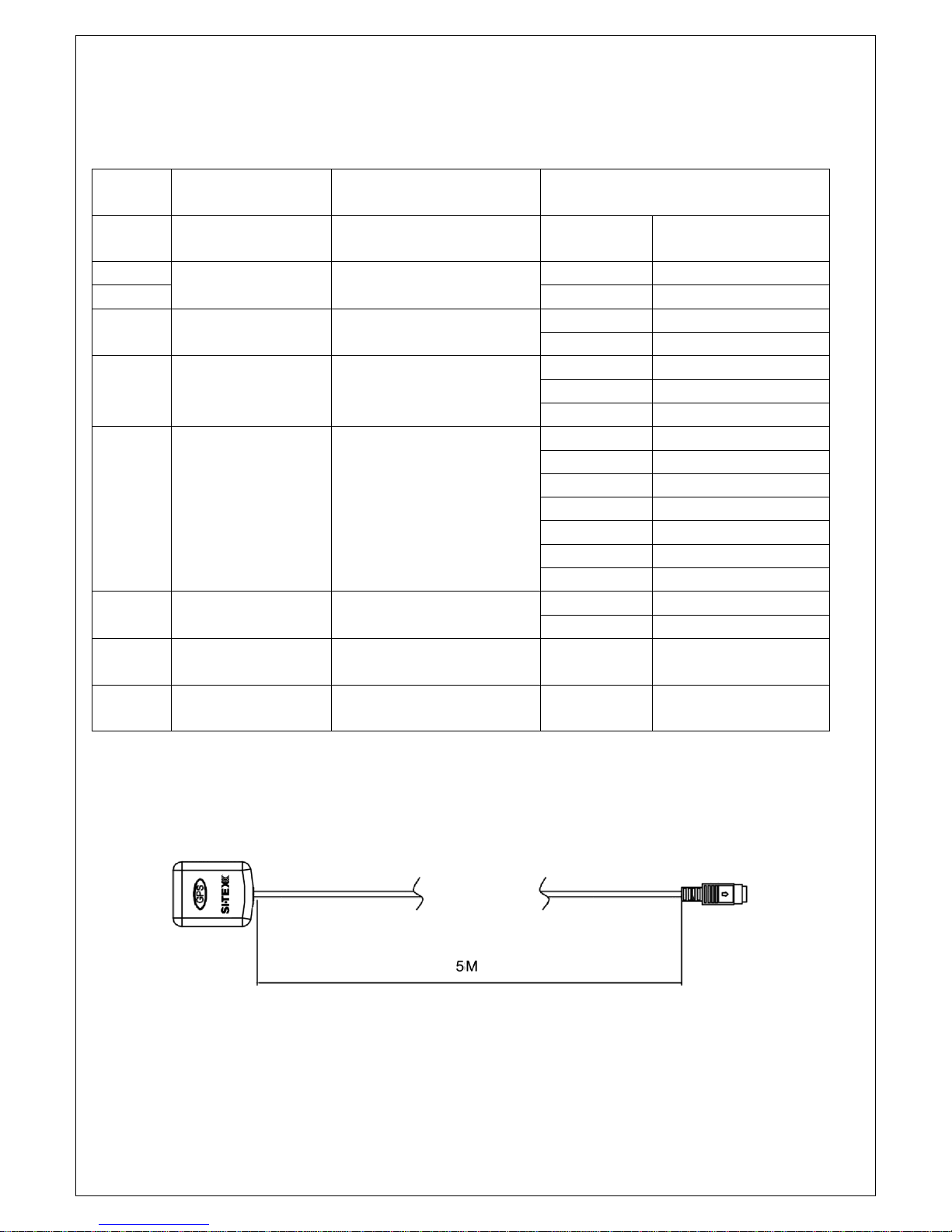
As above show, the “number in picture”correspond to “wiring number”also correspond to “the number in the below table”
The details please check the below table
Serial
Number
General
Description
Function Description
Different Color Description
(1)
RF antenna
connector
connect with antenna
﹨
﹨
(2)
Red & Black
Power
Power supply
Red
Power+ +13.8V
(3)
Black
Power- GND
(4)
Audio Connector
Black Phone Jack
Hailer
White
HAILER+
Black
HAILER-
(5)
Audio Connector
Black 3.5 mm Jack
External Speaker
White
AUDIO+
Bare
AUDIO-
Red
NC
(6)
Smart-GPS
connector
Smart GPS
&
NMEA0183
Red
USBRX
Yellow
+5V
Green
USBTX
Black
MINIGPS_RX
Brown
NC
Qrange
MINIGPS_TX
Bare
GND
⑺
Connector
NMEA2000
White
\
Bule
\
⑻
GND connection
hole
﹨
﹨
﹨
(9)
remote command
microphone
﹨
﹨
﹨
Optional accessories smart GPS- 5 m Connector

—6—
3.LCD Display
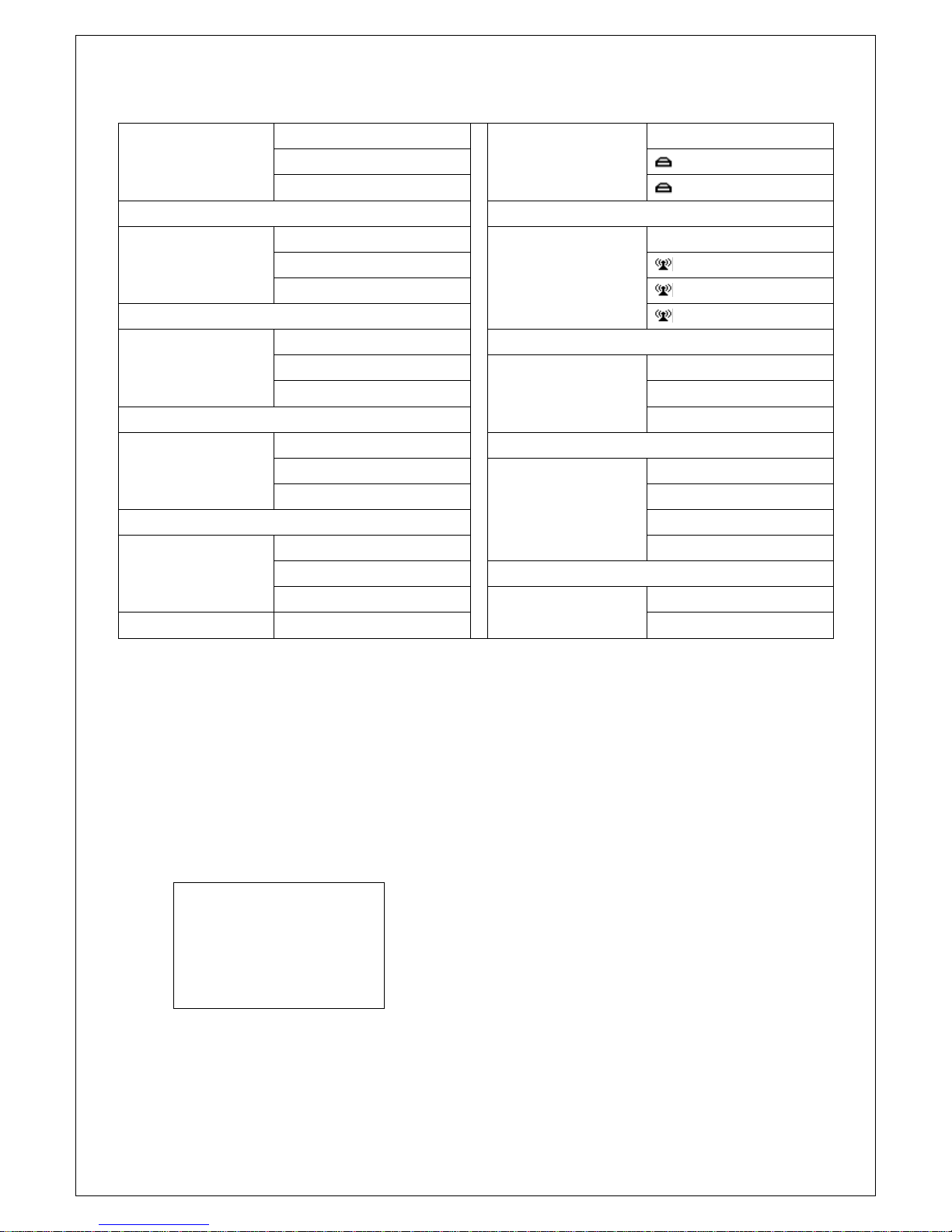
4. Main Menu Operation on Screen
DSC Menu
Short press the CALL/MENU key will be displayed as below on LCD:
DSC Menu
Individual Call
Position Request
All Ship Call
Group Call
Test Call
Receive Call Log
Send Call Log
Phone Book
DSC Setup
My MMSI ID
EXIT ▲▼ENTER
—7—
Detailed entrance for each catalogue as shown below:
Individual Call►
Individual Call
Receive Call Log►
Receive Call Log
Input Address
Distress Call
From Phone book
Others Call
Position Request►
Position Request
Send Call Log►
Send Call Log
Input Address
Distress Call
From Phone book
MOB Call
Others Call
All Ship Call►
All Ship Call
Safety
Phone Book►
Phone Book
Urgency
Buddy List
Group List
Group Call►
Group Call
Input Address
DSC Setup►
DSC Setup
From Phone book
Position Input
Position Reply
Test Call►
Test Call
Test Ack
Input Address
From Phone book
My MMSI ID►
My MMSI ID
100000008
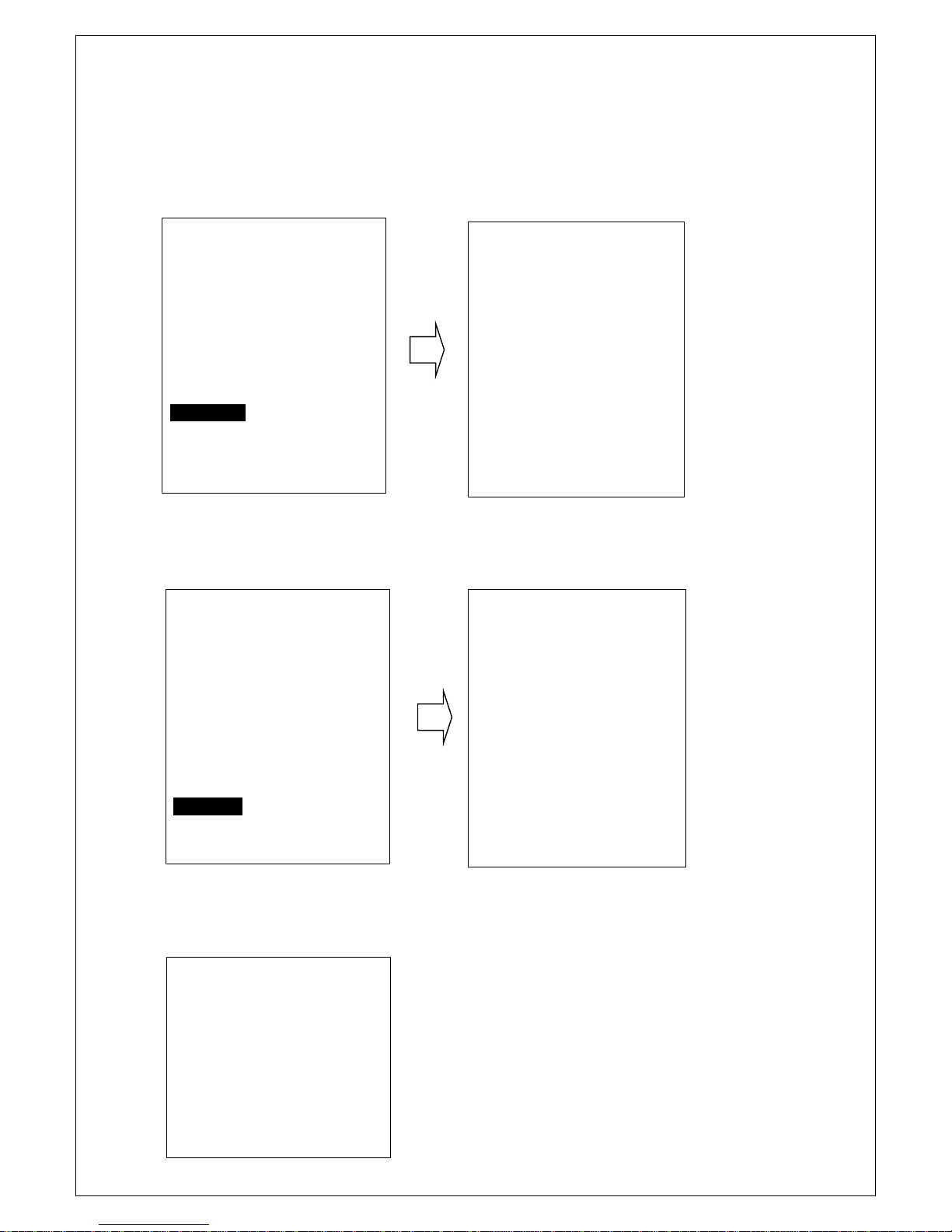
MY MMSI ID setup
Firstly, long press CALL/MENU key to enter “Main Menu”.
Secondly, select “DSC Operation”to enter “MY MMSI ID”.
Then you can set up your related MMSI ID as below, generally you need to double confirm the MMSI ID. Once confirmed,
your MMSI ID will be locked by this radio.
My MMSI ID
123456789
EXIT

—8—
When input 9 digits, UP/DOWN key used for choosing the number from 1 to 9. You need to input all numbers from the left
to right one by one until all finished. Once fulfilled 9 digits, then press “ENTER”to confirm.
Individual Call/Position Request/Group Call/Test call
Press the “CALL/MENU”key and choose “Individual Call”, then choose “Input MMSIAddress”or “From Phonebook”.
Take individual call as example—
First select the “Input Address”, then Then select the type of individual call such as
input 9 MMSI digits manually such as Routine
123456789 for your address as below:
Next select the preferred channel such
as 01 port operation and confirm to call
My MMSI ID
Input MMSI
123------
EXIT ▲▼ENTER
My MMSI ID
123456789
EXIT
Individual Call
Routine
EXIT ▲▼ENTER
InputAddress
Input 9 digits
0-----------
EXIT ▲▼ENTER
Individual Call
Select Channel:
01 port ops/vts
03 unauthorized
05 port ops/vts
06 inter ship
07 commercial
08 commercial
EXIT ▲▼ENTER
Individual Call
To: 100000000
Safety
Telephony by
Channel 01
EXIT CALL

—9—
Then the individual call is sent as below shown
All Ship Call
Select the All Ship item The All Ship Call is sent.
DSC USA
1W
16
SQL:5
VOL:4 SAFETY
Elapsed 00:56
EXIT
DSC Menu
Individual Call
Position Request
All Ship Call
Group Call
Test Call
Receive Call Log
Send Call log
Phone Book
DSC Setup
My MMSI ID
EXIT ▲▼ENTER
All Ship Call
Safety
Urgency
EXIT ▲▼ENTER
Safety
Select Channel:
01 telephone
02 telephone
03 telephone
04 port ops
05 port ops/vts
06 safety
07 port ops
08 commercial
EXIT ▲▼ENTER
All Ship Call
To :All Ship
Safety
Telephone by
Channel 01
EXIT CALL
DSC USA
1W
16
SQL:2
VOL:4 DISTRESS
Elapsed 00:04
EXIT

—10—
Receive Call Log
When received DSC, you can check those messages from the “Distress Menu”and see the exact message.
Send Call Log
Press “CALL/MENU”key to choose “Send Call Log”item and see previous distress call, MOB call and other call that you
have sent.
DSC Menu
Individual Call
Position Request
All Ship Call
Group Call
Test Call
Receive Call Log
Send Call Log
Phone Book
DSC Setup
My MMSI ID
EXIT ▲▼ENTER
Receive call log
Distress call
Others call
EXIT ▲▼ENTER
Received DSC
Distress cancel
Undesignated
From: 123456789
GPS POS: Unknown
Time: Unknown
EXIT DELETE
DSC Menu
Individual Call
Position Request
All Ship Call
Group Call
Test Call
Receive Call Log
Send Call Log
Phone Book
DSC Setup
My MMSI ID
EXIT ▲▼ENTER
Send Call Log
Distress Call
MOB Call
Others Call
EXIT ▲▼ENTER
—11—
Phone Book
Press “CALL/MENU”key to choose “Phone Book”item and can check the contacted ship by “Buddy List”and
“Group List”
DSC Setup
Main Menu
Long press the CALL/MENU key will display as below:
DSC Menu
Individual Call
Position Request
All Ship Call
Group Call
Test Call
Receive Call Log
Send Call Log
Phone Book
DSC Setup
My MMSI ID
EXIT ▲▼ENTER
Phone Book
Buddy List
Group List
EXIT ▲▼ENTER
DSC Menu
Individual Call
Position Request
All Ship Call
Group Call
Test Call
Receive Call Log
Send Call Log
Phone Book
DSC Setup
My MMSI ID
EXIT ▲▼ENTER
DSC Setup
Position Input
Position Reply
Test Ack
EXIT ▲▼ENTER
Main Menu
VHF Operation
GPS Setup
AIS Setup
ATIS Operation
DSC Operation
System config
EXIT ▲▼ENTER

—12—
Detailed entrance for each catalogue as shown below:
VHF Operation
Channel Band Set
ATIS Operation
My ATIS ID
Priority 2nd Ch
ATIS Function
GPS Setup
GPS Source
DSC Operation
My MMSI ID
GPS Setting
DSC Function
NMEA0183 Setting
System Config
Back Light Time
AIS Setup
AIS Output
LCD Contrast
AIS Display Set
Key Beep
AIS Alarm
Version Info
Factory Reset
VHF Operation
Long press the CALL/MENU key to enter “VHF Operation”item as below for setup:
For priority 2nd Ch, you can select your preferred channel from below as your priority second channel.
Main Menu
VHF Operation
GPS Setup
AIS Setup
ATIS Operation
DSC Operation
System Config
EXIT ▲▼ENTER
Priority 2nd Ch
Select Channel:
01 telephony
04 sar
05 port ops/ vts
06 inter ship
07 commercial
08 commercial
EXIT ▲▼ENTER
VHF Operation
Channel Band Set
Priority 2nd Ch
EXIT ▲▼ENTER
Channel Band Set
USA
√INT
CAN
EXIT ▲▼ENTER

—13—
GPS Setup
Long press the CALL/MENU key to enter “GPS Setup”item for setup as below shown.
Main Menu
VHF Operation
GPS Setup
AIS Setup
ATIS Operation
DSC Operation
System Config
EXIT ▲▼ENTER
Follow like this, you can setup your priority as you wish.
MDA-4 AIS Setup
Long press the CALL/MENU key to enter “AIS Setup”item for setup as below shown
Main Menu
VHF Operation
GPS Setup
AIS Setup
ATIS Operation
DSC Operation
System Config
EXIT ▲▼ENTER
GPS Setup
GPS Sourceource
GPS Setting
Smart GPS Baud
EXIT ▲▼ENTER
GPS Source
√Smart GPS
NMEA2000
EXIT ▲▼ENTER
AIS Setup
AIS Output
AIS Display Set
AIS ALARM
EXIT ▲▼ENTER
AIS Output
All Off
NMEA0183
NMEA2000
√N0183+N2000
EXIT ▲▼ENTER
AIS Display Set
SHIP MMSI
√SHIP Name
EXIT ▲▼ENTER
AIS ALARM
CPA ALARM
CPA Range
TCPATime
EXIT ▲▼ENTER
CPA ALARM
√Disable
Enable
EXIT ▲▼ENTER
GPS Setting
Time display
Time offset
COG/SOG Display
EXIT ▲▼ENTER

—14—
CPA Alarm enable Choose“Disable”or“Enable”item to enter disable or enableAIS alarm, then press
“ENTER”key to confirm.
CPARange (Closest point of approach)Alarm distance setup
Press UP/DOWN key to input digital one by one, after you have done this, press “ENTER” key to confirm, the maximum
input range is 25.0NM, if the input value over than 25.0NM, than this operation is invalid, the system will ask for re-enter,
the default CPA value is 1.5 NM.
TCPA(Time closest point of approach)Alarm distance setup
Press UP/DOWN key to input digital one by one, after you have done this, press “ENTER” key to confirm, the maximum
input range is 30 minutes, if the input value is over than 30 minutes, the input is invalid, then the system will ask for re-enter,
the default CPA value is 10:00 Min.
ATIS Operation
Long press the CALL/MENU key to enter “ATIS Operation”for setup.
Main Menu
VHF Operation
GPS Setup
AIS Output
ATIS Operation
DSC Operation
System Config
EXIT ▲▼ENTER
ATIS Operation
MyATIS ID
ATIS Function
EXIT ▲▼ENTER
CPA Range
Input Range
01.5NM
EXIT ▲▼ENTER
TCPA Time
Input Time
10:00Min
EXIT ▲▼ENTER

—15—
Choose to press for setup or more function as you wish.
DSC Operation
Long press the CALL/MENU key to enter “DSC Operation”for setup.
(My MMSI ID setup have been explained in previous chapter, please see Page**)
System Config
Long press the CALL/MENU key to enter “system config”for setup.
Main Menu
VHF Operation
GPS Setup
AIS Setup
ATIS Operation
DSC Operation
System Config
EXIT ▲▼ENTER
Choose to press for setup or more function as you wish.
Distress Menu & Send the Distress Message
Pull the DISTRESS red cover and press the DISTRESS key. Then below “Distress Menu”will be displayed on LCD.
Main Menu
VHF Operation
GPS Setup
AIS Setup
ATIS Operation
DSC Operation
System Config
EXIT ▲▼ENTER
DSC Operation
My MMSI ID
DSC Function
EXIT ▲▼ENTER
Distress Menu
Undesignated
Fire, Explosion
Flooding
Collision
Grounding
Capsizing
Sinking
Adrift
Abandoning
System Config
Back Light Time
LCD Contrast
Key Beep
Version Info
Factory Reset
EXIT ▲▼ENTER
Table of contents


-(301) Operation and installation")


