Rhotheta RT-1000 User manual

User Manual
RT-1000
Antenna
VHF Bearing-System

RT-1000 Antenna
RHOTHETA Page 2 of 30 User Manual
Edited by:
RHOTHETA Elektronik GmbH
Kemmelpark
Dr.-Ingeborg-Haeckel-Str. 2
82418 Murnau
Germany
Tel.: +49 8841 4879 - 0
Fax: +49 8841 4879 - 15
Internet: www.rhotheta.de
E-Mail: [email protected]
Copyright © RHOTHETA Elektronik GmbH
All rights reserved
-Issue: 2016/11/04 [Rev 1.01.a]
-Document-ID: 12-9-2-0019-3-1-60
Note
The manufacturer reserves the right to make modifications at any time and without previous
information of the here described product.

RT-1000 Antenna
RHOTHETA Page 3 of 30 User Manual
Content
1
General Information.........................................................................................................4
1.1
Reflections and their Influence to the Bearing Result. ...........................................................................5
1.2
Influence of the signal ground reflection to the DF accuracy.................................................................9
2
Antenna Construction...................................................................................................14
2.1
Side View..............................................................................................................................................14
2.2
Bottom View..........................................................................................................................................15
2.3
Component List.....................................................................................................................................16
3
Assembly Instructions ..................................................................................................17
4
North Alignment of the Direction Finder Antenna and Determining the System
Accuracy at the Installation Site .........................................................................................19
4.1
North Alignment Using a Ground Transmitter (Pre-setting) .................................................................19
4.2
Flight Checking for Exact North Alignment and Determining the System Accuracy at the Antenna
Installation Site...............................................................................................................................................21
4.2.1
Determining the Position Using a Theodolite ..........................................................................22
4.2.2
Determining the Position Using a GPS Receiver ....................................................................22
4.2.3
Simplified Method ....................................................................................................................22
4.3
Evaluation.............................................................................................................................................23
4.3.1
Evaluation of Direction Finding Signal.....................................................................................23
4.3.2
Evaluation of QDR Live Display (Green Light Dot Circle) .......................................................25
4.3.3
Evaluation of Measuring Results.............................................................................................26
4.4
Determining the North Correction.........................................................................................................28
5
Mechanical Dimensions................................................................................................29
6
Notes...............................................................................................................................30

RT-1000 Antenna
RHOTHETA Page 4 of 30 User Manual
1 General Information
DF-Systems are used to locate aircraft, ships, vehicles or persons who have a radio
transmitter. All prevalent DF-Systems determine the direction from which the signal reaches
the DF-Antenna. If this direction is the same as the direction to the aircraft, vessel or the
vehicle, everything is fine. If the radio signal arrives, the DF-Antenna not in a direct way,
because of shadowing or reflections, the direction finder shows in the direction to the
reflector, where the signal (or the majority of the signal) comes from.
This direction can have a big difference to the direction of the source of the signal, the aircraft,
the vessel or the vehicle where the transmitter is located. The operator will regard this as a
malfunction of the direction finder. In the physical way, this is not true. The problem is that the
bearing we get from the DF is not the information the operator desires.
This means for the praxis, that we have to find an antenna location, where the radio signals
always arrive the antenna in the direct way.
The achievable bearing accuracy depends largely on the physical conditions at the antenna
location.
The remote concept of the RT-1000 C DF-System separates the antenna and the high
frequency components (RF-Antenna, Receiver Unit) from the controller side (Controller) with
the signal processing. So it is easy to place the antenna somewhere in the open field where
the physical conditions are good, while the Controller is located at the tower side.
The following information should help you, to find a physical convenient antenna location.

RT-1000 Antenna
RHOTHETA Page 5 of 30 User Manual
1.1 Reflections and their Influence to the Bearing Result.
The antenna of a DF-System can be seen as a sensor, which analyses the incoming
electromagnetic wave field to find out where it comes from. As the waves on quiet water
surface also radio waves in the free (unobstructed) field dispread circular from around the
transmitter.
Sender Empfänger
Sender Empfänger
Dipol Dipol
Weg
0 0 0 0 00 0 0 0 0
+ + + + +
-
bei v = c
Grad
Isophasen
a)
b)
---
v = Ausbreitungsgeschwindigkeit
c = Lichtgeschwindigkeit
= Wellenlänge
λλ
Fig. 1: Free-space propagation of radio waves
Fig. 1 gives an extremely simplified representation of even radio wave propagation in free
space. The sine wave in part a) corresponds to the instantaneous value of the electric field on

RT-1000 Antenna
RHOTHETA Page 6 of 30 User Manual
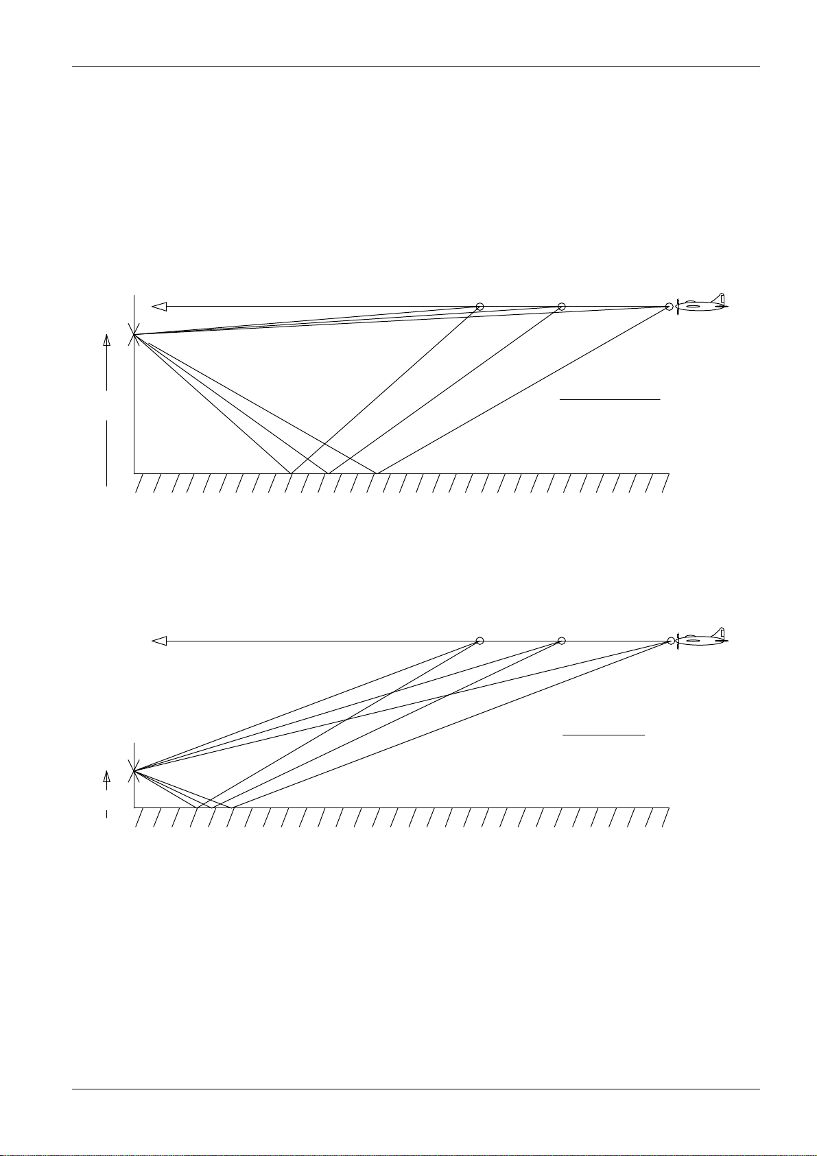
the plane path to the receiver. Part b) is the vertical projection of part a). The circles represent
the lines of equal phase relations for even waves.
If the distance between transmitter and receiver is adequate, these are practically straight
lines when they reach the receiver location. Such an idealized situation is not to be found in
built-up areas, and especially not in mountainous regions. In such areas, the propagation path
is obstructed by obstacles, mirror reflectors; diffuse reflectors with and without absorption
characteristics, diffracting edges and resonators. Reflectors and conducting rods are effective
as resonators if their size is approximately that of the wavelength to be received. Therefore,
reflections increase as wavelengths become shorter, diffractions at edges however are
reduced and so the effect of shadowing obstacles is more important.
Accordingly, the propagation characteristics of radio waves from approximately λ< 10 m
increasingly resemble those of light.
At a wavelength of 1 m to 3 m, wave propagation requires a direct path and if this is not
available, only reflected waves are received. In urban areas, these may come from several
directions simultaneously. But that is not all: the mostly horizontal or vertical plane polarized
waves propagated by the transmitter are also rotated to a certain degree due to diffuse
reflectors and diffracting edges. When the wave arrives at the receiver, it may be oblique,
elliptically, or even circular polarized. This fact becomes apparent by the often curious
antenna positions which are necessary to obtain the best reception of radio or television
waves.
These points are meant to indicate that in the VHF, UHF range, direction finding of a
stationary transmitter using a stationary direction finder in a built-up area or even inside a
building is practically impossible.
Transmitter Reflection
2
Fig. 2: Field of lines of equal phase relations for two coherent waves

RT-1000 Antenna
RHOTHETA Page 7 of 30 User Manual
Conditions at airports are much more favourable. These instructions are intended to allow the
best positioning of the direction finder antenna.
Of course, airports are not without reflectors, but these do not normally cause noticeable
problems. All direction finders with field probes calculate the angle of signal incidence by
finding out the path direction (vector), at which the largest phase modification per unit of
distance is present.
In Fig. 1 this vector is vertical to the lines of equal phase relations. Fig. 2 shows the distorted
field of lines of equal phase relations for two coherent waves (reflection) from different
directions with different field strengths.
Mainly 4 parameters influence the deviation of the bearing caused by reflections:
1. Position of the DF antenna
2. Position for the Transmitter antenna
3. Position of the reflector
4. Wave length of the signal (signal frequency)
The advantage of wide base direction finders is most noticeable in static conditions. Static
conditions indicate that the position of the transmitter and direction finder as well as the
transmitter frequency does not change with time. Should one of the three named items
change (e.g. transmitter in aero-plane) the direction finder antenna and the field of lines of
equal phase relations begin to move in relation to one another. This movement accelerates in
proportion to the relationship between the reflected path distance and the direct path distance
of the radio wave (Fig. 3).
As shown in Fig. 2, this movement in the case of wide base direction finders causes slight
azimuth oscillation. In contrast, this oscillation is larger in the case of narrow base direction
finders - the series of small circles in Fig. 2. When several values are averaged out however,
both systems give the same azimuth.

RT-1000 Antenna
RHOTHETA Page 8 of 30 User Manual
R1
R2
W1 W2
Reflector
Aeroplane
Direction finder
W2 W1
Reflector
Aeroplane
R1
R2
a) b)
Direction finder
Fig. 3: Reflected path distance an direct path distance of the radio wave
favourable: unfavourable:
W1/W2 » R1/R2 W1/W2 ≈R1/R2
With moving transmitter:
Rapid phase shifting between W and Only very slow phase shifting between W and
R signal, therefore good bearing average. R signal, so no averaging possible. The
possible displayed bearing oscillates slowly
around the rated value.
The following conclusions can be drawn:
Vertical reflector surfaces e.g. buildings, hangars, metal fences, metal masts, overhead
lines as well as bushes and trees should not be within 100 m of the direction finder
antenna if possible.

RT-1000 Antenna
RHOTHETA Page 9 of 30 User Manual
1.2 Influence of the signal ground reflection to the DF accuracy
The signal out of an aircraft transmitter will reach the DF antenna on the direct way. In
addition a part of the signal will be reflected on the ground and will reach the antenna as well.
Depending on the angle of incidence and the height at which the DF antenna is located above
the ground, the direct signal and the reflected signal have to go different distances.
W
W
W
R
R
R
R
R
R
W
Ground
Ground
h = large
h = small
unfavourable
favourable
a)
b)
A moving transmitter causes rapid
phase shifts between W and R signals
and therefore a lot of amplitude
fluctuations at the direction finder.
A moving transmitter causes slow
phase shifts between W and R signals
and therefore few amplitude fluctuations
at the direction finder.
Fig. 4: The phases between a direct wave W and a reflected wave R
This is the reason why there are angles of the signal incidence, where the signals are in
phase and there are angles where the signal arrive the antenna in opposite phase. On one
case the direct and the ground signal add each other, on the other case the direct signal is
compensated or reduced by the ground reflected signal. This is the reason why the vertical
antenna diagram become more zero points as higher the antenna is placed (see Fig. 5).

RT-1000 Antenna
RHOTHETA Page 10 of 30 User Manual
Vertical diagram for h = 23 m Vertical diagram for h = 3.5 m
Fig. 5: Signal strength lobes plotted against angle of elevation
The zeros of the vertical diagram can be determined using the following formula:
n
h
2
tan
λ
α
=
; f
c
0
=
λ
;
s
m
c
299792458
0
=
c
0
= light velocity [m/s]
λ= wave lengths of the signal [m]
h = height of the antenna head above the ground [m]
n = ordinal numeral of the zero point (1. 2. 3….)
f = signal frequency [Hz]

RT-1000 Antenna
RHOTHETA Page 11 of 30 User Manual
By itself, zero point in the vertical antenna diagram will not cause bearing failures. It will only
cause a significant reduction of the signal field strength. The ground will absorb a part of the
signal so not 100% will be reflected. In the praxis the direct incoming signal and the ground
reflected signal will not compensate each other, so that even an attenuated signal is received.
In the area of the zero points of the antenna diagram, the direct signal from the aircraft will be
attenuated by the ground reflection. All other signals, which reach the antenna via horizontal
reflectors, will be not attenuated and become now strong in relation to the direct signal. The
DF is not able to distinguish between direct and reflected signals. It shows the direction to
reflector where now the strongest signal comes from. If an aircraft fly through the maxima’s
and minima’s of the DF antenna, while it approach the airport, significant bearing value
fluctuations can occur. The cause is that alternately, the field strength of the direct, or of the
reflected signal, will predominate (see Fig. 6).
If the antenna is mounted on the RHOTHETA antenna mast RT-1306, the antenna head is
about 4 Meters above the ground. The 1
st
zero point will be in an elevation of approx.
17°above the horizon.
In the areas which are relevant for the air traffic controller (report points, traffic pattern …), the
aircrafts stay below of the first zero point.
The roof of the tower is in physical respect, the worst antenna position you can find on an
airfield. The very high antenna position with it’s the unfavourable vertical antenna diagram, in
combination with a lot of building around it, as well as other antenna systems and reflectors
on the tower roof will influence the DF results in the most applications in a not acceptable
way. The full performance of the DF system, you will get here only in very rarely cases.
The following conclusion may be drawn:
The best position for a direction finder antenna is on a flat surface at a distance from
vertical reflectors, only 3.5 to 4 m above the ground.
Summary we can say:
An antenna location in a free area, a few meters above the ground and in a ambit of some
100 meters free of reflecting obstacles, will give satisfying bearing results. An antenna
position more than 10 meter above ground can be a problem and should be checked out by a
flight test before final installation.

RT-1000 Antenna
RHOTHETA Page 12 of 30 User Manual
Reflector
Reflector
Reflector
Reflector
Reflector
112 050 153 349 270 230270270
270
10 m
Nullstelle
Nullstelle
Nullstelle
Nullstelle
Nullstelle
N u ll s t e ll eN u l ls t e ll eN u ll s t el l eN u ll s t e ll e
N u ll s t el l e M a x i mu m
M a xi m u mM a xi m um
Maximum
Ma x imu m
Maximum
Maximum
Maximum
Peilantenne
Fig. 6: Influence of ground reflection to the bearing result

RT-1000 Antenna
RHOTHETA Page 13 of 30 User Manual
In order to carry out checking and acceptance, the direction finder is subjected to a "flight
test" (Fig.7). By means of circular flights approx. 5 to 10 km away, the angular accuracy and
influences due to vertical reflectors are calculated. These circular flights should be carried out
in both directions in order to eliminate any possible "lag error" in the direction finder display.
The aeroplane is tracked using a theodolite erected next to the direction finder antenna and
angle values from this are compared with those from the direction finder display. It is also
possible to do it with a GPS based procedure. Here the exact DF antenna position is stored
as a way point in the GPS of the aircraft or vessel. While the test flight the pilot gives the GPS
bearing to the DF side. Here it both bearings can be compared. RHOTHETA can support you
in this matter with an automatic test recording system.
During the radial flights, the aeroplane flies across the direction finder from various directions
to find out detrimental ground reflections and the cone of silence, the area above the direction
finder where no usable information can be gained from the direction finder. These over-flight
measurements are especially important for testing the usefulness of a direction finder antenna
set-up on the tower.
Direction finder antenna place
Circular flight
Fig. 7: Surveying the direction finder using radial and circular flights

RT-1000 Antenna
RHOTHETA Page 14 of 30 User Manual
2 Antenna Construction
2.1 Side View
02
01
03
04
05
06
07
08
Fig. 8: RTA 1300.A Direction Finder Antenna

RT-1000 Antenna
RHOTHETA Page 15 of 30 User Manual
2.2 Bottom View
09
10
11
12
13
14
15
16
17
18
Fig. 9: RTA 1300.A Direction Finder Antenna (Bottom View)
X 17

RT-1000 Antenna
RHOTHETA Page 16 of 30 User Manual
2.3 Component List
Installation of the Antenna
Pos.
Connector
Function
1 Lightning conductor rod
2 Radiator cover
3 Radiator
4 Clamping nut
5 Radiator flange
6 Antenna head
7 North dipole label
8 Mast tube
9 X 21 Flat plug for control cable connection
10 X 13 Flat plug for control cable connection
11 X 17 Flat plug for control cable connection
12 X 15 Flat plug for control cable connection
13 X 19 Flat plug for control cable connection
14 Radiator housing
15 BNC jack for antenna cable
16 Cord grip
17 X 22 Flat plug for control cable connection
18 Radiator housing cover

RT-1000 Antenna
RHOTHETA Page 17 of 30 User Manual
3 Assembly Instructions
Installation of the Antenna
Step
Description
1 Fit the O-ring on mast tube
O-ring
2 Pull the antenna cable through the mast tube
3 Connect RF cable to the BNC connector
4 Screw cord grid tight to clamp the RF cable
5
Plug the control cables into the connection board
•
Push back guard sockets
•
Using pointed flat-nose pliers, grip the flat plug covers and push fully onto the
flat plugs.
•
Push guard sockets back on again.
RF connection
Connection board
Cord grip tight
X22
X19
X15
X17
X13
X21
Connection ground
brown
Connection west signal
orange
Connection east signal
yellow
Connection south signal
green
Connection north signal
black
Connection +15 V voltage
red
Allocations of Connections
Connector (Name)
Control Cable Colour
Signal
X22 (GND) brown Earth
X13 (NORTH) black North dipole control current
X17 (SOUTH) green South dipole control current
X15 (EAST) yellow East dipole control current
X19 (WEST) orange West dipole control current
X21 (+15 V) red 15-V supply voltage

RT-1000 Antenna
RHOTHETA Page 18 of 30 User Manual
Installation of the Antenna
Step
Descripti
on
6 Apply a thin coat of grease to the
antenna head/mast tube contact faces.
7 Screw antenna head onto mast tube.
8 Fit O-ring to lightning conductor rod
9 Apply thin coat of grease to antenna
head/lightning conductor rod contact
faces.
10 Screw lightning conductor rod onto
antenna head.
11
Fix radiators
•
Push clamping nut, clamping cone,
washer and rubber seal onto
radiator.
•
Push radiator fully into recess for
radiator.
•
Carefully tighten clamping nuts
12 Erect mast tube (if not already done)

RT-1000 Antenna
RHOTHETA Page 19 of 30 User Manual
Installation of the Antenna
Step
Description
13 Earth mast tube
14 Align antenna
Point north dipole (marked by red point on radiator housing) northwards
Warning
Observe all appropriate guidelines, especially VDE regulations when conducting all building
work, installation of electrical equipment and lightning protection measures.
Caution
LED-based obstacle lights should not be used. LED-based obstacle lights may disturb the
reception of the DF system due to the integrated power supply.
The use of the RHOTHETA obstacle light as defined in the options list will prevent such
problems.
4 North Alignment of the Direction Finder Antenna and
Determining the System Accuracy at the Installation
Site
The north alignment is used to harmonize the angle determined by the direction finder with
the actual (magnetic) north-related azimuth values.
4.1 North Alignment Using a Ground Transmitter (Pre-setting)
Pre-setting, which requires further correction by the north adjustment on the DF Channel in
the ±90 range (resolution 0.5°) as described in DF Channel user manual, is achieved by the
mechanical alignment of the direction finder antenna.

RT-1000 Antenna
RHOTHETA Page 20 of 30 User Manual
Nevertheless, the setting of the antenna should be carried out as accurately as possible since
this makes subsequent measurements easier.
Procedure:
1. Mount the direction finder antenna on the antenna mast so that it is free to rotate. Point
the marked dipole to the north. For the RTA 1306 Antenna Mast, loosen the clamping
screws provided for the purpose.
2. Switch on the direction finding system. Set the north adjustment to zero. Carry out a
phase adjustment.
3. Set up a transmitter at an adequate distance (at least 100 m). From there, use a
compass to determine the direction to the direction finder antenna.
Caution
When measuring using the compass, ensure that during the measurement there
are no objects (transmitters, cars..) in the vicinity of the compass which could affect the
magnetic field.
Caution
While doing measurements with a compass, be sure that nothing is around which can
influence the magnetic field. This can cause a big failure in you measurement
4. Activate the transmitter and transmit a continuous signal.
For hand held radio units it is advisable to hold the unit above your head. In this case, the
antenna points vertically upwards.
Caution
When transmitting with a monopole antenna
(e.g. a hand held unit), care must be taken due to undefinable
radiation conditions to ensure that the antenna is as free as
possible from disturbance, i.e. vertically installed.
Other manuals for RT-1000
7
This manual suits for next models
1
Table of contents
Other Rhotheta Marine Radio manuals
Popular Marine Radio manuals by other brands

Garmin
Garmin VHF 300 - Marine Radio instruction manual

F.u.n.k.e.
F.u.n.k.e. 800ATC-H-260-260 Operation and installation

DIGITAL YACHT
DIGITAL YACHT AIT2000 Technical notes

Thrane&Thrane
Thrane&Thrane SAILOR 6222 VHF DSC user manual

FUHR
FUHR autotronic 834 installation instructions

Weatherdock
Weatherdock easyTRX3 Quick Instruction