Sitron SLU User manual

Installation Manual
1
Ultrasonic Level Meter SLU
It is highly recommended that the user carefully read all of the instructions in this manual before installation or
use of the level meter for the first time. Keep the manual in a safe place. The manufacturer reserves the right to
implement changes without prior notice.

2
Safety All operations described in this instruction manual should be carried out only by trained personnel or an
accredited person. Warranty and post warranty service must be exclusively carried out by the manufacturer.
Improper use, installation or set-up of the level meter can result in undesirable results (overfilling of the tank
or damage of system components).
The manufacturer is not responsible for improper use, losses of work caused by either direct or indirect
damage, and for expenses incurred during installation or use of the level meter.
Measuring Principle
The SLU Ultrasonic level meters are compact measurement devices containing an ultasonic transmitter and an
electronic module. The transducer generates ultrasonic pulses that travel at the speed of sound toward the target
medium. These sound waves are reflected off the surface of the medium and are received by the transducer system.
The “time of flight” between the transducer and the surface and then back to the transducer is measured. Based on the
time period during which the individual pulses spread towards the level and back, this period is averaged by the
electronics (that also performs temperature compensation) and subsequently are converted to an output current
4...20mA with HART protocol or output RS-485 Modbus and the measured value is displayed on the display.
The central processor evaluates and blocks out interfering signals, performs temperature compensation, compares the
cleaned received signal with the false reflection map (e.g. from mixers, ladders, reinforcement etc.) and selects a
suitable reflection (echo).
The SLU ultrasonic level meters are suitable for continuous non-contact level measurement of liquids (water, waste
water sewage, etc.), mash and paste materials (sediments, resins etc.) in closed or open vessels, sumps, reservoirs
and open channels. In the case of bulk-solid materials, the measuring range is reduced, but can be amplified or
compensated by using the horn accessory.
Variant of Sensor
- SLU-02 - Measuring range from 0.15m - 2m plastic PVDF transmitter and plastic body (PP+HDPE),
process connection with thread G 1"
- SLU-06 - Measuring range from 0.25m - 6m plastic PVDF transmitter and plastic body (PP+HDPE),
process connection with thread G 1.1/2"
- SLU-10 - Measuring range from 0.4m - 10m plastic PVDF transmitter and plastic body (PP+HDPE),
process connection with thread G 2.1/4"
- SLU-20 - Measuring range from 0.5m - 20m plastic PVDF transmitter and plastic body (PP+HDPE),
aluminum alloy flange
Installation Manual
3
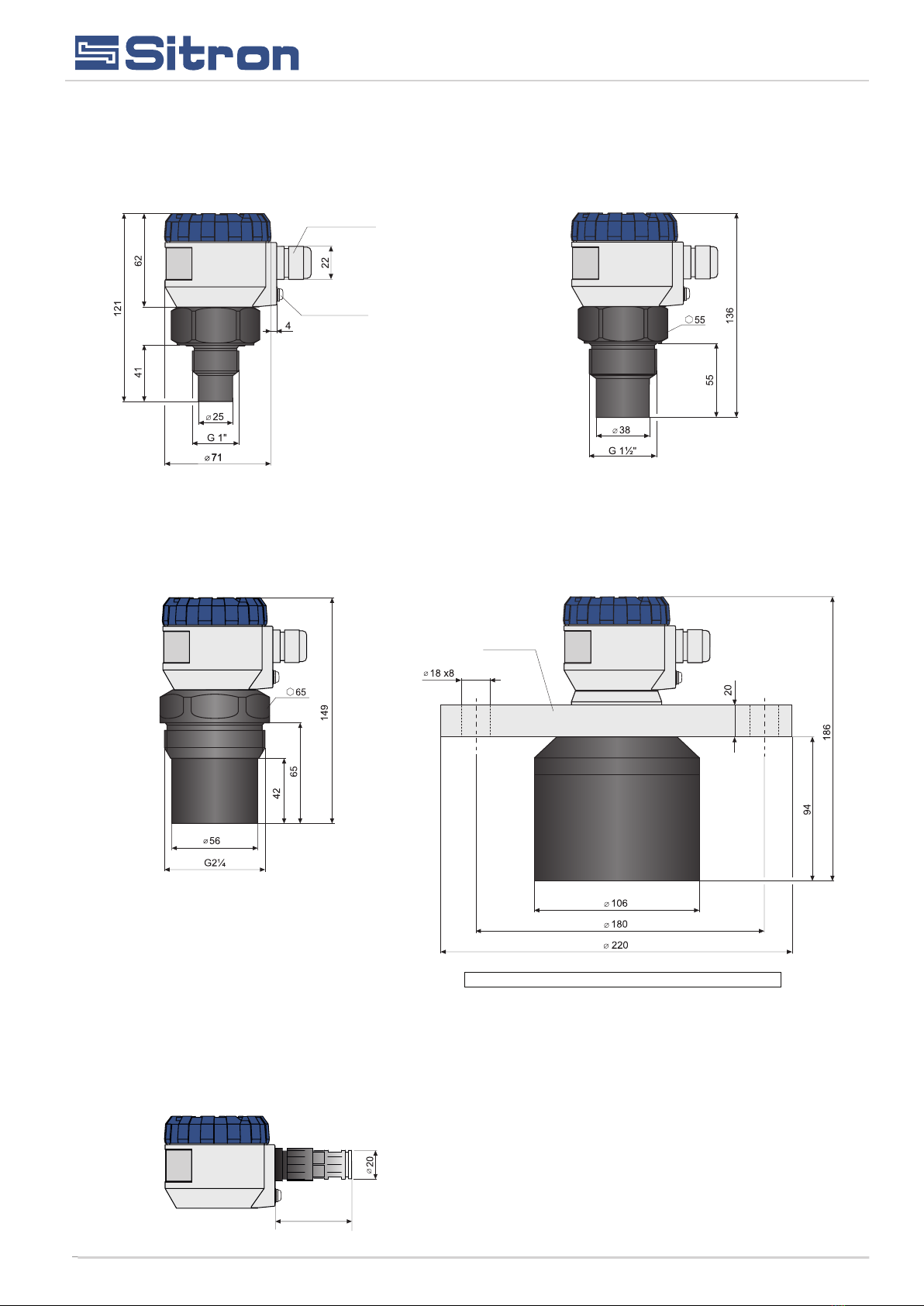
Dimensional Drawings
Variant SLU with protective
cable shield
Al alloy,
DN100
Pg11
cable gland
ground terminal
Flange (for type 20) according to standard: DIN 2527, PN10
SLU02 SLU06
SLU10 SLU20
50
Installation Manual

Fig. 2: Level meter dead zone
m – Dead zone
(blind zone, blocking distance)
-
Fig. 3: Installation distance from the tank wall
SLU–02 ; 10 d > 1/12 c
(min. 200 mm)
SLU–06 d > 1/8 c
(min. 200 mm)
SLU–20 d > 1/10 c
(min. 200 mm)
Fig. 4: Possible installation of the installation neck
a – Neck height
b – Neck width
m – Dead zone (blind zone, blocking dist.)
SLU–02 ; 06 a < 3 b
b > 100 mm
SLU–10 a < 1.5 b
b > 100 mm
SLU–20 a < 1.5 b
b > 150 mm
d – Distance from
the tank wall
c – Maximum reach
of the level meter
4
Installation Instructions
Install the level meter in the vertical position into the upper lid of the tank or vessel or
reservoir using a the threaded connection, a fastening nut or a flange so that the level
meter axis is perpendicular to the surface level of the measured liquid( Fig.1)
The min. dimensional parameters to install the level meter in to a lid or a celling of tank are
givening (Fig.3)
When installing in an open channel (reservoir, drain etc.) install the level meter on to a
bracket as close as possible to the expected max. level.
Each measuring range of SLU models has a specified ‘‘dead zone’. This means that
within the first 10 to 50 centimers (depending on the model) below the transmitter, no
signal reflected in this area can be evaluated. The dead zone (Fig.2) determines the min.
distance possible between the level meter and the highest surface level. The min.
distances to the medium are given in the chapter ‘Specifications’.
It is necessary to install the level meter so that the target level will not interfere with the
dead zone when filled up to the maximum level. If the measured level interferes with the
dead zone, the level meter will not work supply the correct output signal.
Fig.1 Recomended installation
in the tank
d – Distance from
the tank wall
c – Maximum reach
of the level meter
If the maximum surface level in the tank interferes with the dead zone, the level mater has to be mounted higher within a
neck extention to the tank. In this way, the tank can be filled to the maximum volume. The inner neck surface has to be
even and smooth (without edges and welded points) the inner edge should be rounded where the ultrasonic wave
eminates from the pipe. The neck diameter should be as large as possible but the neck height should be as low as
possible, minimizing the extra distance between the medium and the sensor. Recommended dimensions of the
extended neck are given in (Fig.4).
Installation Manual
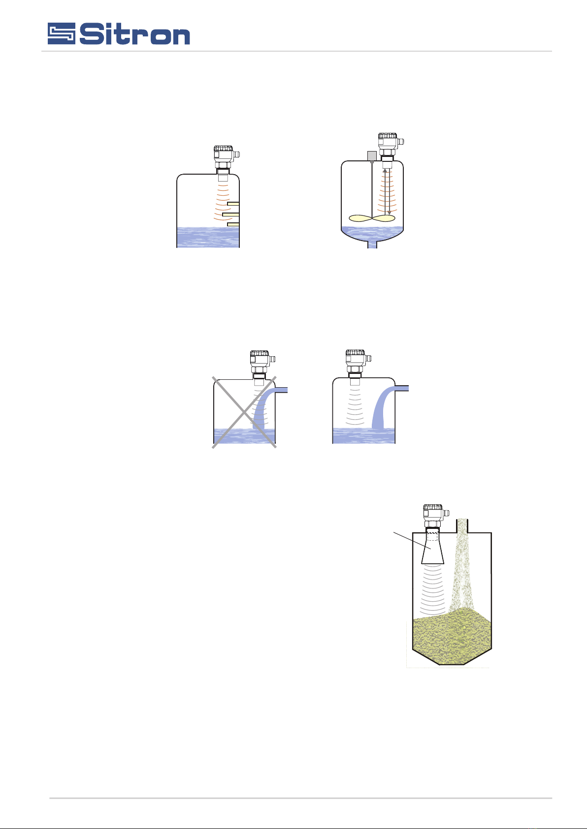
Fig. 5: False echo from obstacles in the tank Fig. 6: False echo from the mixer paddle
Fig. 7: Level meter installation outside the influence of filling
Fig. 8: Level meter installation in silo or hopper
horn
adapter
5
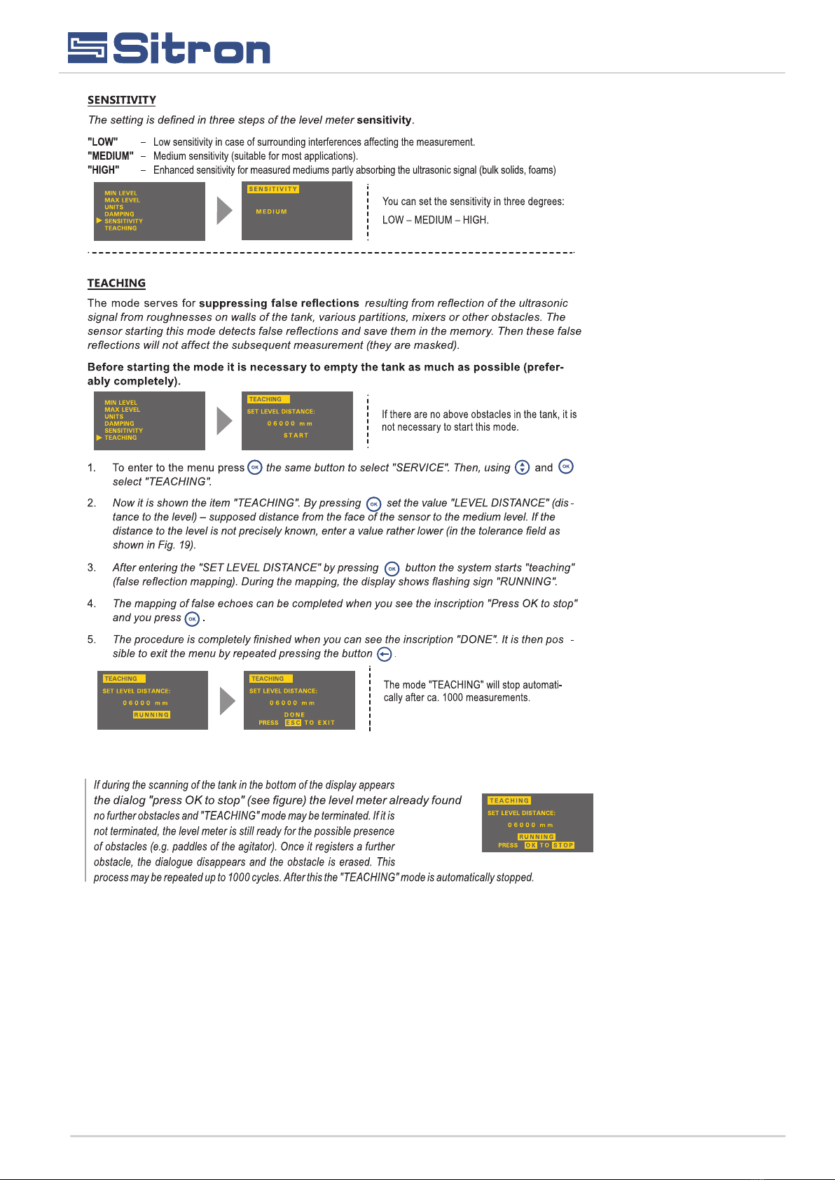
If the emitted ultrasonic signal of the level meter is affected by features, objects or obstructions (roughness on walls of the
tank, large welds, inner tank partitions, mixers etc.), it is necessary to map the false reflections by activating the mode
"TEACHING". In case of installed mixers, it is necessary to put the sensor in line with the mixer. (Fig.5 and 6).
Do not install the level meter directly in or above the filling point (Fig.7)
When measuring the level of bulk-solids, the measurement range is
reduced (due to absorption of ultrasonic waves by the bulk medium),
shortening the measuring range by up to 50% depending on the grain
material and size. We therefore recommend selecting a level meter with
greater range than the maximum measuring range for the application. It
is also appropriate to use a directional horn (see image 8), which
reduces the shortening of the measuring range, because enhances the
concentration of the acoustic energy while preserving the same beam
angle, and improves the sensitivity when receiving the reflected echo.
We recommend that Sitron is fully consulted before a model is selected.
Installation Manual

!
!
Fig. 9: Foam on the surface
Fig. 10: Moderately stirred
surface
Fig. 11: Intensely stirred surface
Obr. 12a: Short guide tube
installation
ventilation
holes
sleeves for
mounting
Obr. 12b: Total guide tube
installation
6
During filling, mixing and other processes, foam can develop on the
surface level of the measured liquid. The foam may considerably
absorb the ultrasonic signal which might cause malfunction or
inaccurate reading by the level meter.
(Fig.9). For such cases, it is necessary to set up " S E N S I T I V I T Y "
mode to "high" or contact Sitron for further consultation.
In case of a thin layer of foam, it is also possible to use the directional
horn for improving receipt of the reflected echo.
Scattering or attenuation of the ultrasonic signal can result if the surface
level has been moderately stirred or rippled (by a mixer, coming liquid
etc.). It can result in reduction of the measurement range or unreliable
function of the level meter (Fig.10).
Rotating mixer blades will cause surface agitation, which may result
in false reflections of the ultrasonic signal from the surface level and
unreliable operation of the level meter (Fig.13).(obr.11). For
a rippled or swirling level, you can use the directional
horn to eliminate scattering of the ultrasonic signal.
If the level sensor is mounted to bottlenecks and places with
barriers, or near uneven walls or the filling area, where the
transmission signal could be distorted, we recommend using a
guide tube (acoustic horn). The tube must be made from a single
material with a smooth inner surface (see image 12a, 12b). The
minimum tube diameter must have the dimension "b" according
to image 4 on page 5. After installing, you must perform the
procedure "TEACHING". We recommend consulting with the
Sitron on the construction of the guide tube.
Installation Manual
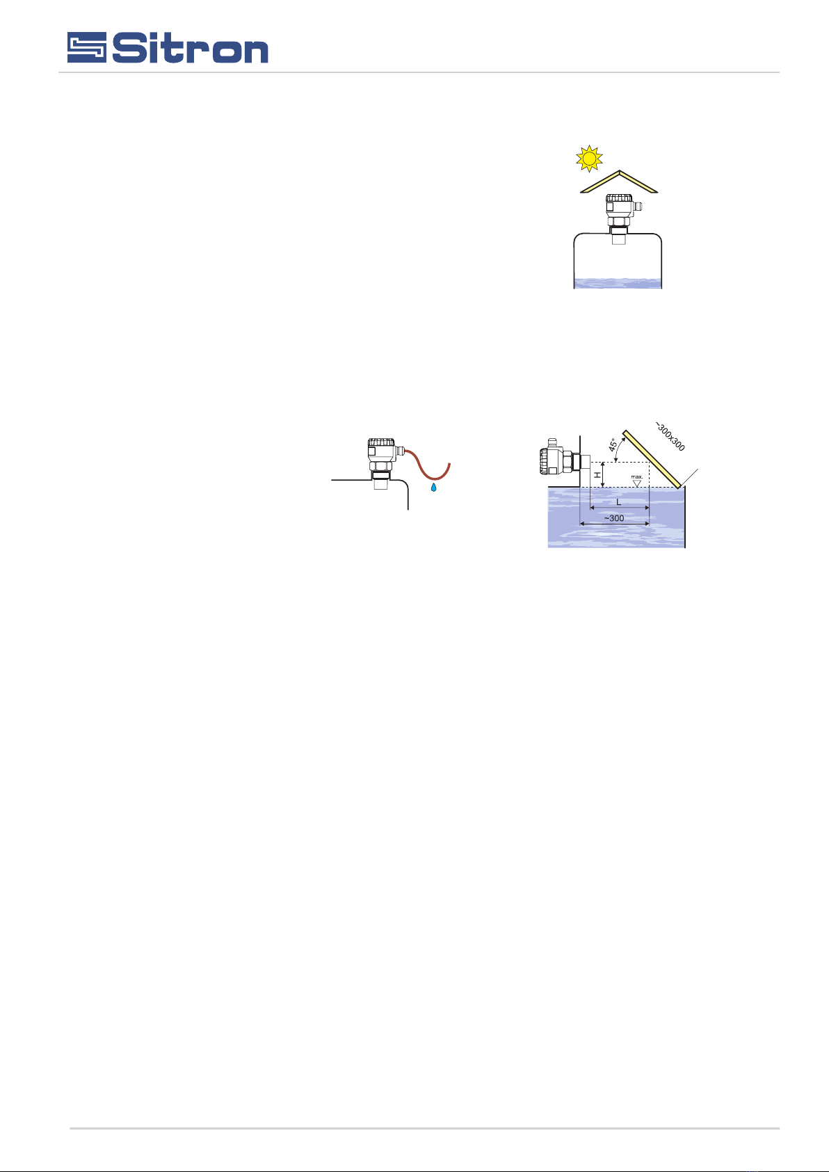
H + L = dead zone
Fig. 13: Solar radiation shielding
cover
Fig. 14: Prevention to avoid
intrusion of humidity
Fig. 15: Reflection board
7
The level meter must not be installed in places with direct
solar radiation and must be protected against the effects of local
weather.
If installation in places with direct solar radiation is inevitable, it is
necessary to mount a shielding cover above the level meter (Fig.
13).
It is suitable to run the cable under a cable bushing (obliquely down in
slack) according to Fig.14 to prevent penetration of humidity into the
housing. In this way, rain and condensing water can flow off freely.
The cable bushing and connector have to be sufficiently tightened to
prevent penetration of humidity.
To lower the minimum distance to the measured medium,
a reflection board made from solid, even and smooth material can
be installed to the level meter. Then the tank can be filled nearly up to
the maximum height. This solution is suitable for open tanks and
reservoirs (Fig. 15).
Installation Manual

8
display unit connector
Terminal block
metal clip
+A B IS
ON
GND
120
display unit connector
Terminal block
metal clip
120Ω switch
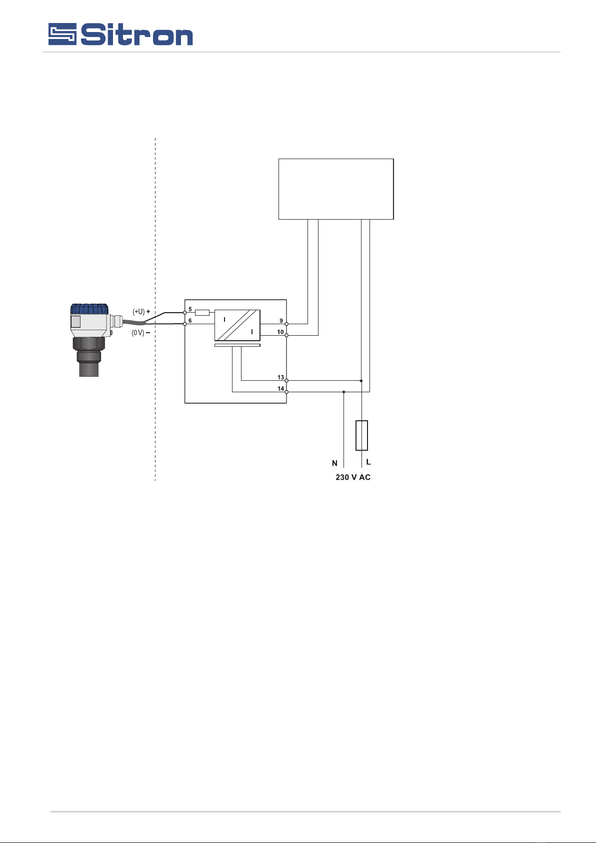
Electrical Connections
The level meter is connected to the power supply or PLC or other control (evaluating) devices with a suitable cable with
the outer diameter of 6 to 8mm using screw terminals located under the display module. The recommended cross
section of cores for the current version 2 x 0.5 / 0.75 mm² and for the version with Modbus communication 2 x 2 x
0.25mm² (twisted pair, shielded). Plus pole (+U) is connected to the terminal (+), minus pole (0 V) to the terminal (-) and
the shielding (only for shielded cables ) to the terminal ( ). Communication wires A and B of the line RS-485 ( for version
M - Modbus) are connected to the terminal A and B.
Inside view of screw terminals of the level meter with current
output SLU(02/06/10/20)-C
Wiring diagram of the level meter
with Modbus SLU(02/06/10/20)-M
Wiring diagram of the level meter with
current output SLU(02/06/10/20)-C
Electrical connection must be done in de-energized state!
The supply voltage source should preferably be realized as a stabilized power supply unit with safe voltage from 18 to 36 V
DC (18 to 30 V DC for X version), which can be a part of the evaluation or display device.
With case of strong electromagnetic interferences (EMI), parallel cable ducting with power lines, or when cable length
exceeds 30 m we recommended the use of shielded cables.
Inside view of screw terminals of the level meter with Modbus
SLU(02/06/10/20)-M
Procedure to connect the cable to the level meter:
1 - Unscrew the housing cover/ lid.
2 - Using your finger tips or finger nails, gently remove display by
clutching the upper edge of the display module.
3 - If you cannot grasp the module, you can use a small screwdriver.
Insert it as far as the seam allows so that it can be nudged upward as
you work your way around the display from several sides. This will
allow you to slightly lift the module.
4 - Release the cable outlet and thread the stripped supply cable in.
5 - Connect the cable to the screw terminals according to the diagram
in Fig.17 or 18. Firmly tighten the terminals and the cable outlet.
6 - If the level meter with Modbus is involved as a terminal for RS-485,
we recommend (to avoid reflections on the line) that the 120 ohms
switch is activated. This is done by moving the small lever of the switch
marked 120 ohms to the ON position. For level meters connected to
the line RS-485 as an intermediate device (i.e. Slave), the termination
resistors are not connected (switch remains off).
7- Insert the display module back into the head so that the connectors
is properly connected. Be carefull that the position is correct or the
terminal pins may be damaged.
8- Close the housing cover and then apply a PTFE or silicone tape seal
to the threaded connection of the level meter body.
Now the level meter can be installed into the tank and wired back to the
control unit or power supply. See safety not below.
Installation Manual
Fig. 17:
Fig. 18:

9
It is also necessary to design and take measures to reduce the effects of static electricity to a safe level
in the wiring. Installation in explosive atmospheres needs to be carried out in compliance with CSN EN
60079-14 (Electrical installations for explosive gaseous atmospheres - Part 14: Electrical installations
in dangerous areas other than mining) and possibly also in compliance with other standards relating
to the area concerned .
The supply voltage source should be preferably realized as a stabilized power supply unit with safe voltage from 18 to 36 V
DC (18 ÷ 30 V DC for Xi version), which may be part of the evaluation or display device. In case of strong electromagnetic
interference (EMI), parallel cable ducting with power lines, or when cable length exceeds 30 m, we recommend the use of
shielded cables.
Controller
SLU-
4...20mA
SLU-
Modbus
RS485 - Master
Connections for Level Meter with output 4 ... 20mA
Connection for Modbus Level Meter
Controller
Installation Manual
10
SIR420
Controller
SLU-C-X
Explosive area Non explosive area
Electrical connection for level meter in Classified Area
4...20mA
Galvanic separation of current signal from
transducer in explosive area
Installation Manual

11
Set up elements
Status Signalization
Installation Manual

12
Measurement Diagram
Manual de Instruções
1
2
3
100%
0%
MIN. LEVEL /
DISPLAY
MAX. LEVEL /
DISPLAY
1 - Dead zone or instrument erasure, (when level is above the dead zone a DEAD ZONE error message will show in the display
indicating that above this range the instrument will not measure) see (page 23) technical specifications to know the blind area of
the instrument.
2- Maximum distance or measuring distance to be respected for each transmitter model (eg SLU 02 measures up to 2 meters /
SLU06 measures up to 6 meters / SLU10 measures up to 10 meters / SLU20 measures up to 20 meters)
3 - Measuring range (Measuring range to be set on the transmitter in the parameters MIN. LEVEL 0% and MAX. LEVEL 100%
(with reference to the face of the transducer) and DISPLAY parameters by entering the value of the process that you want to show
in the display
Note: The measuring range to be configured must not be less than dead zone (1) and greater than the maximum ultrasound
measurement distance (2).
Reference (face of the transducer)

13
Basic configuration
Operation and Setting
Sitron
Installation Manual
14
Installation Manual
15
Installation Manual
16
Service settings
Installation Manual
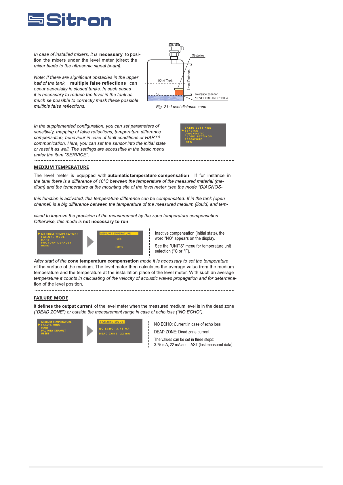
TICS’’), the measuring accuracy will be reduced by around 1% of the set range. If
perature in the place of installation of the SLU (see mode, DIAGNOSTICS), it is ad-
17
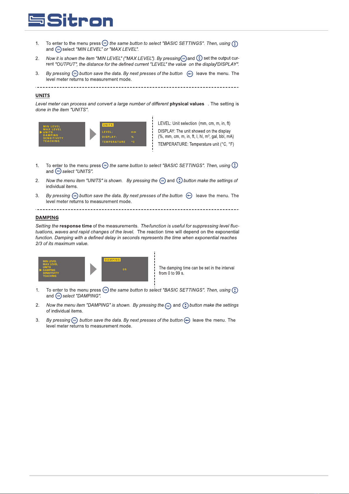
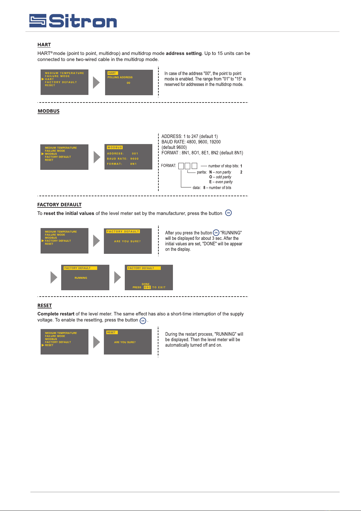
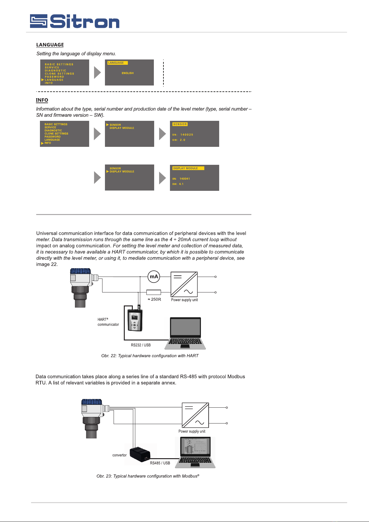
This item is part of a menu with Modbus output level meter SLU-M. Modbus mode is intended
for the settings of the level Modbus addresses, baud rate and parity settings.
Installation Manual

18
Additional functions
Installation Manual
of level meter SLU body
configuration into the display module and back.
19
Installation Manual
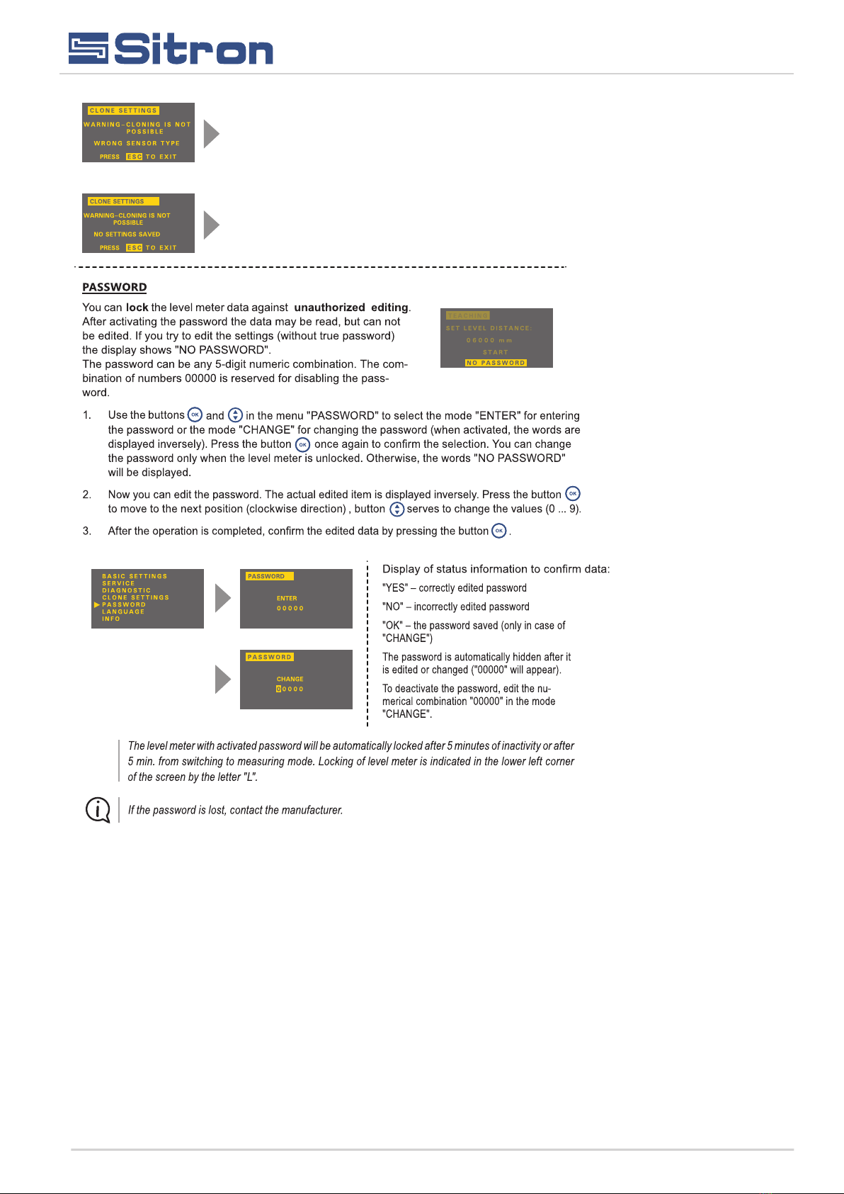
Incompatible type of level meter. Transfer of the settings can be realized
only with the same type of level meter (e.g. SLU-02 with SLU02, SLU-06
with SLU06) and with the firmware version 2.0 and later
The data set is not stored into the display module. The transfer can not
be done. its necessary to repeat the procedure of the copying the
settings in the mode CLONE SETTINGS.
20
Protocol HART
SLU
Protocol Modbus
SLU-M
SMC-485
Installation Manual
SLU-XX
SLU
This manual suits for next models
4
Table of contents
Popular Measuring Instrument manuals by other brands


BEKA
BEKA FOUNDATION BA444NDF-F manual

Spectronics
Spectronics Spectroline DMXA Series Operator's manual

Trotec
Trotec BX50 MID operating manual

KROHNE
KROHNE OPTISONIC 7300 Supplementary instructions

AEMC instruments
AEMC instruments DIGITAL FLEXPROBE 400D-6 user manual

Oval
Oval ALTI mass Series instructions