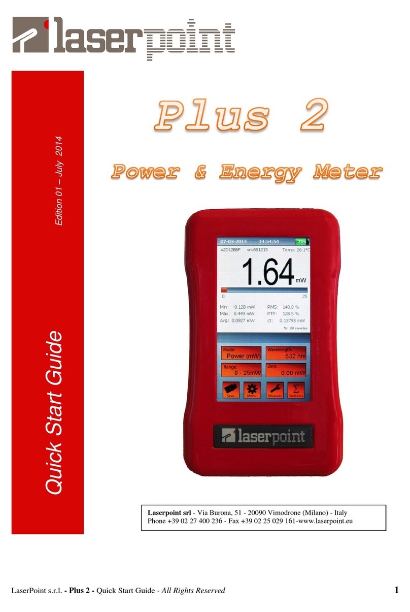
LaserPoint Plus2 User manual

LaserPoint s.r.l.- Plus2 Power & Energy Meter Instruction Manual - All Rights Reserved 1
Instruction Manual
Edition 02 –July 2017
P
PL
LU
US
S2
2
P
Po
ow
we
er
r
&
&
E
En
ne
er
rg
gy
y
M
Me
et
te
er
r
M
Me
et
te
er
r
LaserPoint srl - Via Burona, 51 - 20090 Vimodrone (Milano) - Italy
Phone +39 02 27 400 236 - Fax +39 02 25 029 161-www.laserpoint.eu

LaserPoint s.r.l.- Plus2 Power & Energy Meter Instruction Manual - All Rights Reserved 2
Plus 2Laser Power & Energy Meter
User’s Manual
Index
1. Safety notes ..................................................................................................................................3
2. LaserPoint intelligent connectors.................................................................................................3
3. Introduction to Plus 2Power/Energy Meter.................................................................................3
4. Head compatibility –important information................................................................................5
5. Switching Plus2 On and Off-Quick start......................................................................................6
6. The touch screen display..............................................................................................................6
7. Instrument Function Keys: Menu key..........................................................................................7
8. Instrument Function Keys: Range key.........................................................................................8
9. Instrument Function Keys: Zero key............................................................................................9
10. Instrument Function Keys: Wavelength key..............................................................................10
11. Instrument Function Keys: Measure key ...................................................................................11
12. Instrument Function Keys: Mode key…………………………………………………………13
13. Instrument Function Keys: Statistics key...................................................................................15
14. Instrument Function Keys: Save key……………………………………..……………………16
15 Instrument Alarms………..……………………………………………………………………18
16 Firmware updates .......................................................................................................................19
17 Specifications .............................................................................................................................20
18 Warranty.....................................................................................................................................21
19 Limited Liability.........................................................................................................................21
20 Declaration of Conformity .........................................................................................................22
21 Compliance to RoHS Directive (RoHS 2002/95/EC)...............................................................23
22 European Union WEEE Directive (WEEE 2002/96/EC)...........................................................23

LaserPoint s.r.l.- Plus2 Power & Energy Meter Instruction Manual - All Rights Reserved 3
1. Safety notes
Before operating this instrument, carefully review the following safety information to avoid personal injury and
prevent damage to this instrument or any sensor head connected to it. This instrument does not contain any user-
serviceable parts.
The measuring as well as the use of lasers is potentially dangerous. This instrument may operate over
wavelengths including non-visible laser radiations.
Proper operating practice in accordance with laser manufacturer’s recommendations is crucial; to ensure
correct operating procedures, consult the laser manufacturer and your laser safety officer.
Eyewear and other personal protective equipment must be used in compliance with applicable laws and
safety regulations.
Operate this instrument only within the specified range of operating conditions (refer to chapter 17 for
environmental and operating conditions).
Do not operate this instrument in critical medical environments, in wet or damp conditions or in an
explosive atmosphere.
Do not operate this instrument if in suspect of damage or failures. Refer about damaged equipment to
LaserPoint for qualified service inspection.
2. LaserPoint intelligent connectors
All LaserPoint sensor heads feature an intelligent connector where the relevant data and information pertaining
the sensor head are stored in a built in memory. The head model, its identification number, the head full scale, the
calibration wavelength(s), the head sensitivity spectrum vs wavelength and the head calibration date are all stored
in the connector memory.
In general, detectors feature different sensitivity values at different wavelengths depending on the detector nature
(this is especially true for those based on semiconductor devices), so it is important to account for this when
measuring power and energy values. All LaserPoint sensor heads are calibrated up to the rated power/energy head
full scale at least at one desired wavelength. All sensor heads are now characterised over a large wavelength range
too using a low power broadband source and the obtained sensitivity spectrum is loaded into the smart connector
memory as a table of discrete sensitivity wavelength dependent data.
All standard LaserPoint thermopile and semiconductor sensor heads are equipped with a DB 15 pin intelligent
connector.
3. Introduction to Plus 2Power/Energy Meter
Plus 2 is an ergonomic micro computer based instrument with a high brightness, 4.3”- high resolution (480 x 272)
TFT LC touch screen display. It is powered by a Li-Pol rechargeable battery. The battery recharge is carried out
by connecting its USB connector cable to a PC or to the supplied line charger/power supply USB port.
Plus 2 keeps in memory all sensor head data and settings up to ten different heads that have been connected to the
instrument; a further head connection to the instrument, displaces the first head data from the intelligent connector
memory and records the last connected head settings. Plus 2 features a high speed algorithm suitable to accelerate
the response and the recovery of thermopile sensor head signals.
The colour touch screen display on the front side of the instrument is the actual user interface; it can be operated
by simple and very intuitive actions. It allows the user to easily interact with the instrument and quickly set it up
for measurements. A stainless steel stand gives the instrument an optimum tilt to offer the best screen view when
the instrument is used on a laboratory table.

LaserPoint s.r.l.- Plus2 Power & Energy Meter Instruction Manual - All Rights Reserved 4
Fig.1 Front view of Plus 2 power/energy meter
Instrument switches and ports- The instrument TOP side, shown in Fig. 2, hosts the white On/Off switch, the
external power supply cable USB plug and one DB 15 pin connector as the input port for all LaserPoint
power/energy head signals.
Fig. 2 Top view of Plus 2 power/energy meter
Ext
Power
supply
On-Off
switch
15 Pin
connector
socket DB15

LaserPoint s.r.l.- Plus2 Power & Energy Meter Instruction Manual - All Rights Reserved 5
The instrument left side hosts one USB port for connecting a memory key suitable to download selected data; the
actual measurement signal voltage (2 V full scale) can be extracted by the analogue output port (Fig.3) placed at
the instrument right side.
a) b)
Fig. 3 Side views of Plus 2
a) instrument left side (USB data port)
b) instrument right side (Analogue output port)
Instrument battery and power supply- The instrument is powered by one 3,7 V rechargeable Li-Pol battery or
by its line power supply that acts also as battery charger. LaserPoint recommend to use ONLY the power supply-
battery charger supplied with the instrument.
Touch Screen Display- Figure 4 shows the touch screen display; in its upper right corner the display hosts an
icon showing which type of power source is used.. A green battery icon with an associated figure indicating its
charge level in percentage of its full charge (in 25% unit steps) shows the instrument is powered by its
rechargeable battery. When the battery is about to be exhausted the green icon converts to a red vertical bar
associated with a small white plug. When the instrument is plugged in its line power supply the icon converts in a
white plug icon.
The instrument can be operated up to 9 hours by a fully charged battery.
The battery complete recharge takes approximately 7-8 hours if the instrument is not working and may take up to
20 hours if it is being used.
4. Head compatibility –important information
All LaserPoint heads are compatible with Plus 2 meter, but the stored information in the head EEPROM depends
on the head manufacturing period and on the type of read out unit that was planned to be used in connection with
such a head. The intelligent connector of the heads supplied together previously issued read out units like Plus,
4Pi and PC-Link meters contain more limited information especially regarding the calibration wavelengths and
wavelength ranges; this may limit to exploit the full information potential Plus 2 read out unit can provide if used
with a recently manufactured head. Therefore, in order to exploit the full potential offered by Plus 2 meter,
LaserPoint recommend the upgrade of all the sensor heads supplied before the issue of Plus 2 meter at factory.
Contact LaserPoint to check if a previously supplied head needs to be upgraded for its use with Plus 2 read out
unit.

LaserPoint s.r.l.- Plus2 Power & Energy Meter Instruction Manual - All Rights Reserved 6
5. Switching Plus 2 ON and OFF - Quick start
To start a power measurement in a quick easy way, simply follow this list of actions:
-Connect a LaserPoint head to Plus 2 by plugging the head connector into the instrument 15 pin socket
(fig.2) and properly tighten the connector side screws.
-Switch Plus 2 on by keeping the On/Off switch (fig.2) pressed for few seconds until the instrument
display lights on. Should the display show “NO HEAD”, check the connector is properly plugged in the
instrument 15 pin socket.
-Check the desired laser wavelength value is displayed in the Wavelength key (Fig.4 ( g) )
-Start the measurement cycle by placing the active area of the detector head in front of the laser source.
Carefully ensure the laser beam hits the active sensor area only to avoid possible head damage and
misleading power measurements. The measured laser beam power value is soon displayed on the
instrument screen.
-To switch the instrument off press the ON/OFF switch until the display goes off.
6. The touch screen display
After Plus 2 has been switched on, its multifunctional touch screen becomes the actual interactive interface
between the user and the instrument.
Fig.4 shows an image of Plus 2 meter touch screen; its display is split in two main parts: its upper part is
dedicated to reports the measurement related information and is the read out only part of the touch screen display.
The lower part is the actual interactive area of the instrument and is filled with the touch screen keys dedicated to
the instrument and measurement settings.
After touching one of the screen keys, a window as first interaction user-instrument element appears on the
display. The window generally offers two main interactive tools: a dialogue box with two or more options or a
digital keyboard, depending on what kind of input the instrument needs. These two kind of tools allow the user to
select an option or generate and enter a numerical input. Both parts of the display have horizontal sections
dedicated to specific information or interactive actions as described below:
a) Date - Time - Battery/line icon
b) Sensor Head model, serial number and operating
sensor temperature (°C)
c) 4 digits display and measured entity units
d) Analogue bar graph normalized to the selected full
scale
e) Sample counts and time regarding the statistical
elaboration, if selected. Warnings, alarms and alert
messages are also displayed in this section
f) Data logging duration and visualisation of specific
measurement settings
g) Four function keys with entity value visual
information: Mode, Wavelength, Range and Zero
h) Four function keys: Save, Menu, Measure and
Statistics offer quick access to specific interactive
windows.
Fig. 4 The touch screen display
a
b
c
d
e
f
g
h

LaserPoint s.r.l.- Plus2 Power & Energy Meter Instruction Manual - All Rights Reserved 7
7. Instrument Function Keys: Menu key
MENU key allows access to the main instrument settings. Touching this key opens the Menu window as
shown in Fig. 5a. This window features eight lines showing the information about:
Date: sets the date in the dd/mm/yy format.
Time: sets the time in the hour/min/sec format and the hour is displayed in the 0-24 h format.
Language: instrument language ( english is the only available language in this instrument release, other
languages will be available in the next firmware update).
Colour instrument background colour (other background colours will be available in the next firmware update).
Fig. 5a The Menu Window Fig. 5b The Digital Keyboard Window
Display off: For energy saving purposes it is possible to set a time of instrument inactivity after which the
display is automatically switched off; a faint mobile “stand-by”notice will advise the user of the idle instrument
state. Selecting ON/OFF activate/deactivate this option; if ON has been selected the display off time can be set
from 1 to 30 minutes. When Plus2 is in stand-by mode, touch the screen in any place to recover immediately the
instrument display operation.
Auto off: Time of instrument inactivity after which the whole instrument switches off; selecting ON/OFF
activate/deactivate this feature; if ON has been selected, Auto off time can be set from 1 to 600 minutes.

LaserPoint s.r.l.- Plus2 Power & Energy Meter Instruction Manual - All Rights Reserved 8
Note: both Auto off and Display off features are active only when Plus 2 is powered by its battery.
When Plus 2 is plugged in a power line both the instrument and its display remain on regardless to Auto off and
Display off set values.
Factory restore: this function resets all measurement, statistics and wavelength settings back to the ex- factory
conditions. Activating this option erases the information regarding all sensor heads previously connected to
Plus 2 meter.
90° Full Screen: this option switches the screen content to a 90° rotated full screen high visibility and high
contrast display and presently works in Power Mode only. When this display mode is activated the measured
power value and its related units are shown only as shown in Fig.6. Click the “X” screen button to return to the
main operating display configuration.
Each of the above listed parameters has a number of small boxes ranging from 1 to 3 placed at its right side in
Menu window. Some boxes have options to validate or select, some need a parameter value to be entered. To
change or enter a parameter value touch the pertaining parameter box; a digital keyboard as shown in Fig. 5b
appears and allows the setting of the desired value to be entered in the touched box.
Fig. 6 Image of 90° Full Screen activated option
8. Instrument Function Keys: Range Key
This key allows the measurement full scale (or range) to be adjusted according to user’s needs. The
selectable ranges depend on the sensor head type and usually are:
-Absolute Maximum Sensor Handling Power/Energy value
-100% of Sensor Full scale value
-10% of Sensor Full scale value
-Automatic range (only in Power Mode)
To select a desired measurement range touch the Range key and keep it pressed to scroll
the available options; release the key when the desired option is displayed in the key area.

LaserPoint s.r.l.- Plus2 Power & Energy Meter Instruction Manual - All Rights Reserved 9
9. Instrument Function Keys: Zero key
Zero function key helps the user defining the optical zero of the sensor head as well as the electrical zero by
resetting the instrument ADC.
Zero function key may also be used to introduce a desired offset to a series of measurements.
All meter adjustments are carried out by Plus 2 firmware, however LaserPoint recommend to reset Plus 2 Meter
every time a new sensor head is being plugged in.
Both head optical resetting and ADC electrical resetting have to be accomplished manually by using Zero key
and following few simple steps as indicated below:
Important notice: before starting an electrical resetting sequence, ensure the sensor head is in thermal
equilibrium with the environment that no laser radiation accidentally hit the sensor not to introduce an unwanted
offset level. The head shall be properly blinded in the case of high sensitivity heads.
-To optically reset a head briefly touch Zero key .
-To reset the ADC keep Zero key pressed until the window shown in Fig. 7 appears on the screen in the
display segment e) as described in Fig. 4
Fig. 7 ADC resetting request window
-Touch Yes and wait few seconds while the screen shows the notice “Wait for zeroing” (Fig. 8a).
When the ADC has been finally reset the notice “Zeroing Completed” (Fig. 8b) appears on the
display and the meter is ready for use again.
Fig. 8a “ADC resetting in progress” notice Fig. 8b “ADC reset” notice
Offset: the introduction of an offset level in a measurement may be useful in certain cases. Plus 2 can
easily introduce an offset power value and to do it, briefly touch Zero key and the currently measured
power level is accounted by Plus 2 and introduced as the offset power level. When an offset has been
introduced, its value and units are shown in the Zero key area. An additional yellow spot appears in the

LaserPoint s.r.l.- Plus2 Power & Energy Meter Instruction Manual - All Rights Reserved 10
upper right corner of the key area to highlight that an offset has been introduced. To
cancel the offset level, briefly touch Zero key again.
10. Instrument Function Keys: Wavelength key
In general detectors exhibit different sensitivity values versus different wavelengths depending on the detector
nature; detectors based on semiconductor devices may show very important variations of their sensitivity against
wavelength, so it is important to account for this effect when measuring a laser beam power or energy.
All LaserPoint sensor heads are calibrated up to the rated power/energy full scale at least at one desired
wavelength and can optionally be calibrated at many other wavelengths between 200nm and 2100nm and at
2940nm (Er-YAG laser) and 10600nm (CO2 laser); this information is stored in the head intelligent connector
memory and is read by the instrument upon connection of the head to it. Furthermore LaserPoint heads are
characterised over a wider wavelength range using a low power broad band optical source; the broad band
thermal heads are all characterised between 200nm and 2100nm; photodiode heads are characterised up to the
detector cut-off wavelength. The obtained sensitivity spectrum is loaded into the head smart connector memory
as a table of meaningful discrete wavelength dependent sensitivity values. If the desired wavelength does not fit
one of the loaded sensitivity points, the instrument calculates the detector sensitivity value at the desired
wavelength by an interpolation algorithm.
Fig. 9a The Wavelength Window (example) Fig. 9b The Digital Keyboard Window
To set a measurement wavelength touch the Wavelength key to open the wavelength dialogue
window shown in Fig. 9a. Select a wavelength from the list shown at the left hand side of the window or
touch an “edit nm” box at the right hand side of the window to input a specific wavelength not shown in
existing list.
Touching one of the “edit nm” boxes makes a digital keyboard to pop up as shown in Fig. 9b and allow
the wavelength selection. The desired wavelength value in nanometer units must be comprised in the

LaserPoint s.r.l.- Plus2 Power & Energy Meter Instruction Manual - All Rights Reserved 11
specific head wavelength range shown at the top of the wavelength selection window. Touch the “OK”
button to enter the selected wavelength; its value is then shown in the box with a green background in
the left hand side list. Touch the green box to be confirm the choice.
Note: The available wavelengths and editable wavelength range depend on each sensor head characteristics and
calibration. In any case beyond 2100nm the only selectable wavelengths are 2940nm and 10600nm if the sensor
head has been requested to be calibrated at these wavelengths.
11. Instrument Function Keys: Measure key
Measure key allows to account for specific conditions of measurement and set parameters like the sensor
signal acceleration, gain and averaging option. When in Power Mode (see paragraph 12) touching this key opens
the “Measure settings” windows allowing the view and setting of the above parameters; this window allows also
to specify the laser beam shape and its dimensions enabling the calculation of the laser beam power or energy
density and to change the DAC calibration value if necessary to enhance the analogue output sensitivity. The
instrument last calibration date is also shown at the bottom of the window. The “Measure Settings”window for
Energy Mode is somehow different and is described in the following chapter Mode Key.
“Measure Settings” window (Fig.10) opens by touching Measure key .
The Acceleration factor is a useful tool when using large and intrinsically slow thermal heads whose typical
response time can reach several seconds. When this option is activated an instrument algorithm accelerate the
signal response in order to speed the instrument response up. LaserPoint recommend to keep this option always
selected when using thermopile sensor heads, unless the laser output is instable or the detected power signal is
weak and noisy.
The selection/de-selection of Acceleration option is straightforward and is accomplished by touching the small
box at the right of this parameter writing.
Fig. 10 Measure Settings Window (Power Mode)
The Gain factor (factory default setting = 1) is a useful tool especially when measurements are carried out in
complex optical systems.

LaserPoint s.r.l.- Plus2 Power & Energy Meter Instruction Manual - All Rights Reserved 12
Typically this tool is particularly useful to normalise a measurement or when the measurement is taken out of a
complex optical systems where, for instance, a beam splitter is used to extract a fraction of an optical signal; in
most cases the beam splitter has two output optical ports with significantly different splitting ratios to allow the
laser beam to exit the main port of this component almost unaltered and enabling the monitoring of the beam
power or energy by measuring the small fraction of the beam at the monitoring port output.
If the power meter is connected to a sensor head placed at the monitoring port, a gain factor can be set to take into
account the device optical splitting ratio by adjusting Gain factor and make the instrument show a power reading
as though the sensor head were placed in front of the original laser beam. The selection of Gain option need the
input of a number by means of the digital keyboard popping up upon touching the small box at the right of this
parameter writing; the parameter input is accomplished in a similar way as described in the previous paragraph 10
for the measurement wavelength selection.
The Average factor is a useful tool when the signal is low and noisy and allows a cleaner signal read out; its
settable value represents the time period during which the head signal averaging occurs.
Average value can be set from 0.1 sec to 99 sec and when a value greater than zero has been entered a yellow
frame borders Measure key and an “Avg.” notice appears just in the right side of the display segment f) ( see Fig.
4).
Measure function key allows also to set and take into account the laser beam Shape and dimensions; this feature
is particularly useful when irradiance and/or fluence are important information to the user like in the case of
certain medical protocols that have to guarantee the deposit a certain dose of photonic power or energy per unit
surface.
The measurement of Irradiance (power density) or Fluence (energy density) requires the selection of a laser beam
Shape and the definition of the beam area. This selection has to be done among the following options: none,
circular, rectangular.
If none option is being selected, the integral beam power or energy will be measured and the display keeps on
showing the measurement power or energy values in W or J or their sub-units.
If the circular beam shape is being selected the Radius box is activated and upon touching it the beam radius in
millimeters can be entered after touching the relative box by the already described digital keyboard.
If the rectangular beam shape is being selected the Width x Height boxes are activated and their relative
dimensions in millimeters have to be entered by the usual digital keyboard.
In both cases of circular and rectangular beam shape selection, the Irradiance measurement values are expressed
in W/cm2 units or sub-units and the Fluence measurement values are expressed in J/cm2 units or sub-units. The
beam area in square centimeters is calculated by the instrument and shown in the box aside the Area writing.
To de-activate Irradiance/Fluence mode, select none for Shape in the “Measure Settings” window.
The last two parameters reported at the bottom of “Measure Settings” window are DAC and Last Calib.
DAC stands for the analogue output sensitivity and is stored in the head intelligent connector memory. Its value
is factory set and is expressed in mV/W. In certain cases it might be convenient to expand the sensitivity of the
analogue output signal and this coefficient can be changed by the user by means of the digital keyboard popping
up after touching the small box aside DAC writing.
Last Calib. Indicates the instrument last calibration date and is for information only.
Note: in the case Energy Mode has been selected, “Measure Settings” window shows some parameters that are
specific of pulse energy measurements, hence further information pertaining to energy measurement settings is
reported in Mode key chapter 12.

LaserPoint s.r.l.- Plus2 Power & Energy Meter Instruction Manual - All Rights Reserved 13
12. Instrument Function Keys: Mode key
Mode key is basically a switch allowing to change the instrument settings in order to make a laser
beam power measurement or energy measurement.
Selecting a power beam measurement or energy measurement is quite easy: just touch Mode key and
switch from power to energy mode or viceversa.
The measurement units are than changed according to the mode selected and to the used sensor head
type and function (power or energy) range. To recover the original mode just touch Mode key again.
Upon switching from power to energy mode the instrument display may report the message “Zeroing is
necessary” as shown below in Fig.11; in this case press “OK” and follow the procedure already
described in Zero key paragraph 9.
Fig. 11 Resetting request notice in Energy Mode
Fig. 12 Measure Settings Window (Power Mode)
In energy mode both single pulse energy detection and burst pulse (multiple pulses) energy detection is possible.
Important notice: operating Plus2 meter in an energy mode however implies that the measurement
signal shall exceed a pre-set energy threshold. The instrument has been designed to measure the energy

LaserPoint s.r.l.- Plus2 Power & Energy Meter Instruction Manual - All Rights Reserved 14
of pulses above a preset energy threshold to avoid unwanted contribution of thermal noise or
background radiation to the measured pulse energy.
To set an Energy Threshold ensure the instrument is already in Energy Mode, then touch Measure
key to open the “Measure Settings”window.
Briefly touch Start threshold box and scroll to select the threshold among three possible options:
“high”, ”med” or “low” by short touches on the box. The instrument factory setting for energy
threshold is always "med”, i.e threshold medium level.
A couple of hints to adjust the threshold level are given below.
-If the head intrinsic noise is high enough to trigger the meter, set the threshold to "high”.
-If the pulse energy is weak and triggering the meter might be critical, set the threshold to "low."
After adjusting the threshold level, reset the instrument in the case the “Zero notice” appears as shown in
Fig. 11.
Set the energy range manually (as described for power in Chapter 8). In energy mode only manual range setting
is allowed.
A green spot at the upper right side of the display shows the instrument is ready to carry out a pulse or a burst
energy measurement.
Fig. 13 Energy Mode display when ready for a pulse or burst detection
Shoot the laser pulse or burst and during the shot the display shows a window with the “Acquisition” notice
(Fig. 14a) and the green spot at the upper right side of the display turns red.
When using a thermopile sensor head the “Acquisition” time usually ranges from 1 to 5 seconds depending on
the used sensor head and if a single pulse or multiple pulse energy has to be detected.

LaserPoint s.r.l.- Plus2 Power & Energy Meter Instruction Manual - All Rights Reserved 15
14a “Energy measurement in progress” notice Fig. 14b “Energy measurement over” display aspect
As soon as the pulse energy detection is over, the energy measured value is displayed and the spot turns
green again indicating the meter is ready for a further pulse energy measurement (Fig 14b).
Note: The correct measurement of the integral energy of a burst of two or more pulses carried out by a
thermopile head requires that the pulse repetition rate is greater than 1Hz to avoid incurring in possible
individual pulse energy detection.
13. Instrument Function Keys: Statistics key
Statistics key enables the statistical elaboration of the measured data and its settings.
When the instrument operates in Power Mode four statistics elaboration options are possible:
-Off: no statistics.
-Continuous: the data elaboration is made on a continuous data collection basis.
-Repeated: the data are repeatedly collected and elaborated within a user’s defined time period.
-Single: the data are collected and elaborated once only within a user’s defined time period.
Touch the Statistics key to open the “Statistics” windows (Fig. 15) and access these four options displayed as
four rectangular interactive boxes in the window.
Upon touching a box its background becomes green indicating its selection.
“Off” or “Continuous” options need no more instructions.
“Repeated” or “Single” options require the definition of a time period that limits the statistical data collection and
elaboration, hence after selecting one of these two options the needed period information in hours, minute and/or
seconds has to be entered in the three small rectangular boxes just below these option keys.
Upon touching each time-information boxes the usual digital keyboard pops up allowing the desired time setting.
To enter the newly generated option and where it applies its time entity touch “Reset”box.
To exit “Statistics” window without changing any selection touch the “X” cross at the upper right corner of the
window.

LaserPoint s.r.l.- Plus2 Power & Energy Meter Instruction Manual - All Rights Reserved 16
Fig. 15 The “Statistics” Window (Power measurement)
When the instrument operates in Energy Mode two statistics options only are possible: Off and Continuous.
Therefore “Repeated” and “Single” option and period setting boxes in “Statistics” window are inactive.
14.
Instrument Function Keys: Save key
Save key allows to plan the data collection mode and save the measured and/or the statistics elaboration
data in a USB key by means of “Data Logging” window option selection.
Two data acquisition mode options are possible:
Manual: the data acquisition starts and stops by means of manual commands.
Timed: the data acquisition occurs automatically within a pre-defined time.
Touching Save key opens “Data Logging and Acquisition ” window (Fig 16) that is the main tool to define
which data (measured values and/or statistics) have to be acquired and saved as well as the acquisition mode
option (Manual or Timed).

LaserPoint s.r.l.- Plus2 Power & Energy Meter Instruction Manual - All Rights Reserved 17
First plug a USB key in the instrument USB port (Fig 3a).
Depending on the USB flash memory speed, the USB drive might not be ready yet and in this case the ”USB not
ready” notice (Fig. 17) is displayed. Wait few seconds until this notice disappears.
Select the desired data to be saved by just ticking the small box at the right side of the writings Values and/or
Statistics. Touch the small box at the right side of Sample rate to make the usual digital keyboard appear and set
the desired sample rate between 0.5 and 99 seconds.
Important note: If “Continuous”statistics has been selected, the sample rate value refers to both measurement
Values and Statistics data.
If “Single”or “Repeated”statistics have been selected the sample rate refers to measurement data only, because
in these two cases Statistics data are saved each time they are refreshed.
Should the data acquisition be started and stopped manually select Manual acq. by ticking the small box at this
writing right side.
Should the data acquisition be automatically stopped after a predetermined period of time select Timed acq. by
first de-selecting Manual acq. box, if ticked, and entering the desired acquisition time value in hours and/or
minutes.
Touch “OK” button to input all the selections and exit “Data Logging and Acquisition” window.
Fig. 16 The “Data Logging and Acquisition” Window
Fig. 17 Slow USB key notice
After all the mentioned selection actions have been completed the instrument is ready to start the measurements
and save the measured and/or statistics data.

LaserPoint s.r.l.- Plus2 Power & Energy Meter Instruction Manual - All Rights Reserved 18
At this moment Save key converts in a “Start” button . Touch it to start the data acquisition and their
logging; in these conditions the lower part of the instrument display gets the aspect shown in Fig. 18a.
During data acquisition and logging the lower part of the instrument display assumes the aspect shown in Fig.
18b.
After the data acquisition has started, the “Start” button converts in a “Stop”button allowing the user to stop
the data acquisition if Manual acquisition mode has been selected or to stop the data acquisition for any reason.
During the data acquisition the display segment f) in Fig. 4 shows a timer in its upper left part. The time shown by
this timer is the elapsed time in the case a Manual acquisition mode has been selected and the residual time in the
case a Timed acquisition mode has been selected.
Fig. 18a The “Acquisition ready”display image Fig. 18b The “Data Logging”display image
The logged data are then saved in an automatically generated folder in the USB memory named according
the following format:
X:\PLUS2\head serial number
The measured Values and Statistics data are saved in separate files contained in the previously described
folder and respectively named according the following formats:
DATA_nnn.txt and STAT_nnn.txt
15. Instrument alarms
This instrument displays two types of alarms: the head excess temperature alarm and measurement overflow
alarm. The instrument issues a warning message that appears on the display and remains up until the cause of the
alarm is being removed.
Overflow Alarm: This alarm appears when the signal detected by the instrument exceeds the instantaneous
maximum power the sensor head can bear or the manually selected measurement range has been overcome.
Temperature Alarm: This alarm is active for thermopile sensor heads and it appears when the sensor head
temperature exceeds its specified safety limit (typically 80°C).

LaserPoint s.r.l.- Plus2 Power & Energy Meter Instruction Manual - All Rights Reserved 19
16. Firmware updates
Among its innovating features Plus 2 allows firmware updates to be accomplished at customer’s site using a
simple and quick (less than 2 min) procedure. The firmware update file will be provided by LaserPoint via an e-
mail message attachment.
To update the instrument firmware simply follow the instruction steps given below:
-Switch the instrument ON and plug the instrument to its external power supply.
-Copy the firmware update file in a free USB drive
-Plug the USB drive in the instrument USB port.
-After 10 seconds the display will show the image of Fig 19a, touch “Yes” to proceed.
-During the FW update file downloading Fig. 19b is shown and a moving bar indicates the file
downloading progress .
Fig. 19a FW update? Fig. 19b FW downloading… Fig. 19c FW downloading done
-Upon FW update file downloading is completed Fig. 19c image is shown on the display.
-Read carefully the instructions shown in the window before touching “Ok” key to start the instrument
switch off.
-After few seconds the instrument switches off; remove the USB drive and then push the instrument
ON/OFF button and keep it pressed until the display turns on again (this step takes about 10 sec).
-Upon the instrument switch on its FW is been updated and Plus 2 meter is now ready for new
measurements.

LaserPoint s.r.l.- Plus2 Power & Energy Meter Instruction Manual - All Rights Reserved 20
17. Instrument specifications
Detector Compatibility Thermopile, Photodiode and OEM LaserPoint Sensor Heads
Input Ranges 7 mV –700mV full scale, in 9 ranges
A to D Sampling rate 64 Hz
A to D Resolution 23 bit ADC resolution, 16bit processing resolution
Electrical accuracy ± 0.5%
Electrical Input Noise 500nV
Input Offset Voltage drift -4nV/°C (typical)
Dynamic Range 8 decades
Analogue Output 0.025 - 2 Volt, with 16-bit (0.0015% resolution.)
Analogue Output Accuracy ±0.1% ±2mV relative to display
Display 4.3" TFT LCD high brightness, 480 x 272 resolution, resistive touch
panel 96 x 55 mm HxW
Display Digit Height 15mm Standard Operation - 25mm Full Screen Operation
Bargraph Segments 250 pixel width
Instrument Dimensions 170 x 100 x 36-50 (mm) HxWxD
Weight 380 g
Battery Built in rechargeable Li-Pol. 3.7V 3700mAh
Battery run time > 9 hours in normal operation
> 15 hours in stand-by display mode
Battery charge time 7-8 hours not working
15-20 hours working
Power Supply- Battery Charger Input 100/240Vac 50/60Hz Out 5Vdc 1A, (Plus 2 can be charged
through a PC USB port).
Charge Current 0.5A
Operating Temperature Range +5° to +40°C
Storage Temperature Range -20° to 70°C
Max relative humidity 70%
International Regulations , RoHS compliant.
Table of contents
Other LaserPoint Measuring Instrument manuals
Popular Measuring Instrument manuals by other brands

Orbit Merret
Orbit Merret OMM 37 manual

Eastron
Eastron SDM630-EV user manual

McCrometer
McCrometer FPI Mag 394E Installation, operation and maintenance manual

Hanna Instruments
Hanna Instruments HI97726 instruction manual

Rohde & Schwarz
Rohde & Schwarz FSEA20 operating manual

Agilent Technologies
Agilent Technologies EPM-P Series Battery Operation