Sitron SP10 User manual

USER MANUAL
Installation, Operation and Maintenance Manual
Pressure Transmitters
Series: SP

02
Contents
Introduction . . . . . . . . . . . . . . . . . . . . . . . . . . . . . . . . . . . . . . . . . . . . . . . . . 3
Models & Dimension . . . . . . . . . . . . . . . . . . . . . . . . . . . . . . . . . . . . . . . . . . 4
Electrical Connection. . . . . . . . . . . . . . . . . . . . . . . . . . . . . . . . . . . . . . . . . . 7
Mounting Notes . . . . . . . . . . . . . . . . . . . . . . . . . . . . . . . . . . . . . . . . . . . . . 10
Installation . . . . . . . . . . . . . . . . . . . . . . . . . . . . . . . . . . . . . . . . . . . . . . . . . 11
Calibration . . . . . . . . . . . . . . . . . . . . . . . . . . . . . . . . . . . . . . . . . . . . . . . . . 13
Handling . . . . . . . . . . . . . . . . . . . . . . . . . . . . . . . . . . . . . . . . . . . . . . . . . . 14
Technical Specification . . . . . . . . . . . . . . . . . . . . . . . . . . . . . . . . . . . . . . 15
Trouble Shooting . . . . . . . . . . . . . . . . . . . . . . . . . . . . . . . . . . . . . . . . . . . . 23
Ordering Information . . . . . . . . . . . . . . . . . . . . . . . . . . . . . . . . . . . . . . . . 24
Warranty . . . . . . . . . . . . . . . . . . . . . . . . . . . . . . . . . . . . . . . . . . . . . . . . . 25
Sitron-USA - Phone (516) 935-8001 / Fax (800) 516-1656

03
Introduction
Characteristics
The SP Series of pressure transmitters are designed to measure the level or pressure of
various industrial processes.
Models can be mounted with various threaded or flanged process connections. All
models are available with 4..20mA (2 wire) output (or voltage outputs). The SP/FA line
coms with an integrated Zero and Span adjustment. All units offer excellent stability,
repeatibility, accuracy and temperature compensation. HART communications protocol
is also available for many models.
Each model in this series is offered in pressure ranges that are suitable for various types
of application requirements such as for; liquids, gases, areas with limited space, food
industry, chemical industry or areas that feature aggressive mediums or waste fluids with
varying degrees of suspended solids.
Technology
The SP series utilize the principle of the alteration of resistance or capacitance. The SP
Series is available with sensing elements of either 316 Stainless Steel, ceramic
piezoresistive diaphragms or thick filmed ceramic diaphragms (for more aggressive
mediums or applications).
The external pressure of the medium induces a dislocation of electrical load that
accumulates on the opposite surface of the diaphragm, resulting in an output signal that is
proportional to the pre-calibrated pressure range of the sensor. The electronics converts
this information into either a 4...20mA(2 wire) output signal (standard) or a 1 to 5V (3 wire
optional per custom order), which is directly proportional to the applied pressure of the
process.
Small, robust and easy to install
Reliable measurement of level and pressure.
HART Communications Protocol is available (for most models)
Available in a wide range of process connections: Threaded, Flanged or Sanitary
SP Series
Pressure Transmitter
Pressure range up to 1000 Bar (14500 PSI) depending on the model

04
Models & Dimensions
SP21
103
1/4”NPT/BSP
34
Hex.15/16”
15
34
Threaded
Pressure transmitters models (unit: mm)
26.5
37
12.5
9.5
23,5
51
101
34
26.5
2” Tri-clamp
1/4” to ½”
1/4” to 1.1/2”
or 2” TC Hex. 1”
19mm
10mm
1/2”NPT/BSP
1.1/2” 50.8
2” 64
25mm
SP21 Adapter
26.5
Ø
111
SP68
NPT/BSP
NPT/BSP
SP30
SP10

05
Models & Dimensions
SP96 (unit: mm)
Standard
1 ½ or 2” TC
NPT/BSP
38
83
38
50
28
84
19
Hex.
72
93
36
35
DIN connector M12 connector
1 ½” 50.8
2” 64
1 ½” 50.8
2” 64
NPT/BSP
Standard
1 ½ or 2” TC
103
19
87
1 ½” 50.8
2” 64
35
36
M12 connector
Threaded
1 ½ or 2” TC
NPT/BSP
SP98 (unit: mm)
93
29
Hex. 1 1/2”
BSP / NPT
Hex. 1 5/8”
1” BSP / NPT
29
77
SP81
M12 connector

06
42
1 ½” 50,8
2” 64
77
89
44
19
Hex.1 5/8”
NPT/BSP
80
SP98FA with Housing
Threaded 1 ½ or 2” TC
Threaded 1 ½ or 2” TC
31
37 77
89
NPT/BSP
1 ½” 50,8
2” 64
80
SP96FA with Housing
Models & Dimensions
Threaded Connections
3/4”
1 ½”
1 ½”
1 ½”
2 ½”
2 ½”
1”
2”
2”
2”
3”
1”
1,75º
Tri-Clamp Connection Flange Connections
Process Connections
TC Connection
ANSI 150#
ANSI 300#
Rubber Seal
Process Connection
NPT BSP FF
RF

24
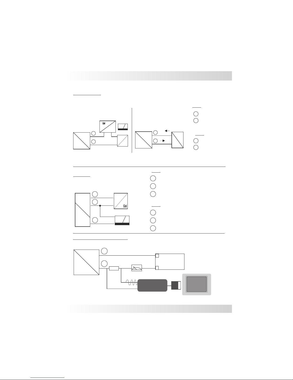
Input
Active
+-
1
4 ... 20 mA
+
_
2
24Vdc
4...20mA (2 wires)
Active
4
2
13
DIN 43650 connector
2 and 3 wires
1
3
-
+ Out
Passive
4...20mA
4...20mA (2 wires)
Passive
1
-
4...20mA
Electrical Connections
1...5Vdc
+
Supply
3
4
Supply
1...5Vdc (3 wires)
2
Out
+
-
1
243
Pressure
Transmitter
+
_
2
07
M12 connector
2 and 3 wires
1
-
+ Out
2
3
1
+
S
_
Pressure
Transmitter
Pressure
Transmitter
08
Electrical Connections
‘
2
3
1
+
S
_
+
-
1...5Vdc
Pressure
transmitter Supply
Vdc
Red (+)
Green (-)
SP10 & SP68
2
1Red (+)
Black (-)
SP10
SP68
HART Modem connection
4...20mA (2 wires)
Passive
+-
1
Supply
+
_
24...20mA
Passive Input
Active
+-
1
4 ... 20 mA
+
_
2
24Vdc
4...20mA (2 wires)
Active
2
1
3
2
1Red (+)
Black (-)
Yellow (Out) 3 wires
SP68
3
2
1Red (+)
Green (-)
Yellow (Out) 3 wires
SP10
4...20mA
Pressure
transmitter
Pressure
transmitter
PC Software
+
2
_
1
Transmitter
®
250?
Padrão Hart modem
PC
+
-
••
USB
Power
Supply
HART
Modem
4...20mA

09
SP96FA & SP98FA
-
Supply
+
+
4...20mA
12 15 18 21 24 27 30 [V]
0
Load max. [Ù]
500
400
300
200
100
SP96FA
0
1200
1000
800
600
400
200
Load max. [Ù]
12 16 20 24 28 32 36[V]
SP98FA
ZS
ZS
Zero & Span adjustment
Supply
Load impedance
4...20mA (2 wires)
Electrical Connections

10
1) Use PTFE tape or o'rings to seal the system.
2) Before installing, make sure the cable connections are
correct and that the line voltage is compatible with the
specifications of the equipment. Use reliable cables and
make sure that they are grounded. Shielded cables
prevent interference and changes in the eletronic signal,
protecting against false measurement output. Avoid
radio frequency interference as it may also cause false
signals and even create a possible malfunction of the
transmitter. When possible, keep hand held
communication equipment away from the SP transmitter.
3) Care should be taken to prevent deformities in the
membrane. You should also be careful not to touch or let
any other object touch the membrane of the sensor
during installation (this does not apply to the units with
ceramic sensing elements) . Any deformity to the surface
of the 316SS silicone filled membrane will damage the
sensor and impair its operation.
Transmitters with cable gland:
Tighten the cable gland as much as possible so that the
cable is securely in place and cannot be pulled through
the cable gland. This will help insure that no moisture is
able to infiltrate into the housing. Don´t forget to attach
the housing cover and tighten all three screws into
position so that there is no infiltration.
4) Protect the transmitter against rain and do not expose it
to excessive heat. Respect the working temperature and
the class protection specified for use.
5) Before installation, for security reasons, make sure the
tank or pipe is empty and without pressure.
6) For transmitters with sealing:
Under no circunstances should you remove the
transmitter seal. Avoid flexing the membrane with your
hands and keep it protected until the installation.
Mounting Notes

11
The transmitters can be installed in various
positions, but the following needs to be taken into
account: For level measurement the installation
should be at the base of the tank or at the point of
minimum level measurement (fig.1). This means
that the reference point for the base measurement
will become the point at which the sensor is
installed which will not necessarily be at the
bottom of the tank.
It is advisable to install a blocking valve between
the transmitter and the connection to perform
maintenance without having to stop the process.
Avoid installing in the tank outlet or near shaker
where there is pressure pulses thus preventing
rapid changes in the signal. For this case it is
necessary the use of still-pipe (Stilling tube) to
absorb the liquid surfaces (Fig. 2).
Min.
Max.
Valve
Height “h”
4...20mA
Base
atm
Pressure
Principle of Operations
The weight of the column of liquid
generates hydrostatic pressure on the
diaphragm of the sensor. When the
density of the product is constant and
the quantity of the liquid is increased
or decreases, there will be a
proportional output from the sensor .
Fig.2
Fig.1
Density
Specific Gravity
Pump
Pressure of the Liquid Column
Water Column
P(mH2O)= relative density.h(m)
System MKS
P(KPa)= density(Kg/m3). g(m/s). h(m)
System MKgfs
P(Kgf/m2)= Specific Gravity(Kg/m3). h(m)
Installation

12
Installation
In situations where the tank is suspended, the
transmitter should always be installed in a point
below the connection using the sealing system
with capillary connection. This type of installation
is required when you want to mount the
transmitter in a better position for viewing (Fig. 3) .
Note: Evaluate what type of product is to be
measured. Aggressive products can damage the
membrane of the sensor element or of the o´ring
seal. That is why it is necessary to determine the
compatability of the product before the unit is
purchased and installed. (Fig. 4).
Install the transmitter so that the electrical cable
dips below the transmitter (or makes a "U") so that
water can drain off the cable without the risk of
infiltrating into the transmitter (Fig 5).
Use a cable with vent tube for all Sitron transmitter
models so that the linearity of the output signal and
the operation of the unit is not compromised (this
special cable can also be provided by Sitron) (Fig.
7).
Avoid installing the transmitter underneath a tank
or were splashing or overflow of the product might
damage the unit. If this is unavoidable, install a
barrier to protect the unit from the product
infiltrating from the outside of the transmitter.
This may also be recommended when the
installation is in an open environment. Weather
variations can create internal condensation, so it
is best to avoid exposing the transmitter to direct
Min.
Max.
height “h”
Sealing
Cappilary
Membrane
Seal
Flange
Fig. 4
Fig. 3
Fig. 5
Fig. 7
Filter
Vent tube
Fig. 6
13
Calibration
Z(zero)
S(span)
Fig.2
Fig.1
SP98FA and SP96FA
Before the calibration of the unit is first tested,
the process should be free of pressure or (if
that is not possible) the unit should first be
tested outside of the vessel.
Make sure the muliti-meter is correctly
connected in series with the source and the
instrument. The scale should be set to mA
First confirm that the current output is at 4mA
(for SPFA units you can adjust the trimpot
"zero".) Turning the trimpot clockwise
increases the current value, and turning it
counterclockwise decreases the value
(Fig.2).
After adjusting (if necessary) the 4mA (zero)
install the unit in the process or fill the vessel
to increase the pressure of the process to the
maximum level desired. If necessary, turn the
trimpot (Span) to adjust the 20mA signal
(Fig. 3).
After calibrating the unit for the first time, it is
recommended that the you re-check the zero
and span ouput with your multimeter. This will
confirm that the unit is properly calibrated or if
further adjustment is necessary.

14
Seal the thread with Teflon tape before
installation.
(Fig. 1).
When tightening the sensor, use only use the
316S.S. hexagon fitting to achieve a seal, do not
twist with the body of the sensor.
The transmitter should not be dropped or suffer
any impact or fall, as this can damage the
electronics or the sensor (Fig.3).
Electrical connection with DIN connector:
Figure 4. Shows the steps for proper assembly of
the connector. When you tighten the threaded
part, stop once you feel that the rubber seal is at its
maximum compression point. Do not over-tighten
the thread. It is very important that the connector is
securely sealed so that the class protection is
maintained and no infiltration occurs.
Do not turn or handle by the housing
(Fig. 2).
Do not insert any object into the entry point of the
transmitter supply. This will immediately damage
the membrane.
Fig. 1
Fig. 2
Fig. 3
Handling
Rubber seal connection
Screw
Screw O’ring
Cable seal
Cable gland
Enclosure
Fig.4
Cable
Cable
Vent tube
Vent tube

15
Ceramic capacitive
Cable gland ½”NPT
4...20mA (2 wires )
-1 to 40 Bar
IP 65
22mA max.
316 SS
-10 to +80ºC
12...30Vdc
3 x F.S.
+/- 0.5%
SP98FA
ZS
Fiberglass Nylon
Zero & Span
N1
BSP or NPT - flange or sanitary
Technical Specifications
Housing
Adjustment
Application
Power supply
Consumption
Output
Accuracy
Sensor type
Range
Electrical connection
Process connection
Body material
Work temperature
Over pressure
Class protection
Pressure and Level measurement for liquids and gas

16
Technical Specifications
316 SS piezoresisitve silicon
4...20mA (2 wires )
-1 to 200 Bar
IP 65
22mA max.
316 SS
-10 to +80ºC
12...30Vdc
3 x F.S.
+/- 0.5%
SP96FA
ZS
Housing Fiberglass Nylon
Adjustment Zero & Span
N1
Cable gland ½”NPT
BSP or NPT - flange or sanitary
Application
Power supply
Consumption
Output
Accuracy
Sensor type
Range
Electrical connection
Process connection
Body material
Work temperature
Over pressure
Class protection
Pressure and Level measurement for liquids and gas

17
316 SS silicon piezoresistive
Polyethylene
4...20mA (2 wires )/ ,1...5V, 0...5V (3 wires)
0.1 to 1000 Bar
IP 68
22mA max.
304 SS
-10° to + 80°C
12...30Vdc
3 x F.S.
+/- 0.5%
SP68
M20*1.5” / 1/2”(BSP or NPT) (others)
Reverse polarity
3
2
1Red (+)
Black (-)
Yellow (Out) 3 wires
Technical Specifications
Application
Power supply
Consumption
Protection
Output
Accuracy
Sensor type
Range
Electrical connection
Process connection
Body material
Work temperature
Over pressure
Class protection
Pressure and Level measurement for liquids and gas

18
316 SS piezoresistive
Silicon or olive oil
DIN43650 or M12 connector
4...20mA (2 wires ) 0...4,5V (3 wires) upon request
0,1 to 1000 Bar
IP 65
22mA max.
304 SS
12...30Vdc
3 x F.S.
+/- 0,5%
SP30
M20*1.5 , 1/2” BSP or 2”TC
0 to +80ºC ( olive oil sensor)
-10° a + 80°C ( silicon sensor)
(-) Negativo
(+) Positivo
Out (V)
2
3
1
DIN 43650 Connector
1
3
4
2
( ) GND
4
Reversal polarity
Technical Specifications
Application
Power supply
Electrical connection
Process connection
Work temperature
Body material
Consumption
Sensor type
Protection
Accuracy
Range
Output
Class protection
Over pressure
Pressure and Level measurement for liquids and gas

19
316 SS silicon piezoresistive
Cable or M12 connector
4...20mA (2 wires ) 0...5 e 1...5V (3 wires)
0,2 to 250 Bar
IP 65
22mA max.
304 SS
-10 to +80ºC
12...30Vdc
3 x F.S.
+/- 0.5%
SP10
G1/4” / 1/4"-18 NPT / 1/8"-27 NPT / M14*1.5 /
M12*1.5 / 1/4"-19 PT / 7/16"-20 UNF (female)
3
2
1Red (+)
Green (-)
Yellow (Out) 3 wires
Reversal polarity
Technical Specifications
Application
Power supply
Electrical connection
Process connection
Work temperature
Body material
Consumption
Sensor type
Protection
Accuracy
Range
Output
Class protection
Over pressure
Pressure and Level measurement for liquids and gas

Accuracy
Range
Sensor type
Power supply
Application
Consumption
Output
Protection
4...20mA (2 wires ) 0,5...4,5/ 1...5V/ 0...5V (3 wires) upon request
Process connection
Electrical connection
BSP ou NPT - flange or sanitary
Work temperature
Class protection
Body material
Over pressure
SP21
316 SS silicon piezoresistive
DIN43650 or M12 connector
0.1 to 1000 Bar
22mA max.
12...30Vdc
2
Reverse polarity
+/- 0.25%
1
3
M12 connector
304 SS
-10° to + 80°C
DIN 43650 connector
2
Technical Specifications
IP 65 / IP66 / IP67
3 x F.S.
3
43
4
2
1
3
4
4
2
1
1
Out (V)
(-) Negative
(+) Positive
Out (V)
( ) GND
( ) GND
20
(-) Negative
(+) Positive
30mm
Ø
47mm
30mm
Ø
28mm
56mm
28mm
56mm
47mm
SP21 SP21- IP66
30mm
Ø
65mm 35mm
36mm
SP21- IP67
Hex. 1.1/16”
Pressure and Level measurement for liquids and gas
This manual suits for next models
8
Table of contents
Popular Transducer manuals by other brands


HBM
HBM U1A Mounting instructions

Daiichi Electronics
Daiichi Electronics FAETT2-92A-33 instruction manual

S+S Regeltechnik
S+S Regeltechnik PREMASGARD 111 Series Operating Instructions, Mounting & Installation

Humminbird
Humminbird TROLLING MOTOR TRANSDUCER installation guide

WIKA
WIKA F2802 operating instructions

JUMO
JUMO HC103 operating instructions