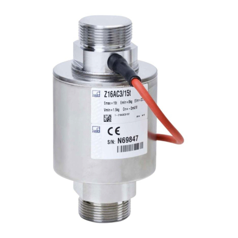
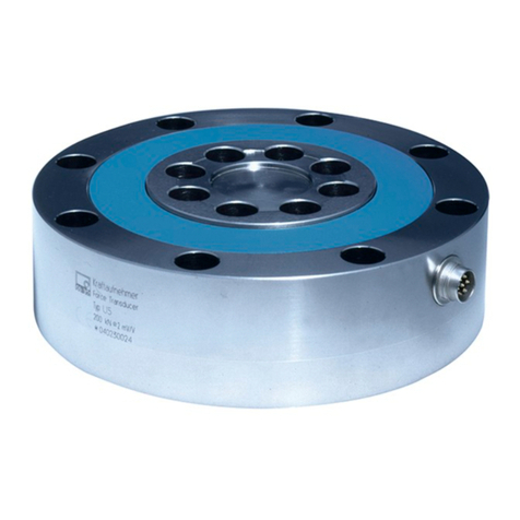
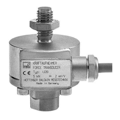
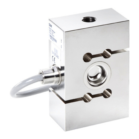
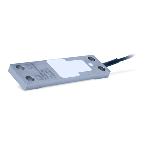
HBM U15 Series User manual

A2100-4.0 en/de
Force transducer
Kraftaufnehmer
Mounting Instructions
U15
Montageanleitung

English Seite 3 - 29. . . . . . . . . . . . . . . . . . . . . . . . . . . . . . . . . . . . . . . . . . . . . . . . .
Deutsch Page 31 - 57. . . . . . . . . . . . . . . . . . . . . . . . . . . . . . . . . . . . . . . . . . . . . . .

3
U15
A2100-4.0 en/de HBM
Contents Page
English
Safety instructions 4. . . . . . . . . . . . . . . . . . . . . . . . . . . . . . . . . . . . . . . . . . . . . .
1 Scope of supply 7. . . . . . . . . . . . . . . . . . . . . . . . . . . . . . . . . . . . . . . . . . . . .
2 Application notes 8. . . . . . . . . . . . . . . . . . . . . . . . . . . . . . . . . . . . . . . . . . . .
3 Conditions on site 10. . . . . . . . . . . . . . . . . . . . . . . . . . . . . . . . . . . . . . . . . . .
3.1 Ambient temperature 10. . . . . . . . . . . . . . . . . . . . . . . . . . . . . . . . . . . . .
3.2 Moisture 10. . . . . . . . . . . . . . . . . . . . . . . . . . . . . . . . . . . . . . . . . . . . . . . .
3.3 Degree of protection 10. . . . . . . . . . . . . . . . . . . . . . . . . . . . . . . . . . . . .
4 Mechanical installation 11. . . . . . . . . . . . . . . . . . . . . . . . . . . . . . . . . . . . . . .
4.1 Important precautions during installation 11. . . . . . . . . . . . . . . . . . . .
4.2 General installation guidelines 11. . . . . . . . . . . . . . . . . . . . . . . . . . . . .
4.3 Mounting accessories for compressive loading 12. . . . . . . . . . . . . . .
4.4 Mounting accessories for tensile loading 13. . . . . . . . . . . . . . . . . . . .
5 Electrical connection 15. . . . . . . . . . . . . . . . . . . . . . . . . . . . . . . . . . . . . . . . .
5.1 Notes on cabling 15. . . . . . . . . . . . . . . . . . . . . . . . . . . . . . . . . . . . . . . . .
5.2 Pin assignment 16. . . . . . . . . . . . . . . . . . . . . . . . . . . . . . . . . . . . . . . . . .
5.3 TEDS transducer identification 17. . . . . . . . . . . . . . . . . . . . . . . . . . . . .
6 Versions and order numbers 20. . . . . . . . . . . . . . . . . . . . . . . . . . . . . . . . . .
7 Specifications 21. . . . . . . . . . . . . . . . . . . . . . . . . . . . . . . . . . . . . . . . . . . . . . .
8 Dimensions 23. . . . . . . . . . . . . . . . . . . . . . . . . . . . . . . . . . . . . . . . . . . . . . . . .
8.1 Mounting dimensions of the connection variants 24. . . . . . . . . . . . .
8.2 Accessories 25. . . . . . . . . . . . . . . . . . . . . . . . . . . . . . . . . . . . . . . . . . . . .

U15
4
A2100-4.0 en/deHBM
Safety instructions
Intended use
The U15 force transducer is to be used exclusively for force measurement
tasks and directly related control tasks. Use for any additional purpose shall
be deemed to be not as intended.
In the interests of safety, the transducer should only be operated as described
in the Mounting Instructions. It is also essential to comply with the legal and
safety requirements for the application concerned during use. The same
applies to the use of accessories.
The transducer is not a safety element within the meaning of its use as in
tended. For safe and trouble‐free operation, this transducer must not only be
correctly transported, stored, sited and installed but must also be carefully op
erated and maintained.
General dangers of failing to follow the safety instructions
U15 force transducers are state‐of‐the‐art and failsafe.
Transducers can give rise to remaining dangers if they are inappropriately
installed and operated by untrained personnel.
Everyone involved with the installation, commissioning, maintenance or repair
of a force transducer must have read and understood the Mounting Instruc
tions and in particular the technical safety instructions.
Remaining dangers
The scope of supply and performance of the transducer covers only a small
area of force measurement technology. In addition, equipment planners, in
stallers and operators should plan, implement and respond to the safety engi
neering considerations of force measurement technology in such a way as to
minimize remaining dangers. Prevailing regulations must be complied with at
all times. There must be reference to the remaining dangers associated with
force measurement technology.

5
U15
A2100-4.0 en/de HBM
Remaining dangers are indicated in these Mounting Instructions by the
following symbols:
Symbol: WARNING
Meaning: Dangerous situation
Warns of a potentially dangerous situation in which failure to comply with
safety requirements can result in death or serious physical injury.
Symbol: CAUTION
Meaning: Possible dangerous situation
Warns of a potentially dangerous situation in which failure to comply with
safety requirements could result in damage to property or some form of
physical injury.
Symbol: NOTE
Means that important information about the product or its handling is being
given.
Symbol:
Meaning:CE mark
The CE mark enables the manufacturer to guarantee that the product
complies with the requirements of the relevant EC directives (the Declaration
of Conformity can be found at http://www.hbm.com/HBMdoc).
Conversions and Modifications
The transducer must not be modified from the design or safety engineering
point of view except with our express agreement. Any modification shall ex
clude all liability on our part for any damage resulting therefrom. This excludes
fitting and removing the adapter, as described in Chapter 4.

U15
6
A2100-4.0 en/deHBM
Qualified personnel
This device must only be installed by qualified personnel, strictly in
accordance with the specifications and in conjunction with the safety
requirements and regulations listed below. It is also essential to observe the
appropriate legal and safety regulations for the application concerned. The
same applies to the use of accessories.
Qualified personnel means persons entrusted with the installation, assembly,
commissioning and operation of the product, who possess the appropriate
qualifications for their function.
Conditions at the place of installation
Protect the transducer from moisture and dampness or weather conditions
such as rain, snow, ice and salt water.
Avoid contact with corrosive media.
Maintenance
The U15 force transducer is maintenance‐free.
Accident prevention
The prevailing accident prevention regulations must be taken into account,
even though the breaking force is well in excess of the nominal (rated) force.

7
U15
A2100-4.0 en/de HBM
1 Scope of supply
•U15 force transducer (version‐dependent)
•U15 operating manual
Accessories (not included in scope of supply):
•Cables/plugs
Order number
1-KAB157-3 Connection cable with bayonet locking; IP67; 3 m long, Ø6.5 mm; TPE outer
sheath; 6 x 0.25 mm2; free ends, shielded
1-KAB158-3 Connection cable with screw locking; IP54; 3 m long, Ø6.5 mm; TPE outer
sheath; 6 x 0.25 mm2; free ends, shielded
3-3312.0382 Loose connecting socket, bayonet locking
3-3312.0354 Loose connecting socket, screw locking
1-EEK4 Ground cable (400 mm long)
1-EEK6 Ground cable (600 mm long)
1-EEK8 Ground cable (800 mm long)

U15
8
A2100-4.0 en/deHBM
2 Application notes
Two mechanical versions are available for force transducers of the U15 type
series:
Single bridge Double bridge
The transducers are suitable for measuring tensile and compressive forces.
Because they provide highly accurate static force measurements, they must
be handled very carefully. Particular care must be taken when transporting
and installing the devices. Dropping or knocking the transducers may cause
permanent damage.
The specifications list the permissible limits for mechanical, thermal and
electrical stress. It is essential that these are taken into account when
planning the measuring set‐up, during installation and ultimately, during
operation.
Plug protection (Option)
An additional square profile around the plug protects it from mechanical da
mage.

9
U15
A2100-4.0 en/de HBM
CAUTION
The flange screws and the tensile adapter are permanently moun
ted onto the transducer and must not be loosened; otherwise the
specifications may deviate from the guaranteed values and the ca
libration.

U15
10
A2100-4.0 en/deHBM
3 Conditions on site
The transducer is not suitable for use in nuclear power stations or for
continuous exposure to seawater.
3.1 Ambient temperature
The temperature effects on the zero signal and on the sensitivity are
compensated. To obtain optimum measurement results, the nominal (rated)
temperature range must be observed. Temperature‐related measurement
errors are caused by heating on one side (e.g. radiant heat) or by cooling. A
radiation shield and all‐round thermal insulation produce noticeable
improvements, but must not be allowed to form a force shunt.
3.2 Moisture
Avoid prolonged exposure to extreme moisture or a tropical climate.
Otherwise the probability of slight corrosion of the screws and variations of the
zero point increases.
NOTE:
Moisture must not be allowed to penetrate the free end of the
connection cable.
3.3 Degree of protection
The IP degree of protection defins the protection provided by an enclosure
against ingress of solid foreign objects or water. U15 provides IP67 protection
per DIN 60529.

11
U15
A2100-4.0 en/de HBM
4 Mechanical installation
4.1 Important precautions during installation
•Handle the transducer gently.
•When measuring compressive forces, make sure the support structure is
rigid.
•The force application surfaces must be perfectly clean and fully bearing.
•Observe the depths of engagement for threaded rods or knuckle eyes.
•Do not overload the transducer.
•Welding currents must not be allowed to flow over the transducer. If there is
a risk that this might happen, you must use a suitable low‐ohm connection
to electrically bypass the transducer. HBM, forexample, provides the highly
flexible EEK ground cable, which can be screwed on, both above and
below the transducer.
WARNING
Additional safeguards must be provided if there is a risk that
overloading the transducer may cause it to break, which could put
people at risk.
4.2 General installation guidelines
The forces to be measured must act on the transducer as accurately as
possible in the direction of measurement.
CAUTION
Torsional and bending moments, eccentric loading and lateral
forces may produce measurement errors and destroy the
transducer, if limit values are exceeded.
The maximum parasitic forces ‐ lateral forces, bending and torsional
moments ‐ must be observed during installation and operation of the
transducer (also see Chapter 7, Specifications).
Strain gage application in the measuring body is terminated by covers at top
and bottom. These covers must not be loaded or damaged.

U15
12
A2100-4.0 en/deHBM
4.3 Mounting accessories for compressive loading
Thrust pieces according to ISO 376 are available for introducing comprerssive
forces. They can be mounted directly onto the threaded spherical pin.
F
Thrust piece
Transducer
Type Thrust piece
Order no.
U15/2,5kN-50kN 1-EDO4/20kN
U15/100kN-250kN 1-U15/250kN/EDO
U15/500kN 1-U15/500kN/EDO
U15/1MN 1-EDO4/500kN

13
U15
A2100-4.0 en/de HBM
4.4 Mounting accessories for tensile loading
Knuckle eyes and tensile force application parts (ZKM) to ISO 376 are avail
able for installing the U15. These mounting aids prevent the introduction into
the transducer of torsional moment and, where 2 knuckle eyes are used,
bending moment, as well as lateral and oblique loads.
These mounting accessories are only intended for static tensile loading of the
transducer.
Installing knuckle eyes
•Screw the knuckle eye thread into the transducer thread until the stop is
reached and then screw it one and a half turns back out.
f
a
∅B
W
Type Knuckle eye top / bottom
Order no. a f W B
U15/2,5kN-50kN 1-Z4/20kN/ZGOW /
1-Z4/20kN/ZGUW app. 209 app. 246 21 16
U15/100kN-250kN 1-ZGIM33F / 1-ZGAM33F app. 362 app. 488 35 50
U15/500kN 1-ZGIM42F / 1-ZGAM42F app. 418 app. 554 44 60
U15/1MN 1-ZGIM72F / 1-ZGAM72F app. 588 app. 792 60 90

U15
14
A2100-4.0 en/deHBM
Installing tensile force application parts:
•Screw the ZKM force application part thread into the transducer thread until
the stop is reached and then screw it one and a half turns back out.
ZKM tensile force application part to ISO 376
B
ØD
C
Type ZKM
Order no. BCD
min max
U15/2,5kN-50kN 1-Z4/20kN/ZKM app. 372 appr. 277 appr. 313 35
U15/100kN-250kN 1-U15/250kN/ZKM app. 478 appr. 364 appr. 404 64
U15/500kN 1-U15/500kN/ZKM app. 650 appr. 447 appr. 539 90
U15/1MN 1-U15/1MN/ZKM app. 833 appr. 549 appr. 679 120

15
U15
A2100-4.0 en/de HBM
5 Electrical connection
5.1 Notes on cabling
•Use shielded, low‐capacitance HBM cables only.
•Do not route measurement cables parallel to power lines or control circuits.
If this is not possible (in cable pits, for example), protect the measurement
cable with a rigid steel conduit, for example and keep it at least 50 cms
away from the other cables. The power lines or control circuits should be
twisted (15 twists per meter).
•Avoid stray fields from transformers, motors and contact switches.
•Do not ground the transducer, amplifier and indicator more than once. All
the devices in the measurement chain must be connected to the same
grounded conductor.
•The connection cable shielding is connected to the plug housing.
Connecting to terminals:
•The shield can be accessed via a cut in the cable sheath
•Connect the shield extensively to the housing ground.
Connecting to a plug:
Connect the cable shield extensively to the connector housing.
To extend the cabling, we recommend shielded pairs of HBM low‐capacitance
measurement cables.

U15
16
A2100-4.0 en/deHBM
5.2 Pin assignment
Transducers are available with the following electrical connections:
•Bayonet connection: plug‐compatible with the MIL-C-26482 series 1
connection
or
•Screw‐locking: plug‐compatible with the MIL-C-26482 series 1 connection
(Ordering information, see page 7)
If the transducer is connected in accordance with the following connection
diagram, the output voltage at the amplifier is positive when the transducer is
under tensile loading.
wh (white)
bk (black)
rd (red)
bu (blue)
gn (green)
gy (gray)
Measurement signal (+) UA
Excitation voltage (+) UB
Sense lead (-) (TEDS*)
Sense lead (+)
Excitation voltage (-) UB(TEDS*)
Measurement signal (-) UA
Cable shield, connected to the housing
AF
B
C
E
D
B
D
C
A
F
E
Device plug pin assignment Free end cable assignment
* Option
Fig. 5.1: Pin assignment for plug, KAB 157-3 and KAB 158-3
The cable shield is connected in accordance with the Greenline concept (see
http://www.hbm.com/Greenline). This encloses the measurement system in a
Faraday cage, so that it is not affected by electromagnetic interference.
When connecting plugs to cables with free ends, the shielding must be
connected extensively. With other connection techniques, a good EMC shield
must be provided in the stranded area, where the shielding is also extensively
connected.

17
U15
A2100-4.0 en/de HBM
5.3 TEDS transducer identification
TEDS stands for ”Transducer Electronic Data Sheet”. An electronic data sheet
is stored in the transducer as defined in the IEEE 1451.4 standard, making it
possible for the measuring amplifier to be set up automatically. A suitably
equipped amplifier imports the transducer characteristics (electronic data
sheet), translates them into its own settings and measurement can then start.
At connection 7 (to ground at PIN 2), there is a digital identification system
available. The basis for this is a 1‐wire EEPROM DS2433, made by
Maxim/Dallas.
HBM provides you with the TEDS Editor for storing your data. This is a
component part of the MGCplus Setup Assistant software (see the TEDS
operating manual ”TEDS data memory in the transducer” on the Internet at
www.hbm.com/TEDS).
The Editor also makes it possible to manage the different user rights to
protect the fundamental transducer data from being inadvertently overwritten.
Content of the TEDS memory as defined in IEEE 1451.4:
The information in the TEDS memory is organized into templates which are
prestructured to store defined groups of data in table form. Only the entered
values are stored in the TEDS memory itself.
The amplifier firmware assigns the interpretation of the respective numerical
values. This places a very low demand on the TEDS memory.
The memory contents are divided into four areas:
Area 1:
An internationally unique identification number (cannot be changed).
Area 2:
The base area (basic TEDS), to the configuration defined in standard
IEEE1451.4. The transducer type, the manufacturer and the transducer serial
number are contained here.
Area 3:
Data specified by the manufacturer are contained in this area:
These specify
- the transducer type,
- the measured quantity,
- the electrical output signal,
- the required excitation.

U15
18
A2100-4.0 en/deHBM
HBM has already written the Bridge Sensor template for the U15 force
transducer.
The user can also write other templates, such as the Signal Conditioning
template.
Area 4:
The actual user can modify the last of these areas with, for instance:
- a short comment in text form,
- filter settings,
- zero value.
Example:
Content written by HBM, on the basis of the individual test certificate: Area 3
of the U15/5kN sensor with identification no. 123456, made by HBM on
1.6.2006.
Template: Bridge Sensor
Parameters Value 1) Unit Change
re
quires
rights
to level:
Explanation
Transducer Electrical
Signal Type Bridge
Sensor ID
Minimum Force/Weight 0.000 N CAL The physical measured quantity and
unit are defined when the template
is created, after which they cannot
be changed.
Maximum Force/Weight 5.000k N CAL
Minimum Electrical
Value 0.00000m V/V CAL The difference between these
values is the sensitivity according to
the HBM test certificate (tensile
force) or from calibration1).
Maximum Electrical
Value +2.00078m V/V CAL
Mapping Method Linear This entry cannot be changed.
Bridge type Full ID The bridge type. The following
values are available for selection:
”Quarter” for a quarter bridge, ”Half”
for a half bridge, ”Full” for a full
bridge. Some HBM transducers can
be connected as half bridges or full
bridges according to choice. For
HBM's SG‐based transducers, the
bridge type is always full bridge.
Impedance of each
bridge element 345.0 Ohm ID Input resistance according to the
HBM data sheet.
Response Time 1.0000000u sec ID Of no significance for HBM
transducers.
Excitation Level
(nominal) 5.0 V ID Nominal (rated) excitation voltage
according to the HBM data sheet

19
U15
A2100-4.0 en/de HBM
Parameters Value 1) Unit Change
re
quires
rights
to level:
Explanation
Excitation Level
(minimum) 0.5 V ID Lower limit for the operating range
of the excitation voltage according
to the HBM data sheet.
Excitation Level
(maximum) 12.0 V ID Upper limit for the operating range
of the excitation voltage according
to the HBM data sheet.
Calibration Date 1-Jun-2006 CAL Date of the last calibration or
creation of the test certificate (if no
calibration carried out), or of the
storage of the TEDS data (if only
nominal (rated) values from the data
sheet were used). Format:
day-month-year.
Abbreviations for the months: Jan,
Feb, Mar, Apr, May, Jun, Jul, Aug,
Sep, Oct, Nov, Dec.
Calibration Initials HBM CAL Initials of the calibrator or calibration
laboratory concerned.
Calibration Period
(days) 730 days CAL Time before recalibration, calculated
from the date specified under
Calibration Date.
Measurement location
ID 0USR Identification number for the
measuring point. Can be assigned
according to the application.
Possible values: a number from 0 to
2047. If that is not enough, the HBM
Channel Comment template can
also be used for this purpose.
1) Typical values for an HBM U15/5kN type force transducer
When creating the Bridge Sensor template, the manufacturer defines the
physical measured quantity and the physical unit.
The available unit for the particular measured quantity is specified in the IEEE
Standard. For the measured quantity of force, this is the unit N.
At the time of creating the template it is also necessary to choose between the
options ”Full Precision”, ”mV/V” and ”uV/V” for the accuracy of the
characteristic transducer curve mapped in TEDS.
HBM always opts for ”Full Precision” here, in order to be able to use full digital
resolution. This choice is also recommended to users who program the TEDS
memory themselves.
For more extensive information about TEDS, look in the TEDS Operating
Manuals on the Internet at www.hbm.com/TEDS

U15
20
A2100-4.0 en/deHBM
6 Versions and order numbers
Code Measuring
range
2k50 2.5 kN
5k00 5 kN
10k0 10 kN
25k0 25 kN
50k0 50 kN
100k 100 kN
250k 250 kN
500k 500 kN
1M00 1 MN
Number
of mea-
suring
bridges
Transducer
identification Plug
protection
Plug version
Bridge A
Plug version
Bridge B
Single
bridge
SB
without
TEDS
S
without plug
protection
U
Bayonet connector
B
Bayonet connector
B
Double
bridge
DB
with TEDS
T
with plug
protection
P
Threaded
connector
G
Threaded
connector
G
K‐U15‐ 25k0 DB T P B G
Number of
measuring
bridges
When being used as a reference transducer, the second measuring bridge can be used
as the input signal for the machine control.
Transducer
identification
TEDS integration (integrated electronic data sheet) in accordance with IEEE1451.4
Plug
protection
Mechanical protection through the installation of an additional square profile around the
connector.
Dimensions approx.: width x height x depth: 30x30x20
Plug version
bridge A
Device plug with bayonet locking (PT02E10-6P‐compatible) or screw‐fitted device plug
(PC02E10-6P‐compatible).
Plug version
bridge B
Bayonet locking (PT02E10-6P‐compatible) or screw‐fitted device plug
(PC02E10-6P‐compatible). Both these connection variants are often used for
differentiation in the double‐bridge version.
Table of contents
Languages:
Other HBM Transducer manuals