SIUS AC13 Installation manual

Electronic scoring systems
• Installation
• Start-up
• Maintenance
AC13
SIUS AG
Im Langhag 1 | CH-8307 Effretikon | Switzerland
Phone +41 52 354 60 60
www.sius.com | [email protected]
2
Electronic scoring systems
B-INWA- AC13-en – 04/19
AC13
Open system for
supersonic
ammunition
Table of contents Page
General
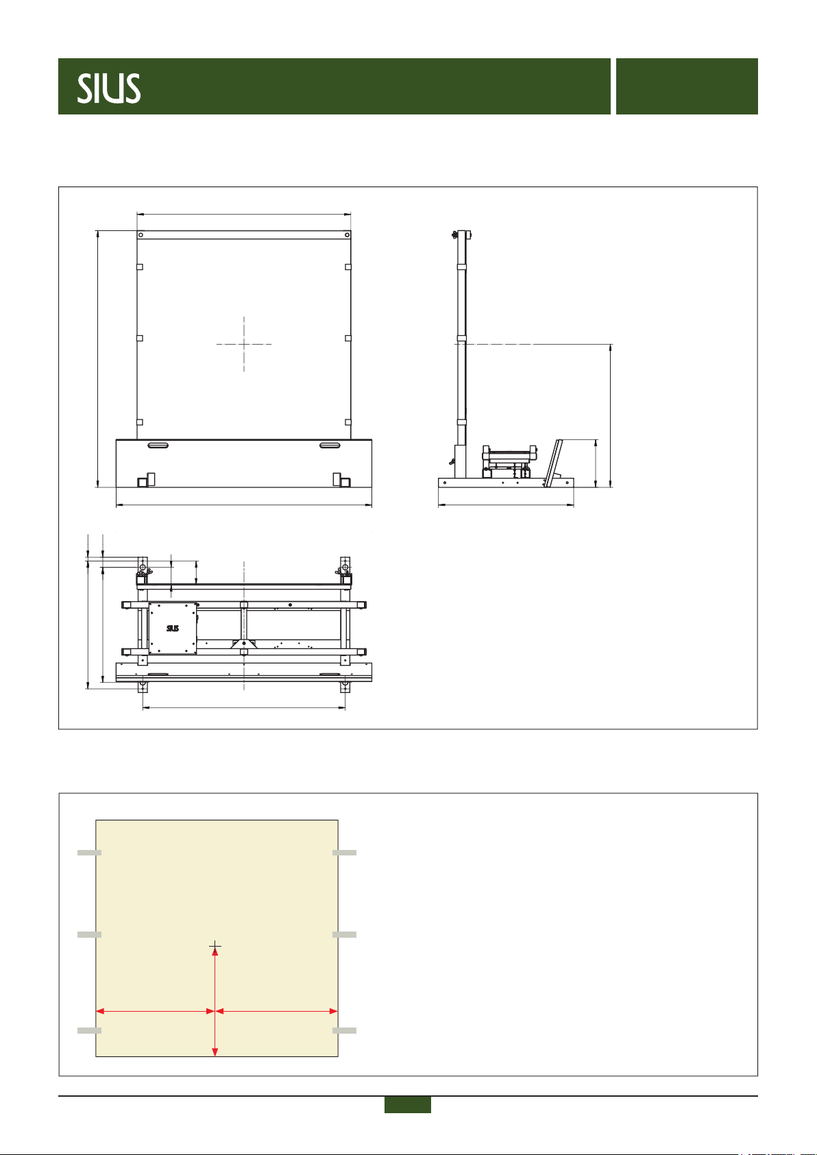
Dimensions of the system / Centre of measurement 3
Installation – System with connection via cable
Overview and cabling 4
Installation target line / Cabling and connection of control unit 5
Installation – System with connection via radio
Overview and cabling 6
Installation target line / Installation ring line 7–8
Installation – Target and protection plaes
Mounting of wooden target frame 9
Target front masks with hunting pictures / Circular target pictures 10
Mounting of multi wall panel with target front mask 11
Mounting of protection plates 12
Accessories
Feet, wheel casters, oor mounts 13–14
Start-up
Positioning 15
Start-up 16–17
Maintenance and function control
Maintenance and function control 18–19
3
Electronic scoring systems
B-INWA- AC13-en – 04/19
AC13
Open system for
supersonic
ammunition
General
585mm 585mm
552,5mm
x = 0mm
y = 0mm
Center of measurement on basic multi wall panel S110AA022
1
1
2
2
3
3
4
4
5
5
6
6
A A
B B
C C
D D
REV Änderungen Datum Name
Datum Name
Gez.
Gepr.
Norm.
Maßstab Blatt
SPU12 Massblatt
.
24.05.2016 weberl
1
A3
.
.
C:\Users\Public\Products\TARGETS\Accessoires\SPU12\Mechanik\SPU12\SPU12 Massblatt.idw
.
.
Im Langhag 1 CH - 8307 Effretikon
Tel: +41 52 354 60 60 Fax: +41 52 354 60 66
SIUS
1405
7401400
1170
700
630
1108
262
783.4
131
96
55
20
1
1
2
2
3
3
4
4
5
5
6
6
A A
B B
C C
D D
REV Änderungen Datum Name
Datum Name
Gez.
Gepr.
Norm.
Maßstab Blatt
SPU12 Massblatt
.
24.05.2016 weberl
1
A3
.
.
C:\Users\Public\Products\TARGETS\Accessoires\SPU12\Mechanik\SPU12\SPU12 Massblatt.idw
.
.
Im Langhag 1 CH - 8307 Effretikon
Tel: +41 52 354 60 60 Fax: +41 52 354 60 66
SIUS
1405
7401400
1170
700
630
1108
262
783.4
131
96
55
20
Dimensions of the system

4
Electronic scoring systems
B-INWA- AC13-en – 04/19
AC13
Open system for
supersonic
ammunition
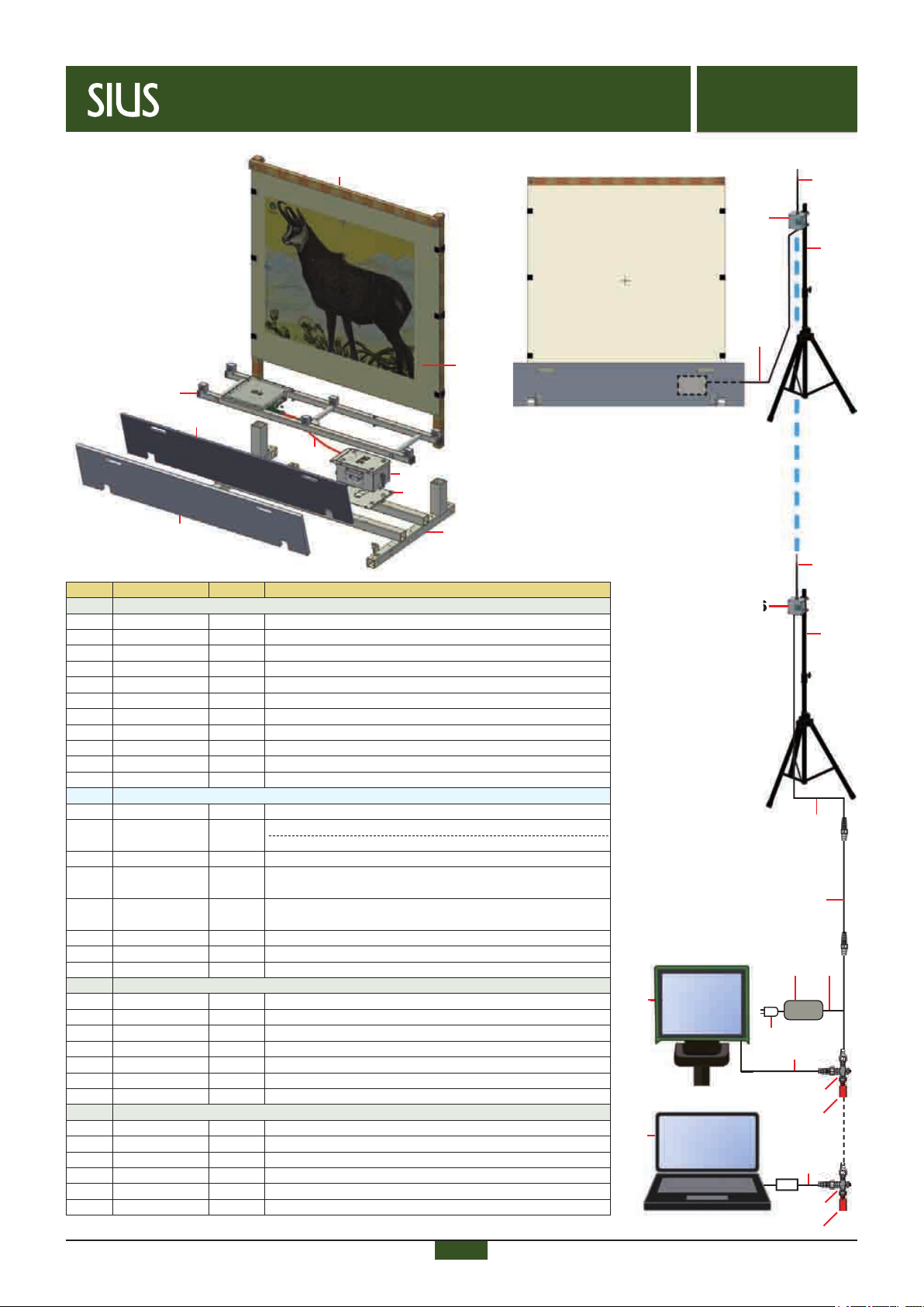
InstallationSystem with connection via cable
System with connection via cable
PC/Laptop
SIUSLANE
B2
B3
B5
A
C2
B4
B1
A1
A2
A3
A4
A5
A6
A7
A8
B6
B1
B7
B8
1
B6
Pos. Article no. Pcs. Description
A Target line
A1 AC13V2 1 Acoustic Eye AC13 with integrated target electronic
A2 SPU12 1 Support with target holder for AC13
A3 LNRBOX-V2 1
Lane number box with AC surge protection,stufng box 8–11mm
A4 KS027-0.85 1
Cable Cannon 10p fem-male 0.85m with increased power supply
A5 SPU12AN001 1 Protection plate: sheet steel DIN1.8720,
1400x266x12mm
A6 SPU12AN004 1
Debris protection, PE 300 nature, 1400x266x20mm
A7 SPU12AN003 1 Wooden frame (holder of basic multi wall panel with front mask)
A8 S110AA022 1 Basic multi wall panel for front mask
B Cables and supply
B1 KL001-2.0 1 Cable LTW male–fem 2.0m
B2 KL013 1 Y power cable for NT211
B3 NT211 1 Power supply for 10 lines 225W with LTW 230V
B4 VK-LTW2V2 1 Distribution box without lightning protection
B5 KV020-L* 1 Cable power supply & LON, 4-wire (up to 400m)
(*indicate the required length)
B6 KL001-T 1 T-Adapter fem/fem/male LTW IP67
B7 KL001-R 1 Terminating resistor, red, male LTW IP67
B8 VJ45R-V1 1 Terminating resistor for clamp 100Ω
C Firing line
C1 M95V0 1 Control unit 10"
C2 1 Windows-PC/Laptop with current hardware (on request)
SNI210-LANE 1 USB-LON-Dongle (yellow)
SIL 1
SIUSLANE data acquisition and display software
Reference Country-specic power supply cable > AA1**
Diagram: single lane, distance up to 400m
(larger distances on request)
oder
C1 M95

-
5
Electronic scoring systems
B-INWA- AC13-en – 04/19
AC13
Open system for
supersonic
ammunition
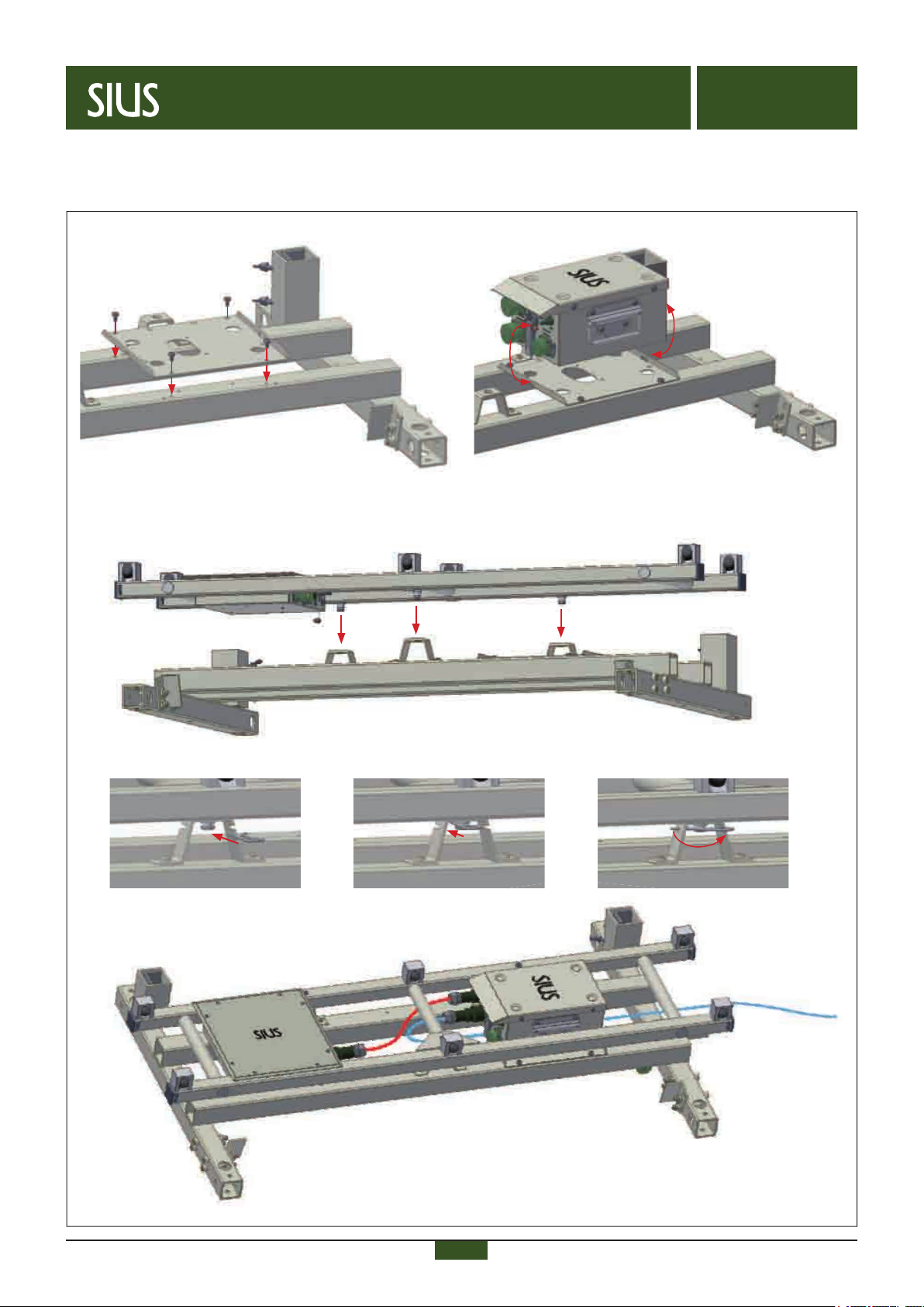
Installation target line
Cabling and connection of control unit
Connection of cables
Cables:
red = electronic of detection system AC13 <> LNR-box
blue = LNR-box <> control unit
➜ to control unit
System with connection via cable
Cabling and connection of control unit are accomplished according to the scheme on page 4.
The equipment must be connected to electricity before starting-up.
Mounting of LNR-box
3.1 Plug the detection system AC13 on the holder.
Assembly of detection system AC13
3.2 Insert the safety pin. 3.3 Snap in the safety pin. 3.4 Turn and lock the safety pin.
Screw the LNR-box on the support/target holder (right side).
Installation
Connection of cable KV020
inside LNR-box:
1. not used (PE)
2. white (Net A)
3. brown (Net B)
1. green (GND)
2. yellow (24V)
3. grey (PE=shield)
KV020
Terminating resistor:
1. not used (PE)
2. not used (24V)
3. not used (GND)
1. (Net A)
2. (Net B)
3. not used (PE)
Terminating resistor
6
Electronic scoring systems
B-INWA- AC13-en – 04/19
AC13
Open system for
supersonic
ammunition
System with connection via radio Installation
PC/Laptop
SIUSLANE
oder
B2
B3
C1
C2
B1
R9
A
R6
R6
R8
R7
Pos. Article no. Pcs. Description
A Target line
A1 AC13V2 1 Acoustic Eye AC13 with integrated target electronic
A2 SPU12 1 Support with target holder for AC13
A3 SPU12AN002 1 Ground plate for battery
A4 BPC202-SLA7 1 Battery Packet LOMAH 24V 7Ah
NT202-160 1 Power supply110–240V
AS695 1 Adapter 3-pole
A5 KS027-0.85 1
Cable Cannon 10p fem-male 0.85m with increased power supply
A6 SPU12AN001 1 Protection plate: sheet steel DIN1.8720,
1400x266x12mm
A7 SPU12AN004 1
Debris protection, PE 300 nature, 1400x266x20mm
A8 SPU12AN003 1
Wooden frame (holder of basic multi wall panel with front mask)
A9 S110AA022 1 Basic multi wall panel for front mask
R Radio
R6 RBLONV2 1 Radio Box 2.4GHz LT2510
R7 AA0511
RBLONA503
1
1
Omni directional antenna 9dB (up to 400m distance)
Extension antenna 40cm, type N, male-female (option)
AAG192 1 Planar antenna 14dB (over 400m distance, up to 1200m)
R8 RBLONAN002 1 3-leg stand (option), height 130–200cm, incl. pipe clamp
for RBLON (large distance > target and ring line)
RBLONAN001 1 Aluminum tube (option), height 100cm, incl. pipe clamp
for RBLON (large distance > target and ring line)
RBLONAN003 1 Pipe clamp for RBLON (option), clamping range Ø 24–26mm
R9 KS027-8 1
Cable Cannon 10p fem-male 8.0m with increased power supply
R10 KM020-1.0 1 Cable Cannon 10p fem-LTW male 1.0m
B Cables and supply
B1 KL001-2.0 1 Cable LTW male–fem 2.0m
B2 KL013 1 Y power cable for NT211
B3 NT211 1 Power supply for 10 lines 225W with LTW 230V
B4 VK-LTW2V2 1 Distribution box without lightning protection
B5 KL001-L* 1 Cable LTW male–fem (*indicate the required length)
B6 KL001-T 1 T-Adapter fem/fem/male LTW IP67
B7 KL001-R 1 Terminating resistor, red, male LTW IP67
C Firing line
C1 M95V0 1 Control unit 10"
C2 1 Windows-PC/Laptop with current hardware (on request)
SNI210-LANE 1 USB-LON-Dongle (yellow)
SIL 1
SIUSLANE data acquisition and display software
Reference Country-specic power supply cable > AA1**
A1
A2
A3
A5
A8
A9
A4
A6
A7
B1
1
B6
B7
B7
B6
Diagram: single lane
M95
R6
B5
R10
R7
R8
System
with connection
via radio
7
Electronic scoring systems
B-INWA- AC13-en – 04/19
AC13
Open system for
supersonic
ammunition
Mounting of ground plate for battery
Installation target line
Screw the ground plate for battery on the holder.
3.1 Plug the detection system AC13 on the holder.
Mount battery to holder using hasps
afxed to both sides of battery.
Mounting of battery
Assembly of detection system AC13
Connection of cables
Cables:
red = electronic of detection system AC13 <> battery
blue = LNR-box <> antenna
➜ to antenna
3.2 Insert the safety pin. 3.3 Snap in the safety pin. 3.4 Turn and lock the safety pin.
System with connection via radioInstallation

8
Electronic scoring systems
B-INWA- AC13-en – 04/19
AC13
Open system for
supersonic
ammunition
Installation
Placement and connection of antenna
(omnidirectional antenna: up to 400m distance, planar antenna: over 400m distance)
Cables:
red = electronic detection system AC13 <> battery
blue = battery <> antenna
The antenna has to be placed on a tripod or a suitable aluminum/wooden post
at a sufcient distance (as far as possible) to the system.
If using planar antennas, it is necessary to align them (target/ring line) front<>front
to each another.
(omnidirectional antenna: up to 400m distance, planar antenna: over 400m distance)
Example:
antenna
on tripod
Example:
antenna
on wooden
post
System with connection via radio
The screws of the pipe clamp must be applied according to the illustration on the left.
This enables the mounting of the RBLON-box on the tripod / post.
Cabling and connection of control unit M95 resp. PC/laptop with installed software SIUSLANE are accomplished
according to the scheme on page 6.
Further information above on this page (Point 5, installation target line).
Installation ring line
Placement and connection of antenna
(omnidirectional antenna: up to 400m distance, planar antenna: over 400m distance)

-
9
Electronic scoring systems
B-INWA- AC13-en – 04/19
AC13
Open system for
supersonic
ammunition
Folding wooden target frame
Mounting of wooden target frame
The target frame is pre-assembled and must be only folded out before mounting.
Mounting of wooden target frame
Loosen the wing screws and insert the target frame on both sides. Make sure that the target frame is inserted straight and up to the
stop inside the provided holders. Then tighten the wing screws again.
Tip:
Do always tighten the wing screws, even if there is no target frame
installed. This ensures, that the afxing angles cannot get lost during
transportation.
1.1 1.2 1.3
Mounting of wooden target frame
Installation
10
Electronic scoring systems
B-INWA- AC13-en – 04/19
AC13
Open system for
supersonic
ammunition
Target front masks Installation
Pos. Article no. Descriptions
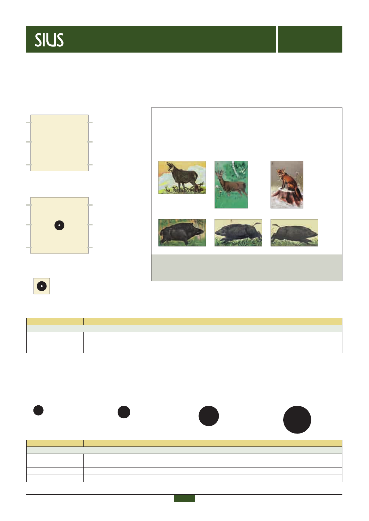
Circular target pictures
3 S150AA015 Bulls eye Ø 20 cm
4 S150AA006 Bulls eye Ø 24 cm
5 S150AA008 Bulls eye Ø 40 cm
6 S150AA009 Bulls eye Ø 60 cm
Circular target pictures
Circular target pictures can be used as well > mounting on basic multi wall panel = according to the center of measurement (see
page 2).
4 Bulls eye Ø 24cm 5 Bulls eye Ø 40cm 5 Bulls eye Ø 60cm3 Bulls eye Ø 20cm
Ordering hunting pictures:
– German Hunting Federation DJV > www.jagdverband.de
– Kuert Druck AG > www.kuert.ch (only within Switzerland)
Target front masks with hunting pictures
To mount the target front masks with hunting pictures, the basic multi wall panel for hunting pictures S110AA022 must be used. It
will be mounted on the wooden frame with Velcro fasteners.
Pos. Article no. Description
Basic multi wall panel for hunting pictures and calibrating target for telescopic sight
1 S110AA022 Basic multi wall panel for hunting pictures, 117x113,5cm
2 S110AA036 Multi wall panel, 117x113,5cm, with front mask of calibrating target Ø 20 cm
2.1 S150JVZA001 Center patch of calibrating target Ø 20 cm on top foil, 30x30cm
2 Calibrating target for telescopic sights
Even the single center patch for the calibration of telescopic sights is available.
It is glued on the basic multi wall panel according to manual «B072 S110_Jagdbilder_Montage_de/en».
1 Basic multi wall panel
for hunting pictures
Chamois DJV4 Roebuck DJV1 Fox DJV3
Wild boar DJV5Wild boar DJV2 Wild boar DJV7
The hunting pictures chamois, roebuck, fox and wild boar (3 versions)
must be ordered directly from:
German Hunting Federation DJV or Kuert Druck AG.
The adhesive hunting pictures can be mounted on the basic multi wall
panel according to manual «B072 S110_Jagdbilder_Montage_de/en».
2.1 Center patch of calibrating target for telescopic sights
11
Electronic scoring systems
B-INWA- AC13-en – 04/19
AC13
Open system for
supersonic
ammunition
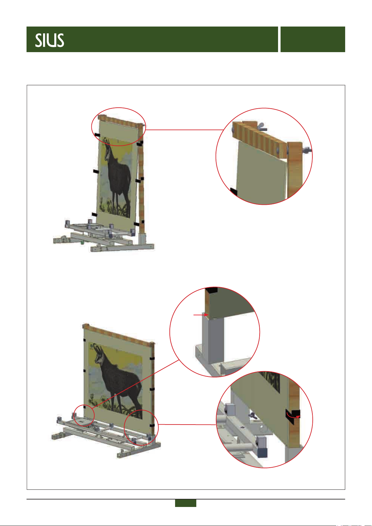
The multi wall panel must be attached
with the provided Velcro fasteners
Mounting of basic multi wall panel with target front mask
Placement of basic multi wall panel above: ush with the target frame
Mounting of basic multi wall panel with target front mask
Placement of basic multi wall panel below: ush with the holders
Installation

12
Electronic scoring systems
B-INWA- AC13-en – 04/19
AC13
Open system for
supersonic
ammunition
Mounting of protection plates
Mounting of protection plate sheet steel SPU12AN001
without debris protection SPU12AN004
Mounting of protection plate sheet steel SPU12AN001
and debris protection SPU12AN004
Mounting of protection plates
Placement according to the illustration below.
The protection plate and the debris protection are placed according to the illustration below.
Installation
Overview with mounted protection plate and debris protection.
The screws are placed in the more forward holes.
The screws are placed in the more backward holes.

13
Electronic scoring systems
B-INWA- AC13-en – 04/19
AC13
Open system for
supersonic
ammunition
Accessories: feet, wheel casters, oor mounts
Tilt foot SHS04AN001 Wheel caster Ø 80mm SHS07AN001
Floor xation temporarily SHS04AN005 Floor xation permanently SHS04AN006
Accessories: feet, wheel casters, oor mounts
set with 4 pieces set with 4 pieces
(2x with brake / 2x without brake)
set with 2 pieces set with 2 pieces
Installation
Mounting of tilt foot.
Mounting of wheel casters.
Mounted tilt foot.
Wheels in front with brake
Mounted wheel casters.
Installation of oor mounts. Installation of oor mounts.

14
Electronic scoring systems
B-INWA- AC13-en – 04/19
AC13
Open system for
supersonic
ammunition
Accessories: feet, wheel casters, oor mounts
Permanent xation on stable ground
Temporary xation on loose ground
Accessories: feet, wheel casters, oor mounts
The system is xed to the ground with screws and dowels.
The system is xed to the ground with bended iron bars or herrings.
Height adjustable legs SPU12AN005
The legs are mounted according to the illustration. The height can be adjusted individually.
This enables even a placement on uneven ground.
Installation
15
Electronic scoring systems
B-INWA- AC13-en – 04/19
AC13
Open system for
supersonic
ammunition
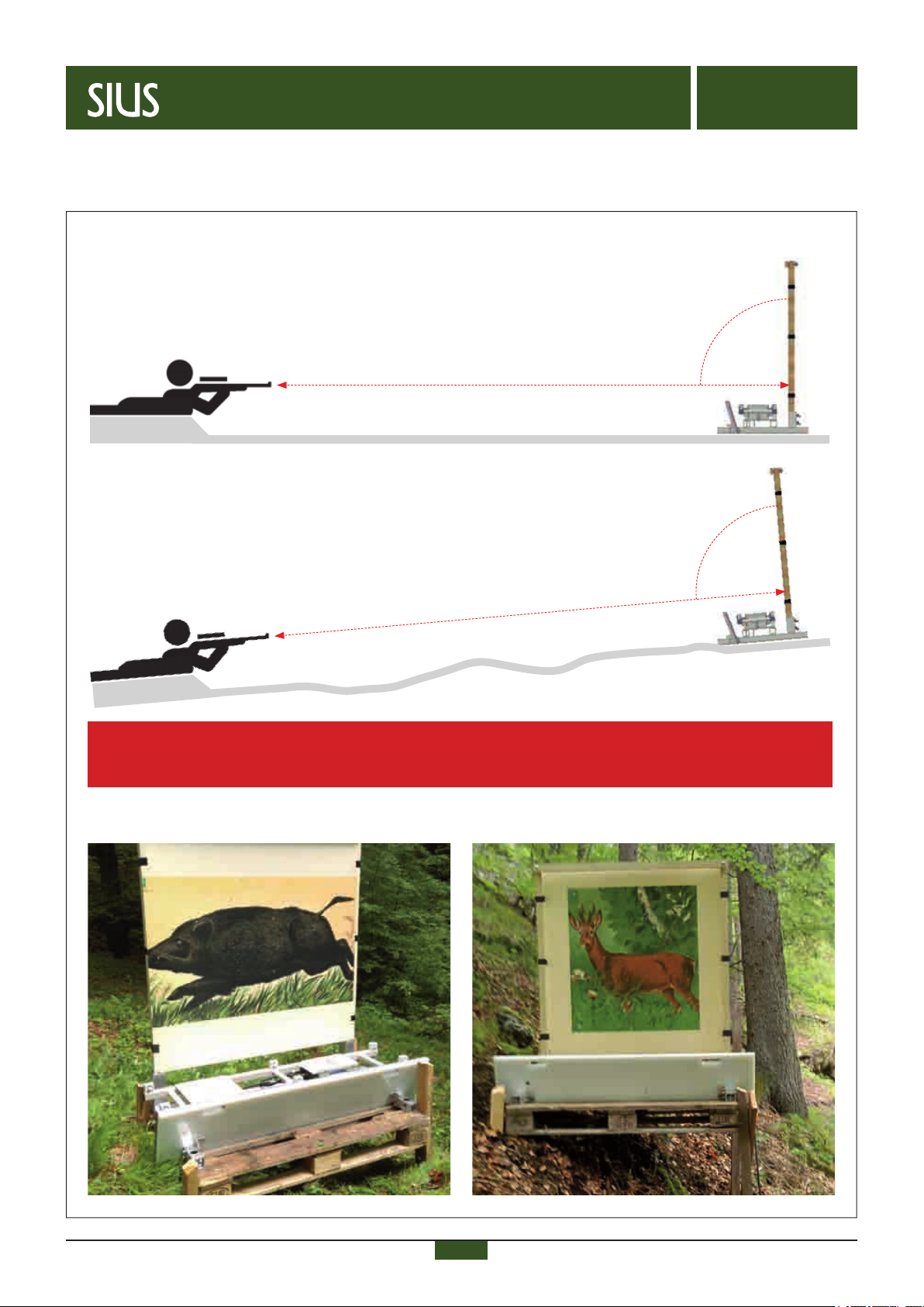
Positioning
Angle and distance to the shooter
• The target must be at a 90° angle to the shooter.
• Lateral shooting angle of max. 10°.
• The distance between shooter and target can be from 35m up to 1200m.
Example on even ground:
35 – 1200m
90°
Target
Example on ascending uneven ground:
35 – 1200m
90°
Target
Start-up the system
Positioning
Example of an installation and positioning with wooden pallet:
Tip for adjustment in a 90° angle: put a wooden lath on the two microphones in the middle (back–front). Target the ring point by
looking from behind over the wooden lath. The system is properly adjusted, if the ring and the vanishing point are in the same
position. This operation should be done without mounted target and protection plates.
Start-up
16
Electronic scoring systems
B-INWA- AC13-en – 04/19
AC13
Open system for
supersonic
ammunition
Start-up
Check in advance
All devices installed according to the instructions?
Any visible damages on devices or cables?
Voltage of the power supplies set according to the voltage of the electric power supply?
Set the lane no. on LNR-box, target line
Connecting to the electricity network Conguration of control unit
With control unit M95
With PC/Laptop and software SIUSLANE
The lane no. is set by turning the arrow on the number plate to
the corresponding numeral, using a screwdriver.
Connect all devices to the electricity network. The control unit (M95 or PC/Laptop with LON-dongle and software
SIUSLANE)
can be congured.
Relevant documents are available on the SIUS website.
Bringing into service of a system with connection via cable
System with connection via cable

17
Electronic scoring systems
B-INWA- AC13-en – 04/19
AC13
Open system for
supersonic
ammunition
Start-up
Check in advance
– All devices installed according to the instructions?
– Any visible damages on devices or cables?
– Are the batteries charged?
Start-up of a system with connection via radio
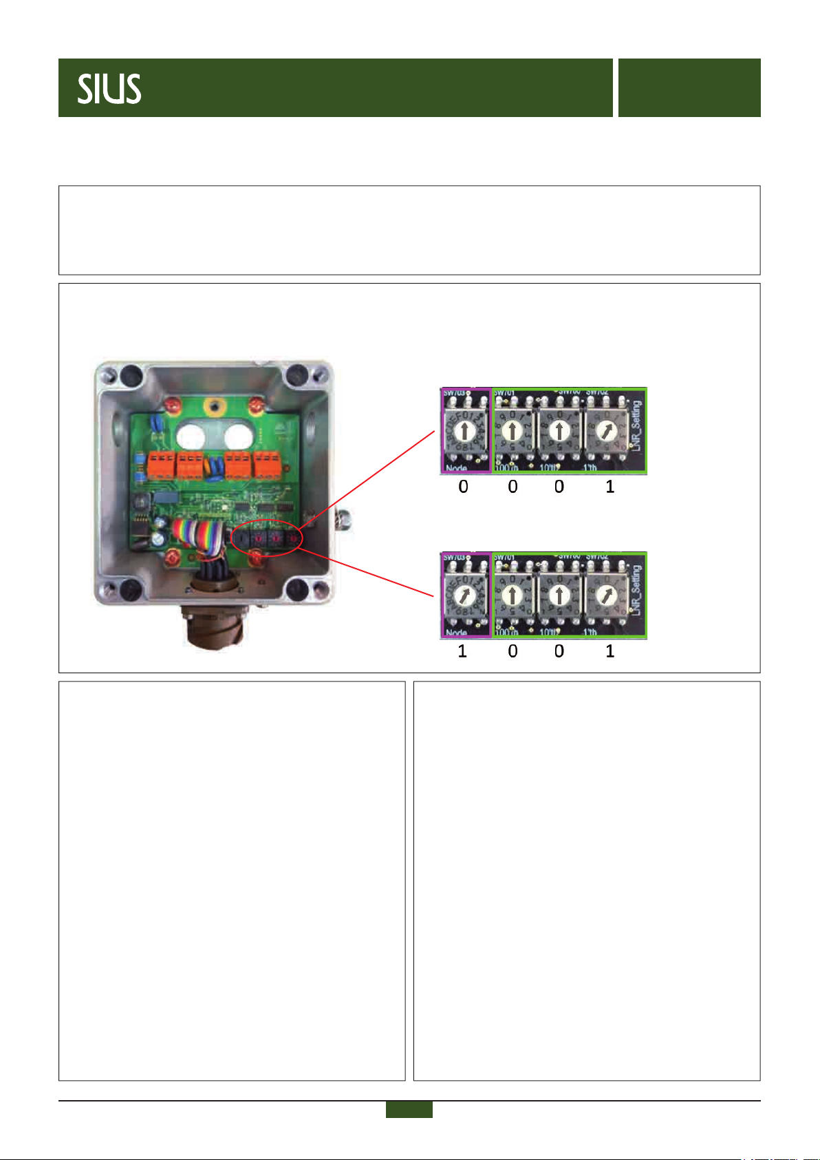
Set the lane no. on RBLon, target line
Connecting to the electricity Conguration of control unit
The lane no. is set by turning the arrow on the number plate to
the corresponding numeral, using a screwdriver.
Set switches into the shown position.
Connect the devices to the batteries. Turn the batteries on (toggle
switch > ON).
The control unit (M95 or PC/Laptop with LON-dongle and software
SIUSLANE)
can be congured.
Relevant documents are available on the SIUS website.
System with connection via radio
RBLon target line
RBLon ring line
( 0 0
0 1 (in combination with M95)
( 1 0
0 1 (in combination with PC/Laptop)
Radio channels
18
Electronic scoring systems
B-INWA- AC13-en – 04/19
AC13
Open system for
supersonic
ammunition
Maintenance and function control
Maintenance and function control (general)
Cleaning
– Clean the detection system AC13 if it is badly soiled.
– Clean the microphones with a soft damp cloth (do not use any cleaning agent).
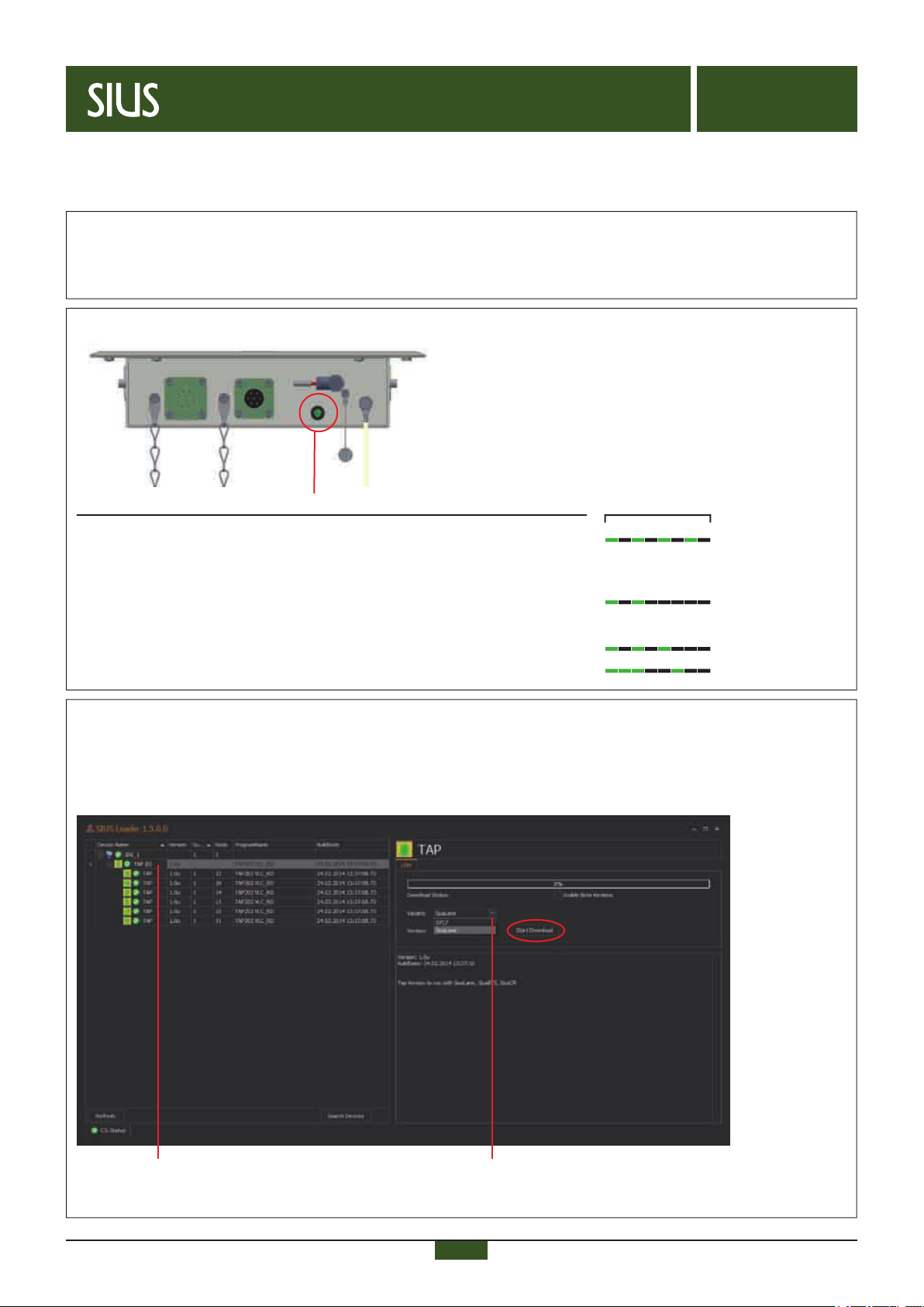
LED display of detection system AC13
LED operating status lights up permanently in green on readiness
for operation.
Faults are displayed by a corresponding ash code.
Faults
PSC voltage indicator
Power is below/exceeded.
Reason: cable connection to power supply is too long resp. battery is not sufciently charged.
Activation of microphones
As soon as a microphones is activated, the following ash code will be displayed (3x).
Technical faults
A technical fault is displayed by the following ash codes.
Flash code (2 sec.)
Software of detection system AC13
The detection system AC13 needs different software, if used whether with a control unit M95 or a PC/Laptop with software SIUSLANE.
The software is preinstalled.
If it is not possible to bring the system into service even after checking power supply, cables and settings, the software SIUSLOADER
enables a new software installation.
Software TAP Choice of the variant for:
SIUSLANE resp. System 7

19
Electronic scoring systems
B-INWA- AC13-en – 04/19
AC13
Open system for
supersonic
ammunition
RBLon target line:
• Power (illuminated) = unit is energized
• Watchdog (ashes) = software running
• In Range (illuminated)
• Bad/Good/Excellent (all 3 LED’s illuminated)
RBLon ring line:
• Power (illuminated) = unit is energized
• Watchdog (ashes) = software running
• In Range (illuminated) = connection to RBLon target line
• Bad/Good/Excellent (illuminated) = shows signal strength
Maintenance and function control
Maintenance and function control (connection via radio)
➊ ➋
LED display battery LED display RBLon
The ash code of the LED indicates the status of the battery.
The color shows, how much the battery is charged.
If the battery is not in use for a longer period of time, it should be
disconnected. Charge it at least once per calendar quarter.
Flash code (1 sec.)
Status
Standby
On
Charge
Red = battery low
Yellow = battery medium
Green = Battery good

20
Electronic scoring systems
B-INWA- AC13-en – 04/19
AC13
Open system for
supersonic
ammunition
SIUS worldwide
There are SIUS representatives all around the globe.
Find your local SIUS sales partner here:
www.sius.com > contact
Popular Industrial Equipment manuals by other brands

ABB
ABB HT578503 Operation manual

CS Instruments
CS Instruments VA 500 Mounting instruction

Spirax Sarco
Spirax Sarco AE50S Installation and maintenance instructions

Powertrain
Powertrain WALTERSCHEID EK62/2S-L Repair instructions

ABB
ABB HT575013 Operation manual

Afag
Afag UG 20 Series Montage & maintenance Instructions


