Afag UG 20 Series Manual

Universal Gripper
UG 20, UG 25
- Declaration of Incorporation
- Module Information
- Montage Instructions
- Maintenance Instructions
„Translation“ of the Original Montage Instructions
© copyright by Afag Automation AG

2 UG 20-UG 25-OI-vers. 3.5 gb. 20190409
These Montage Instructions apply to:
Type Order No. Type Order No.
UG 20 NN 50032661 UG 25 NN 50030771
UG 20 NC 50032663 UG 25 NC 50030772
UG 20 NO 50032664 UG 25 NO 50030773
Version of this documentation: UG 20-UG 25-OI-vers. 3.5 gb. 20190409
Symbols: Assembly and initial start-up must be
carried out by qualified personnel only
and according to these Montage
Instructions.
DANGER
Indicates an immediate threatening danger.
Non-compliance with this information can result in death or
serious personal injuries (invalidity).
WARNING
Indicates a possible dangerous situation.
Non-compliance with this information can result in death or
serious personal injuries (invalidity).
CAUTION
Indicates a possibly dangerous situation.
Non-compliance with this information can result in damage to
property or light to medium personal injuries.
NOTE
Indicates general notes, useful operator tips and operating
recommendations which don't affect safety and health of the
personnel.

UG 20-UG 25-OI-vers. 3.5 gb. 20190409 3
Table of contents
Table of contents ........................................................................................................ 3
1.0.0 EC Declaration for Incorporation (Document original) ....................................... 5
1.1.0 According to: 2006/42/EG .............................................................................. 5
2.0.0 Module Information ............................................................................................ 6
2.1.0 Transport and storage (packing and unpacking) ............................................ 6
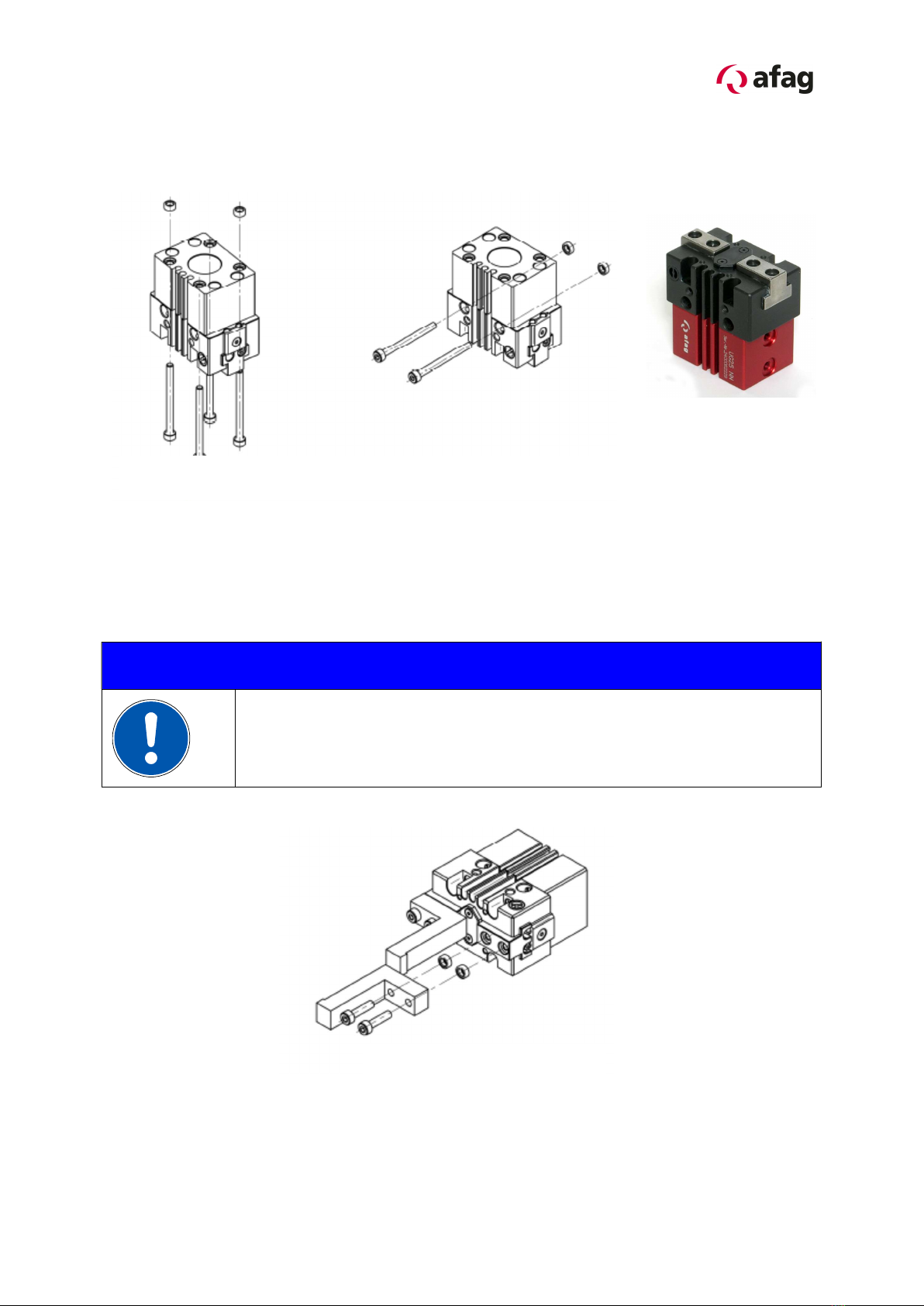
2.1.1 Assembly for the gripper ................................................................................ 7
2.1.2 Mounting for the gripper finger ....................................................................... 7
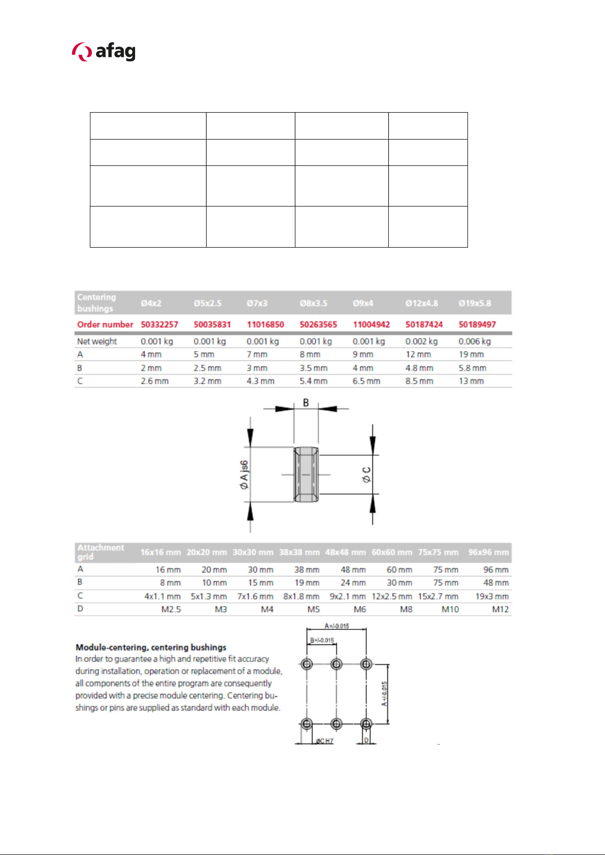
2.1.3 Hole matrix and centering bushings ............................................................... 8
2.1.4 Tightening torques for bolts ............................................................................ 9
3.0.0 Montage Instructions (Document original) ....................................................... 10
3.1.0 Manufacturer address: ................................................................................. 10
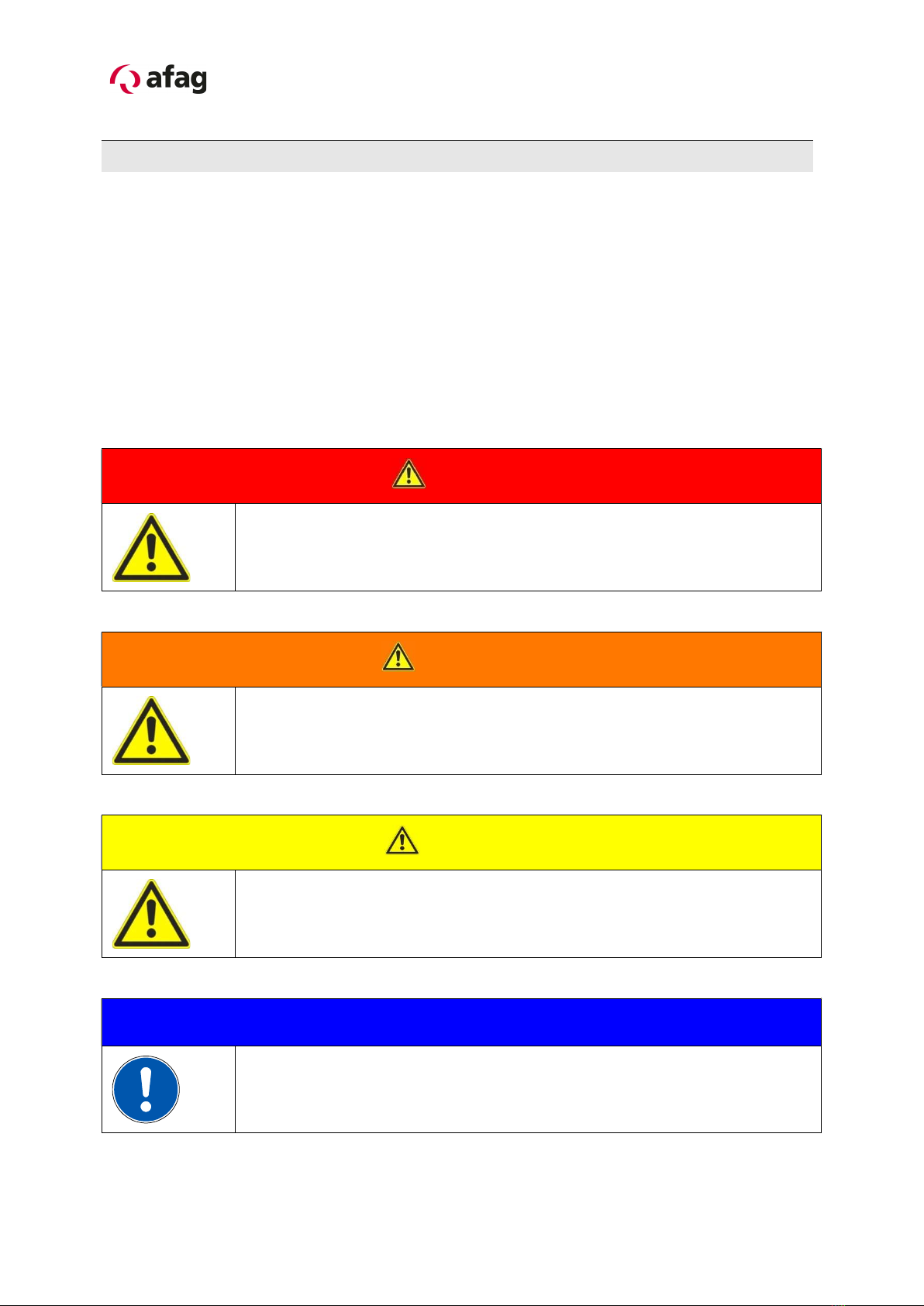
3.1.1 Symbols ....................................................................................................... 11
3.1.2 General description ...................................................................................... 11
3.1.3 General description for the module UG 20 / UG 25 ..................................... 12
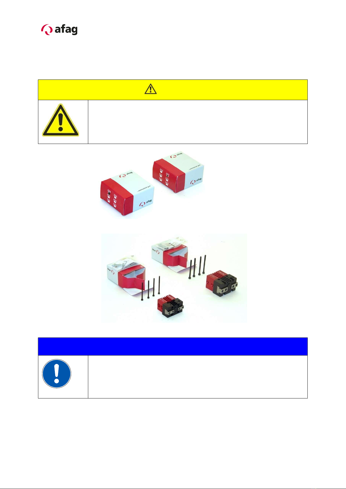
3.1.4 Scope of supply ........................................................................................... 13
3.1.5 Guarantee .................................................................................................... 14
3.1.6 Areas of application ...................................................................................... 14
3.1.7 Dimensions drawing UG 20 ......................................................................... 15
3.1.8 Technical data of the UG 20 ........................................................................ 16
3.1.9 Preferred combinations UG 20 ..................................................................... 17
3.2.0 Module stresses UG 20 ................................................................................ 18
3.2.1 Dimensions drawing UG 25 ......................................................................... 20
3.2.2 Technical data of the UG 25 ........................................................................ 21
3.2.3 Preferred combinations UG 25 ..................................................................... 22
3.2.4 Module stresses UG 25 ................................................................................ 23
3.2.5 Pneumatic connection for the UG-Universal gripper .................................... 25
3.2.6 Preparation for Commissioning .................................................................... 26
3.2.7 Fitting the proximity switch in the module grooves ....................................... 27
3.2.8 Example of application of sensor technology combined with specially formed
grip fingers (depending on application): ................................................................ 28

4 UG 20-UG 25-OI-vers. 3.5 gb. 20190409
4.0.0 Maintenance instructions ................................................................................. 29
4.1.0 Maintenance and servicing of the UG 20/25 Universal gripper .................... 29
4.1.1 Servicing ...................................................................................................... 30
4.1.2 Accessories the UG 20 / UG 25 ................................................................... 31
4.1.3 Trouble-shooting .......................................................................................... 31
4.1.4 Disassembly and repair ................................................................................ 32
5.0.0 Disposal ........................................................................................................... 33

UG 20-UG 25-OI-vers. 3.5 gb. 20190409 5
1.0.0 EC Declaration for Incorporation (Document original)
1.1.0 According to: 2006/42/EG
Standard: EN ISO 12100:2010 (German Version)
The manufacturer:
Afag Automation AG, Fiechtenstrasse 32, CH-4950 Huttwil
hereby declares that the incomplete machine:
Producte name: Universal gripper (pneumatic)
Types: UG 20 / UG 25
Sequential series No. 50xxxxxx
Relevant EC Machinery Directive:
Machinery Directive: 2006/42/EC
Standard: EN ISO 12100:2010 (German Version)
- Safety of machinery General principles for risk assessment and risk reduction.
- The special technical documents shall be sent to a reasoned request by national
authorities in printed documents or electronically (pdf).
Applied and fulfilled essential requirements:
1.1; 1.1.1; 1.1.2; 1.2.3; 1.2.4.4; 1.3; 1.3.5; 1.3.6; 1.3.7; 1.3.9; 1.4.1; 1.5; 1.5.3; 1.6;
1.6.1; 1.6.3; 1.6.4; 1.7; 1.7.4; 1.7.4.1; 1.7.4.2
Who installs this incomplete machine or assemble with other machines, a risk
assessment for its resulting machine which must make the provisions of the
EC directive: 2006/42 /EC
Norme: EN ISO 12100:2010 (German Version)
Agent:
For the compilation of the technically relevant documents:
Niklaus Röthlisberger, Producte Manager Afag Automation AG, CH-4950 Huttwil
Place, Date: Huttwil, 09. 04. 2019
Siegfried Egli Niklaus Röthlisberger
Managing Director Producte Manager HT
Afag Automation AG Afag Automation AG

6 UG 20-UG 25-OI-vers. 3.5 gb. 20190409
2.0.0 Module Information
2.1.0 Transport and storage (packing and unpacking)
CAUTION
The UG Universal gripper is packed in the original cardboard
box; if the module is not handled properly it may fall out of the
box when unpacking and cause injuries to limbs or squeeze
your fingers.
NOTE
Technical specification the safety information.
This information sheet must be read and applied by any person
change of carring out work with and on this module
pneumatic/electrical.

UG 20-UG 25-OI-vers. 3.5 gb. 20190409 7
2.1.1 Assembly for the gripper
Depending on the application the gripper can be attached from the side or from
below:
Use the centering bushings included in the scope of supply to determine the position.
2.1.2 Mounting for the gripper finger
NOTE
Further elements to be mounted can be attached to the fastening
threads for the holding-down device.
(see chapter Description)
Installation from below
Installation from the side
Fitting of grip fingers

8 UG 20-UG 25-OI-vers. 3.5 gb. 20190409
2.1.3 Hole matrix and centering bushings
Hole matrix at the UG 20 / UG 25 Universal gripper
UG 20 UG 25
Hole matrix 20x20mm Hole matrix 30x30mm
Thread / bore hole M3 Thread/bore
hole
M4
Centering
bushings (H7)
Ø 5x2.5mm Centering
bushings
Ø 7x3mm
Use the centering bushings included in the scope of supply for positioning and insert
these sleeves in the diagonally opposite bore holes of the mounting grid.

UG 20-UG 25-OI-vers. 3.5 gb. 20190409 9
2.1.4 Tightening torques for bolts
The screws to be used for assembly must at least satisfy the following conditions:
Standard: VDI 2230
Strength: class 8.8
Surface: galvanized blue, oiled or greased
Thread Tightening moments
M3 1,1 … 1,4 Nm
M4 2,6 … 3,3 Nm
M5 5,2 … 6,5 Nm
M6 9,0 ... 11,3 Nm
M8 21,6 … 27,3 Nm
This is an incomplete machine
Assembly of the UG Universal gripper in a system
The series of the UG Universal gripper is used for the linear, smooth movement of
rigidly mounted loads under the ambient and Installation conditions defined for this
module, see Technical data. The UG Universal gripper can be installed in the
horizontal or vertical position.
NOTE
These Montage Instructions should be read carefully before carrying
out any activity on or with the UG Universal gripper. The UG
Universal gripper may only be deployed in accordance with the
intended use.
NOTE
Safety instructions
Modifications on the UG Universal gripper that are not described in
these Montage Instructions or have not been approved in writing by
Afag Automation AG are not permitted. In case of improper changes
or assembly, installation, operation and maintenance or repairs Afag
rejects all liability.

10 UG 20-UG 25-OI-vers. 3.5 gb. 20190409
3.0.0 Montage Instructions (Document original)
3.1.0 Manufacturer address:
Afag Automation AG
Fiechtenstrasse 32
CH-4950 Huttwil
Sales Handling:
Tel. 0041 (0)62 959 87 02
www.afag.com
These operating instructions apply to:
Producte name: UG – Universal gripper (pneumatic)
Types: UG 20 and UG 25
Sequential series: No. 50xxxxxx
This is an incomplete machine
Who installs this incomplete machine or assemble with other machines, a risk
assessment for its resulting machine which must make the provisions of the
EC directive: 2006/42/EC
Standard: EN ISO 12100:2010 (German version)
Agent:
For the compilation of the technically relevant documents:
Niklaus Röthlisberger, Products Manager Afag Automation AG, CH-4950 Huttwil

UG 20-UG 25-OI-vers. 3.5 gb. 20190409 11
3.1.1 Symbols
Assembly and initial start-up must be carried out by qualified personnel only and
according to these instructions.
CAUTION
Indicates a possibly dangerous situation.
Non-compliance with this information can result in damage to
property or light to medium personal injuries.
NOTE
Indicates general notes, useful operator tips and Installation
recommendations which don't affect safety and health of the
personnel.
3.1.2 General description
The series of the UG 20/25 Universal gripper is used for the linear, smooth
movement of rigidly mounted loads under the ambient and Installation conditions
defined, see Technical data.
The UG 20/25 Universal gripper can be installed in the horizontal or vertical position.
Modifications on the UG 20/25 Universal gripper that are not described in these
Montage Instructions or have not been approved in writing by Afag Automation AG
are not permitted. In case of improper changes or assembly, installation, operation,
maintenance or repairs, Afag Automation AG rejects all liability.

12 UG 20-UG 25-OI-vers. 3.5 gb. 20190409
3.1.3 General description for the module UG 20 / UG 25
1 Cylinder casing 7 Cover of fastening screws
2 Jaw casing 8 Side mounting holes
3 Grip jaws 9 Top Mounting holes
4 C-grooves for magnetic sensors 10 Fastening thread of holding-down
device
5 Holder for inductive sensors 11 Cover plate of grip mechanism
6 Set screws of stroke detection 12 Pneumatic connections
The grippers UG 20 and UG 25 consist of the cylinder casing (1) and the jaw casing
(2). The two casings are firmly connected with each other and cannot be separated.
The pneumatic cylinder (1) which transmits its movements to the grip jaws (3) via two
reversing levers operates in the pneumatic cylinder. The grip jaws (3) move parallel
with each other. The grip mechanism is protected from dirt and dust by the cover
plate (11).
The grippers are available as type NN (without spring preload), NC (pressureless,
closed) and NO (pressureless, open). They change of design is not possible.
To query the gripping positions and depending on the requirement up to three
magnetic sensors (accessories) as well as up to two inductive sensors (accessories)
can be installed either in the C-grooves (4) or in the holder (5). Thus the gripper can
check up to 5 positions.
One possible application is the query „Gripper open“, „Gripper closed“ and „Part
gripped“. When positive grip fingers and asymmetric parts are used it is also possible
to check whether the part is held in the correct position in the gripper.
The inductive sensors are covered by the set screws (6). Loosen the fastening
screws under the cover (7) to adjust the set screws (6) and then retighten the
fastening screws.
The 4 threads (10) can be used to install holding-down devices or similar add-on
parts.
2
1
5
12
4
3 7
8
6
9
7
10 11

UG 20-UG 25-OI-vers. 3.5 gb. 20190409 13
3.1.4 Scope of supply
Quantity
Description
1
Module
2
Centering bushings Ø 5x2.5 mm (UG 20)
2
2
4
2
Centering bushings Ø 7x3 mm (UG 25)
Mounting screw M3x30 mm (UG 20)
Mounting screw M3x50 mm (UG 20)
Mounting screw M4x35 mm
(UG 25)
4
Mounting screw M4x55 mm (UG 25)
Intended use
The series of the UG Universal gripper is used for the linear movement of rigidly
mounted loads under the ambient and Installation conditions defined for this module;
see Technical catalogue.
NOTE
These Montage Instructions should be read carefully before carrying
out any activity on or with the module.
The module may only be deployed in accordance with the intended
use.
Modifications on the module that are not described in these Montage
Instructions or have not been approved in writing by Afag are not
permitted. In case of improper changes or assembly, installation,
operation, maintenance or repairs, Afag rejects all liability.
CAUTION
Connection of compressed air and operation of pneumatic
systems may cause unpredictable movements which may result
in personal injury or damage to property.
When connecting compressed air for the first time make sure that all air throttles are
closed. Aerate the system slowly.

14 UG 20-UG 25-OI-vers. 3.5 gb. 20190409
3.1.5 Guarantee
3.1.6 Areas of application
The UG 20/25 are exclusively designed for the gripper movement of load capacities
of up to UG 20 gripping forces open178 N (closed 150 N); UG 25 gripping forces
open 334 N, (closed 300 N).They can also be used in combination with other
modules than Pick &Place machines, and allowed gripping forces may not become
exceeded.
Any other use is regarded as inadequate.
NOTE
The manufacturer does not accept any liability for damage
resulting from such use. The risk is that of the user alone.
Intended use also includes paying attention to the Montage Instructions and
observing the maintenance and repair instructions specified by the manufacturer.
The UG Universal gripper may only be operated and serviced by correspondingly
trained personnel who have also profound knowledge of the dangers.
CAUTION
The applicable regulations for prevention of accidents and the
other generally accepted safety-relevant and occupational
safety and health regulations are to be followed.
The term of the warranty on Afag handling components and systems is:
24 months following commissioning, but a maximum of 27 months following delivery.
Wear parts (e.g. shock absorbers) are not covered by the warranty. *
The warranty covers the replacement or repair of defective Afag parts. No further claims will be
accepted.
The warranty will be voided in event of the following:
Use for other than the intended purpose
Failure to observe the notes on installation, commissioning, operation and maintenance in
the operating manual
Improper installation, commissioning, operation and maintenance
Independent repairs and constructional changes without prior instruction by Afag
Automation AG
Removal of the serial number on the product
Using the module without shock absorbers, or with defective shock absorbers
Inadequate monitoring of wear parts
*A customer has the right to a defect-free product. This is also applicable for accessories and wear parts, if they are
defective.
However, wear does not fall within the scope of the warranty.

UG 20-UG 25-OI-vers. 3.5 gb. 20190409 15
3.1.7 Dimensions drawing UG 20

16 UG 20-UG 25-OI-vers. 3.5 gb. 20190409
3.1.8 Technical data of the UG 20

UG 20-UG 25-OI-vers. 3.5 gb. 20190409 17
3.1.9 Preferred combinations UG 20

18 UG 20-UG 25-OI-vers. 3.5 gb. 20190409
3.2.0 Module stresses UG 20

UG 20-UG 25-OI-vers. 3.5 gb. 20190409 19

20 UG 20-UG 25-OI-vers. 3.5 gb. 20190409
3.2.1 Dimensions drawing UG 25
Other manuals for UG 20 Series
1
This manual suits for next models
7
Table of contents
Other Afag Industrial Equipment manuals

Afag
Afag aflex 150 Installation instructions

Afag
Afag DG 16-W Quick reference guide

Afag
Afag CS 8/10-SD User manual

Afag
Afag EU-20 User manual

Afag
Afag EPS mini YZ User manual

Afag
Afag HLF07-P Product guide

Afag
Afag CR 16-D Quick reference guide

Afag
Afag IBB3.5 User manual

Afag
Afag SA-3 Series User manual

Afag
Afag CS 25 Series Manual