Unipart Dorman HD ALT User manual

Heavy Duty Assisted Lift Trunnion
Operation and Maintenance Manual
C64.65546
Issue 5
May 2021

Heavy Duty Assisted Lift Trunnion Operation and Maintenance Manual Form Reference C64.65546
Issue 5.00
1 of 39 Issue Date May 2021
Table of Contents
Document Control ....................................................................................................................... 2
Introduction ................................................................................................................................ 4
Product Labelling ........................................................................................................................ 5
Safety .......................................................................................................................................... 6
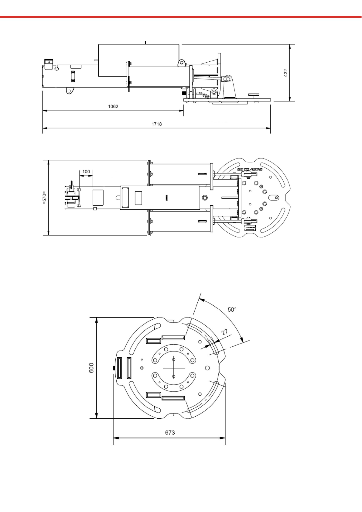
Dimensions .................................................................................................................................. 8
Description ................................................................................................................................ 10
Signal Configuration and Lifting Data ...................................................................................... 10
Storage and Movement ............................................................................................................. 12
Tooling ....................................................................................................................................... 13
Torque Loadings ........................................................................................................................ 13
Foundation and Site Checks ..................................................................................................... 14
Pre Installation Checks ............................................................................................................. 15
Installation ................................................................................................................................ 16
Raising &Lowering the HD ALT ................................................................................................ 17
Inserting the Post and Erecting the Signal .............................................................................. 18
Electrical Connection ................................................................................................................ 21
Signal Alignment ....................................................................................................................... 22
Post Installation Checks ........................................................................................................... 27
Module Replacement (CLS Module) ......................................................................................... 27
Module Replacement (Other Signal Modules) ......................................................................... 29
Additional Visors ....................................................................................................................... 30
Wedge Inserts ........................................................................................................................... 33
Blanking Plates ......................................................................................................................... 33
Maintenance Activity ................................................................................................................ 34
Signal Husbandry ...................................................................................................................... 34
Service and Repair .................................................................................................................... 35
End of Life Disposal ................................................................................................................... 35
Product Support ........................................................................................................................ 35
Appendix A - HD ALT/Signal Lifting Force Data ...................................................................... 35

Heavy Duty Assisted Lift Trunnion Operation and Maintenance Manual Form Reference C64.65546
Issue 5.00
2 of 39 Issue Date May 2021
Document Control
It is the reader’s responsibility to ensure they have the correct version of this document. If in
doubt, please contact Unipart Dorman to verify the current issue status.
Issue Number
Dated
Reason
1
Jul 19
Initial Issue
2 Sep 19 References to RBK-221 padlock added
3 Nov 19 Images and layout updated following feedback
from Network Rail PA review.
4 Jan 20 Wording changes following Network Rail Product
Acceptance and Ergonomics Review
5 May 21
Additional Safety Warnings
Addition of extra information on signal alignment
methods
New section on Module Replacement
Name
Role
Digital Signature
Author Graham Scott Technical Sales Manager
Checked by Mike Durham Design and Development
Engineer
Approved by John Lee Head of Design and
Development
Graham
Scott
Digitally signed by Graham Scott
DN: dc=local, dc=unipartrail,
ou=Southport, ou=Departments,
ou=Technical Sales, cn=Graham Scott,
Date: 2021.06.03 15:00:21 +01'00'
Digitally signed
by: Mike Durham
Date: 2021.06.03
15:18:33 Z
Mike
Durham
Digitally signed by: John Lee
DN: CN = John Lee email =
= Southport, Departments,
Technical
Date: 2021.06.03 15:27:21 Z
John Lee

Heavy Duty Assisted Lift Trunnion Operation and Maintenance Manual Form Reference C64.65546
Issue 5.00
3 of 39 Issue Date May 2021
Safety Warning
THE UNIPART DORMAN HEAVY DUTY ASSISTED LIFT TRUNNION (HD
ALT) UTILISES TWO SPRING ASSEMBLIES TO PROVIDE ASISTANCE
WHEN RAISING AND LOWERING THE SIGNAL BY HAND
WHEN THE HD ALT IS IN THE HORIZONTAL POSITION KINETIC ENERGY
IS STORED IN THE SPRINGS AND TO PREVENT RAPID DEPLOYMENT OF
THIS, A SUITABLE HEAD AND POST SHALL BE FITTED TO PROVIDE A
BALANCING LOAD TO COUNTER THE SPRING FORCE BEFORE ANY
ATTEMPT TO RAISE THE UNIT INTO ITS VERTICAL STATE
DO NOT REMOVE THE PADLOCK/SAFETY PINS UNTIL
THE HEAD AND POST ARE FITTED AND SUFFICIENT
STAFF ARE AVAILABLE TO CONTROL THE SIGNAL AS IT
RISES TO THE VERTICAL POSITION
THERE ARE NO USER MAINTAINABLE PARTS ON THE HD ALT
ANY ATTEMPT TO DISASSEMBLE THE SPRING UNITS OR FULCRUM ARMS
COULD RESULT IN CATASTROPHIC RELEASE OF THE STORED SPRING
ENERGY WHICH WILL PRESENT CONSIDERABLE RISK OF INJURY OR
ENDANGER LIFE

Heavy Duty Assisted Lift Trunnion Operation and Maintenance Manual Form Reference C64.65546
Issue 5.00
4 of 39 Issue Date May 2021
Introduction
The Unipart Dorman Heavy Duty Assisted Lift Trunnion (HD ALT) uses twin reactive springs
controlled by a fulcrum system that allows the force required to move the signal post from the
horizontal to vertical to be equalised across the full range of movement. This means that it can
be raised and lowered by hand without any additional mechanical handling equipment.
HD ALT is designed to interface with only Unipart Dorman Lightweight and CLS LITE Signals as
shown in the product configuration drawing C64.65378. Additionally, the HD ALT can be used
to mount a variety of Classic Signals & Indicators and level crossing Road Traffic Lights
(Wigwags) using the brackets detailed in the Network Rail Product Acceptance Certificate
PA05/06503.
A separate document will cover the Offset post when used in HD ALT
The complete signal can be quickly installed onto a standard foundation or screw pile system
set with 4 x M24 studs at 380mm centres as shown in Network Rail Drawing BRS-C-45. These
studs should have a MINIMUM of 200mm threaded section available above the top face of the
foundation.
Although the HD ALT was developed from and shares many similarities with the Standard ALT,
they are entirely separate products with distinctive operation and safety properties. Any
acquired knowledge of the Standard ALT shall not be used as a cross reference to the HD ALT.
Separate O&M Manuals and Product Awareness Sessions are available for both Trunnions and
these are available from Unipart Dorman.

Heavy Duty Assisted Lift Trunnion Operation and Maintenance Manual Form Reference C64.65546
Issue 5.00
5 of 39 Issue Date May 2021
Product Labelling
The following labels are applied to each HD ALT
The RBK-211 padlock is not shown in this illustration for clarity

Heavy Duty Assisted Lift Trunnion Operation and Maintenance Manual Form Reference C64.65546
Issue 5.00
6 of 39 Issue Date May 2021
Safety
Activities, which may pose a hazard, will have the following highlighters:
Activities identified as needing extra care are highlighted using the Caution Symbol
ACTIVITIES WHICH ARE OR HAVE THE POTENTIAL TO BE HAZARDOUS TO
PERSONNEL AND/OR EQUIPMENT ARE HIGHLIGHTED WITH THE WARNING SYMBOL
BEFORE THE COMMENCEMENT OF ANY ACTIVITY, ARRANGEMENTS SHALL BE
APPLIED TO PROTECT THE WORKING RAILWAY.
It is the user’s responsibility to ensure all necessary risk assessments, permissions to work and
preparatory safety activities are correctly completed and adhered to throughout the installation
and subsequent life of the signal.
The Unipart Dorman HD ALT has been designed in accordance with the principles and methods
detailed in the Network Rail Design for Reliability Process and has been subjected to extensive
testing throughout its development to meet these requirements and subsequently obtain Network
Rail Product Acceptance.
This Operation and Maintenance document is designed to illustrate safe methods of work and
highlight potential dangers to workers. It is a generic guide only and the content is not to be used
to substitute or justify the omission of good engineering practices.
FAILURE TO ADHERE TO THE INSTRUCTIONS AND WARNINGS CONTAINED IN
THIS PUBLICATION COULD CAUSE SERIOUS INJURY, ENDANGER LIFE AND/OR
CAUSE CATASTROPHIC DAMAGE TO THE EQUIPMENT AND SURROUNDING
INFRASTRUCTURE.
The weight of the HD ALT (165Kg) is clearly marked and installers should ensure that they have
sufficient measures in place to ensure a safe lift. The marked weight is for the HD ALT only and
does not include any pallet or packaging weight.

Heavy Duty Assisted Lift Trunnion Operation and Maintenance Manual Form Reference C64.65546
Issue 5.00
7 of 39 Issue Date May 2021
To enable simple transport and installation the HD ALT is delivered from the factory locked in the
horizontal position using the lockdown safety pin secured with a standard RBK-221 Padlock.
DO NOT ATTEMPT TO REMOVE THE PADLOCK AND SAFETY PIN UNLESS A
SUITABLE HEAD/POST IS FITTED CORRECTLY INTO THE HD ALT
REMOVING THESE HOLD DOWN DEVICES WITHOUT THIS LOAD MAY CAUSE SERIOUS
INJURY AND ENDANGER LIFE DUE TO THE STORED ENERGY IN THE SPRING SYSTEM
BEING RAPIDLY RELEASED
The HD ALT shall not be used for any purpose other than that described in the introduction above.
If it is used for any other purpose, Unipart Dorman will not accept any responsibility for damage,
injury or death caused by the activity.
THERE ARE NO USER SERVICEABLE PARTS IN THE HD ALT AND ANY ATTEMPT
TO DISASSEMBLE THE SPRING UNITS MAY ENDANGER LIFE AND WILL VOID ANY
WARRANTY
All activity on the HD ALT and any associated head/post, both mechanical and electrical, must
only be carried out by staff deemed competent in these fields by their employer. It is the user’s
sole responsibility to ensure that the apparatus is installed and/or maintained by competent staff
in accordance with the latest policies published by Network Rail such as Noticeboards etc. Where
a specific competency is subject to periodic retest and certification, it should be valid throughout
the time of the works.
A copy of these instructions shall be readily available. Anyone required to operate the HD ALT is
to be fully conversant with them and deemed sufficiently competent (and where necessary,
properly certified) to undertake the task by their supervisory chain.
The latest version of this document is available from Unipart Dorman using the contact details
on the back page or by visiting the Unipart Dorman website.
Operating Safely
IF ANY DOUBT EXISTS ON THE SERVICEABILITY OF THE HD ALT, YOU ARE NOT SURE
ABOUT ANY OF THE INSTRUCTIONS IN THIS DOCUMENT OR YOU ARE UNSURE OF
THE CORRECT WAY TO USE THE HD ALT, YOU SHOULD STOP WORK AND CONTACT
YOUR SUPERVISOR IMMEDIATELY AND IF NECESSARY, UNIPART DORMAN FOR
SPECIALIST ADVICE USING THE DETAILS ON THE BACK PAGE

Heavy Duty Assisted Lift Trunnion Operation and Maintenance Manual Form Reference C64.65546
Issue 5.00
8 of 39 Issue Date May 2021
Dimensions

Heavy Duty Assisted Lift Trunnion Operation and Maintenance Manual Form Reference C64.65546
Issue 5.00
9 of 39 Issue Date May 2021

Heavy Duty Assisted Lift Trunnion Operation and Maintenance Manual Form Reference C64.65546
Issue 5.00
10 of 39 Issue Date May 2021
Description
The Unipart Dorman HD ALT is a device designed for use in the railway environment as a
means of erecting a signal and then forming the support structure for that signal. It is
constructed of two main sub-assemblies. The base plate, designed to suit a BRS-SC-45 footprint
and a tubular housing with two spring units attached connected by a main hinge. The main
tubular housing has a signal securing collar and electrical connection box as constituent parts.
The two sub-assemblies share mountings for the hold down pin and brackets. Lifting eyes are
provided for ease of transport and installation.
Once the signal head and post are inserted and the HD ALT is in its vertical position the two
sub-assemblies are secured together using 8 x M24 bolts and this action forms the main
mounting interface between the signal and the foundation.
When vertical, all spring force is dispersed and there is no stored energy in the unit.
Signal Configuration and Lifting Data
The HD ALT system will support a wide range of Unipart Dorman signal heads as shown in
Unipart Dorman drawing 0094/019441 which is available on the Unipart Dorman website.
The complete signal is available at varying heights as measured from the top of the railhead to
the centre of the most restrictive aspect and a further dimension from the top of the rail to the
top of the foundation. This data and the precise geographic location information is supplied by
the customer against a unique signal identifier.

Heavy Duty Assisted Lift Trunnion Operation and Maintenance Manual Form Reference C64.65546
Issue 5.00
11 of 39 Issue Date May 2021
Each individual signal dataset then undergoes a set of structural calculations to confirm it
complies with PAN/E/CE 0017 (Project Advice Note – Signal Structures – ‘Form A’ Guidance for
Loading and Performance’). This, together with the restrictions on signal head configurations
included within the generic F001, F002, and F003 submission, delivers a robust system that
mitigates the risk of the safe working load on the Signal Post and HD ALT Assembly being
exceeded.
Only if all of the deflection and safety calculations are within limits will a manufacturing, stress
and loading drawing be produced for final sign off by the customer. Manufacturing begins when
the signed drawing is received by Unipart Dorman.
The HD ALT spring system is designed to provide mechanical advantage to personnel engaged
in manually lifting or lowering the signal about the vertical position. To give some guidance on
the force required to operate the HD ALT system and consequently the
suggested
amount of
workers needed to complete the task safely, Unipart Dorman has produced a lifting force graph
as shown in Appendix A.
It is impossible to determine the site conditions, capability of the persons
engaged in the operation and other variables at each individual location.
Therefore, the data shown in the Appendix is solely provided to
assist
in the
formulation of individual site risk assessments and method statements etc.
Unipart Dorman does not accept any responsibility for misuse of this guidance data,
which subsequently causes injury or damage

Heavy Duty Assisted Lift Trunnion Operation and Maintenance Manual Form Reference C64.65546
Issue 5.00
12 of 39 Issue Date May 2021
Storage and Movement
THE HD ALT SHOULD BE STORED IN THE HORIZONTAL POSITION AT ALL TIMES,
SECURELY LOCKED DOWN WITH THE PIN AND PADLOCK.
ATTEMPTING TO MOVE THE UNIT TO THE VERTICAL POSITION WITHOUT A HEAD
AND POST INSTALLED, MAY CAUSE SERIOUS INJURY AND ENDANGER LIFE DUE TO
THE STORED ENERGY IN THE SPRING SYSTEM BEING RAPIDLY RELEASED
The HD ALT is supplied on a large pallet as shown below and may be stored in the open air. The
fasteners used to secure the unit to the pallet shall not be used as mounting hardware during
installation and all packaging materials when removed, should be disposed of in accordance with
local regulations.
It should be noted that the HD ALT weighs typically 165kg not including the pallet weight and
Unipart Dorman strongly recommends that it is moved by mechanical means, such as a
forklift/palletiser etc or lifted and moved using the lifting eyes provided.
Exercise extreme care when handling in 3rd Rail and OLE areas even with
isolation measures in place.

Heavy Duty Assisted Lift Trunnion Operation and Maintenance Manual Form Reference C64.65546
Issue 5.00
13 of 39 Issue Date May 2021
Tooling
With the exception of the sighting scope, the only tools required to install a HD ALT onto a pre-
prepared foundation are simple hand tools such as Torque Wrenches, 30mm and 36mm
Sockets/Spanners. A RBK-221 key to remove the locking pin padlock will be required.
Torque Loadings
Nm Lbf/Ft
M24 Mounting Nuts 195 143
M20 Trunnion Bolts 160 118
Padlocking Lever **Hand tight Only** -
Scope Fitment Screws **Finger tight Only** -

Heavy Duty Assisted Lift Trunnion Operation and Maintenance Manual Form Reference C64.65546
Issue 5.00
14 of 39 Issue Date May 2021
Foundation and Site Checks
Foundations should be secure and clear of any obstructions with studs fitted as shown in the Pre
Installation Checks below.
The laydown area for the signal shall not contain any obstacle or rising ground
etc which would prevent the locking pin being inserted fully when the signal is
reclined to its horizontal position
A zone equivalent to the swept area of the signal being raised/lowered plus a reasonable margin
either side to allow adequate footing for personnel engaged in the lift should be established. This
zone should be firm and level with all hazards that could cause slips, trips or falls removed.
Example Safety Zone in place for lifting/lowering a signal
This image is for illustrative purposes only and does not represent the number, or placement of workers to enable a safe lift
During lifting and lowering all workers should stand to the side of the assembled
signal and never enter its swept area unless the unit is either secured in the horizontal
using the locking pin or securely bolted down in the vertical position.

Heavy Duty Assisted Lift Trunnion Operation and Maintenance Manual Form Reference C64.65546
Issue 5.00
15 of 39 Issue Date May 2021
Pre Installation Checks
Prior to mounting the HD ALT a check shall be made with a spirit level to ensure that the
foundation and therefore the top of all four mounting studs are level and at least 200mm of
threaded stud is available above the foundation top. The mounting studs should be clean, free
of damage and lubricated.
Ensure that the Cup and Cone Washer Pack and the 8 x M24 Bolts with their flat and spring
washers are inside the electrical connection box. If the HD ALT is not to be installed
immediately it is recommended the connection box is re-secured with a cable tie or padlock.
Mounting nuts and the cup and cone washers shall then be fitted strictly in the sequence shown
below other spring and flat washers are fitted in accordance with the civils design or good
engineering practice. The distance from the bottom of the HD ALT base to the foundation top
surface shall be at least 80mm.
(The nut shown at the bottom of the ‘stack’ above is a representation to illustrate the method
of securing the studs in grillage etc. and does not form part of the mounting arrangement).
The only mounting hardware supplied with the HD ALT is the ‘cup and cone’ washer set (items
1&2 on the illustration above). All other hardware is to be provided by the customer.
Spare washer sets are available using the order detail below.

Heavy Duty Assisted Lift Trunnion Operation and Maintenance Manual Form Reference C64.65546
Issue 5.00
16 of 39 Issue Date May 2021
The signal and post should be checked for damage and any remaining transit packing materials
should be removed and correctly disposed of. The HD ALT bore is to be free of debris or other
obstruction and the Post Clamp should be loosened to enable the post to be inserted.
Where the HD ALT is to be installed in advance of the post and head installation, it is essential
to leave it in the horizontal position and correctly secured using the retaining pin which is
locked in place by the R pin and an RBK-221 padlock
Unlike the standard ALT and Winch Trunnion/Enclosure Base, it is not possible to carry out the
alignment of the signal without the head and post installed, as the HD ALT cannot be safely
raised to the vertical position without this load in place.
Installation
IF ANY DOUBT EXISTS ON THE SERVICEABILITY OR OPERATION OF THE HD
ALT AND/OR THE SIGNAL YOU SHOULD CONTACT UNIPART DORMAN IMMEDIATELY
It is assumed that the foundation for the particular signal has been installed and has been
accepted by the person responsible for structures prior to commencement of the installation.
Prior to the installation of the equipment, the lift procedure needs to be planned to in accordance
with all relevant regulations to ensure a safe method of working.

Heavy Duty Assisted Lift Trunnion Operation and Maintenance Manual Form Reference C64.65546
Issue 5.00
17 of 39 Issue Date May 2021
Using the lifting eyes highlighted in red shown in the image above, lift the HD ALT into position
onto the four 24mm studs taking care to align the arrow marked on the Manufacturer Information
Plate on the HD ALT baseplate parallel with the direction of the running rail. Then fit the remaining
washers and nuts to secure it onto the studs
Raising &Lowering the HD ALT
The HD ALT is normally delivered to site in the horizontal position with the retaining pin secured
in place with an R clip and a RBK-221 padlock.
The Lockout warning tag and lanyards securing the pin and R Clip are not shown in this illustration for clarity
A set of 8 off hex head bolts and washers are provided inside the electrical connection box to
secure the trunnion in its vertical position.

Heavy Duty Assisted Lift Trunnion Operation and Maintenance Manual Form Reference C64.65546
Issue 5.00
18 of 39 Issue Date May 2021
ONLY WHEN THE SIGNAL POST IS CORRECTLY INSERTED SHOULD THE
RETAINING PIN BE REMOVED AND THE SIGNAL RAISED TO THE VERTICAL POSITION.
DO NOT ATTEMPT TO MOVE THE HD ALT FROM HORIZONTAL TO VERTICAL OR VICE
VERSA WITHOUT A SUITABLE HEAD AND POST FITTED
Inserting the Post and Erecting the Signal
LIFTING OPERATIONS SHOULD NOT BE UNDERTAKEN WHERE THE GUSTING
WIND SPEED EXCEEDS 26 MILES PER HOUR (48 Km per Hour)
Any attempt to lift the signal post into a vertical HD ALT, or to lift a pre-
assembled post and HD ALT onto a foundation using strops etc around the signal head
may result in undetectable damage to the GRP post/head assembly.
The bore of the HD ALT and the signal post should be checked for damage paying particular
attention to the keyways on the post and the keys at the bottom of the HD ALT bore. Check the
Plug Coupler and cable for damage, bent pins etc and any signs of moisture and then push
them back into the bore of the post.
Undo the HD ALT Post Clamp, orientate the post correctly and slide it into the HD ALT until the
keyways are engaged. The plug coupled cable is routed out of the access hole on the GRP post
and the matching hole in the HD ALT then into the connection box. Sufficient cable should be

Heavy Duty Assisted Lift Trunnion Operation and Maintenance Manual Form Reference C64.65546
Issue 5.00
19 of 39 Issue Date May 2021
drawn through into the connection box to enable the plug coupler to be positioned onto the
coupler retention bracket.
Check that the post cannot rotate in the HD ALT bore and that the painted witness mark
(indicated below) on the post is level with the top of the HD ALT. Do not fully tighten the
locking collar until the signal is in the vertical position to allow for any settling.
MOVING THE SIGNAL TO THE VERTICAL POSITION SHOULD ONLY BE DONE
FROM A POSITION THAT DOES NOT REQUIRE THE OPERATOR(S) TO STAND
DIRECTLY IN LINE WITH THE ARC THAT THE TUBE ASSEMBLY AND POST MOVES
THROUGH.
Table of contents
Other Unipart Dorman Industrial Equipment manuals
Popular Industrial Equipment manuals by other brands

YOKOGAWA
YOKOGAWA SMARTDAC+ user manual

Eaton
Eaton EU1E-SWD Series Instruction leaflet

probst
probst FSZ-M operating instructions

Siemens
Siemens SIRIUS 3RV2926-3 Series Original operating instructions

ermengineering
ermengineering LRW-130 Use and maintenance manual

Festo
Festo CPE 3/2-PRS/RP3/H3-SET Series Assembly instructions