Sixnet VersaTRAK User manual

VersaTRAK RTU User Manual Page 1 of 31 Last Revised: 05/23/02
SIXNET •
••
•Box 767 •
••
•Clifton Park, NY 12065 USA •
••
•+1 (518) 877-5173 •
••
•FAX +1 (518) 877-8346 •
••
•support@sixnetio.com
VersaTRAK &
Mini-VersaTRAK
Remote Terminal Units
Installation and Maintenance
Contents at a Glance:
Section 1 Overview 3
Section 2 Assembly and Installation 7
Section 3 Power and ST-Bus Wiring 9
Section 4 Discrete Inputs 11
Section 5 Discrete Outputs 13
Section 6 VT-PB8 Discrete I/O Board 15
Section 7 Analog Inputs 16
Section 8 Analog Outputs 18
Section 9 Communications 19
Section 10 Maintenance Information 27
Service Information 29
Applicable standards and certifications:
Total Quality HazardousLocations Standard Locations European Directives Marine& Offshore US Emissions
This manual applies to the followingproducts:
All VersaTRAK RTUs (VT-A#-###-##P)
All Mini-VersaTRAK RTUs (VT-M#-###-##P)

VersaTRAK RTU User Manual Page 2 of 31 Last Revised: 05/23/02
SIXNET •
••
•Box 767 •
••
•Clifton Park, NY 12065 USA •
••
•+1 (518) 877-5173 •
••
•FAX +1 (518) 877-8346 •
••
•support@sixnetio.com
PROTECTED TECHNOLOGY POLICY
SIXNET protects your investment in SIXNET systems with long-term planned technology and our unique Protected Technology
Policy. We will continue to support the specified capabilities of standard SIXNET products for at least five years. We plan each
product improvement and new feature to be upward compatible with existing designs and installations. Our goals are to make each
new software release bring new power to your SIXNET systems and have every existing feature, applications program and data file
continue to work.
We protect your investment even further with a liberal five-year trade-in policy. Exchange standard products for upgraded versions
of the same product to take advantage ofnew features and performance improvements at any time for five years. A prorated trade-in
allowance will be given for your existing equipment.
SIXNET protects your long-term productivity with state-of-the-art planned technology and continued support.
STATEMENT OF LIMITED WARRANTY
SIXNET, manufacturer of SIXTRAK, VersaTRAK, RemoteTRAK and EtherTRAK products, warrants to Buyer that products
manufactured by SIXNET will be free from defects in material and workmanship. SIXNET’s obligation under this warranty will be
limited to repairing or replacing, at SIXNET’s option, the defective parts within 1 year of the date of installation, or within 18
months of the date of shipment from the point of manufacture, whichever is sooner. Products may be returned by Buyer only after
permission has been obtained from SIXNET. Buyer will prepay all freight charges to return any products to the repair facility
designated by SIXNET.
This limited warranty does not cover losses or damages that occur in shipment to or from Buyer or due to improper installation,
maintenance, misuse, neglect or any cause other than ordinary commercial or industrial applications, This limited warranty is in
lieu of all other warranties whether oral or written, expressed or implied. SIXNET’s liability shall not exceed the price of the
individual unit which is the basis ofthe claim. In no event shall SIXNET be liable for any loss ofprofits, loss ofuse of facilities or
equipment or other indirect, incidental or consequential damages.
INSTALLATION AND HAZARDOUS AREA WARNINGS
These products should not be used to replace proper safety interlocking. No software-based device (or any other solid-state device)
should ever be designed to be responsible for the maintenance of consequential equipment or personnel safety. In particular,
SIXNET disclaims any responsibility for damages, either direct or consequential, that result from the use ofthis equipment in any
application.
All power, input and output (I/O) wiring must be in accordance with Class I, Division 2 wiring methods and in accordance with
the authority having jurisdiction.
WARNING – EXPLOSION HAZARD – SUBSTITUTION OF COMPONENTS MAY IMPAIR SUITABILITY FOR CLASS
1, DIVISION 2.
WARNING – EXPLOSION HAZARD – WHEN IN HAZARDOUS LOCATIONS, DISCONNECT POWER BEFORE
REPLACING OR WIRING MODULES.
WARNING – EXPLOSION HAZARD – DO NOT DISCONNECT EQUIPMENT UNLESS POWER HAS BEEN SWITCHED
OFF OR THE AREA IS KNOWN TO BE NONHAZARDOUS.
Note: All information in this document applies to VersaTRAK and Mini-VersaTRAK RTUs,
except where otherwise noted. Refer to the SIXNET I/O Tool Kit software online help
system fordetailed product specificationsand configuration settings.
VersaTRAK RTU User Manual Page 3 of 31 Last Revised: 05/23/02
SIXNET •
••
•Box 767 •
••
•Clifton Park, NY 12065 USA •
••
•+1 (518) 877-5173 •
••
•FAX +1 (518) 877-8346 •
••
•support@sixnetio.com
Introduction
VersaTRAK and Mini-VersaTRAK are open systems Remote Terminal Units that provide
direct field wiring connections to a wide variety of industry devices. These RTUs and
Windows software form a high performance, flexible I/O system.
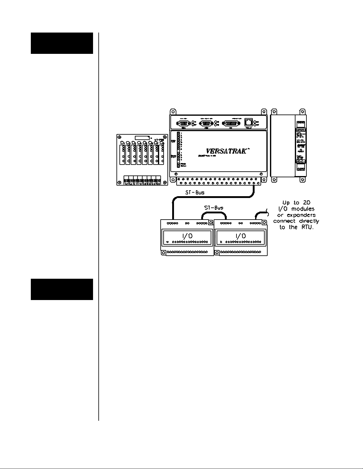
A typical VersaTRAK or Mini-VersaTRAK station consists ofa DC power supply, an RTU
and optional expansion I/O modules. SIXTRAK Expansion I/O modules connect to the
RTU through a daisy-chained "ST-Bus" cable. RemoteTRAK and EtherTRAK I/O modules
connect to the RTU through RS485 and Ethernet, respectively. SIXTRAK modules are
shown in the diagram below.
Typical VersaTRAK and MINI-VersaTRAK Components
Expansion
I/O Modules Eight additional discrete I/O points can be added to any VersaTRAK or Mini-VersaTRAK
RTU by using the VT-PB8 expansion board. This board accepts single point plug-in
modules in any combination. The VT-PB8 connects to the RTU through a supplied 20
conductor ribbon cable.
All VersaTRAK and Mini-VersaTRAK RTUs have a ST-Bus port that can control up to 20
SIXTRAK I/O modules directly. Up to 128 modules can be connected to the ST-Bus port
by using a SIXTRAK I/O expander (part number ST-EX-001-20U) after each 20 modules.
All SIXTRAK I/O modules are supported by VersaTRAK and Mini-VersaTRAK RTUs.
RemoteTRAK I/O modules can be connected directly to the RS485 port ofa VersaTRAK or
Mini-VersaTRAK. If an RS485 port is not available, then an RS232 port and an RS232 to
RS485 converter (SIXNET part number RM-232-485-4U) can be used. All RemoteTRAK
I/O modules are supported by VersaTRAK and Mini-VersaTRAK RTUs.
EtherTRAK I/O modules can be connected through hubs and other off-the-shelf Ethernet
media to the Ethenet port of a VersaTRAK. All EtherTRAK I/O modules are supported by
VersaTRAK RTUs.
VersaTRAK RTU User Manual Page 4 of 31 Last Revised: 05/23/02
SIXNET •
••
•Box 767 •
••
•Clifton Park, NY 12065 USA •
••
•+1 (518) 877-5173 •
••
•FAX +1 (518) 877-8346 •
••
•support@sixnetio.com
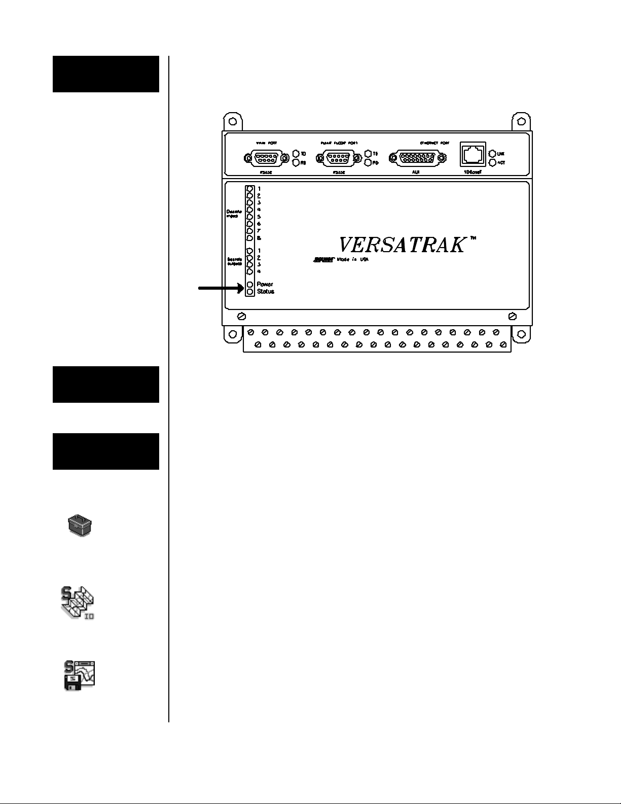
Power, Status
LEDs
Each VersaTRAK or Mini-VersaTRAK RTU has a Power LED, and a status LED that
indicates configuration and communication status by blinking in different ways. The status
LED is documented fully in Section 9.
Isolation
Every on-board discrete I/O channel is isolated from logic circuitry and from any expansion
I/O modules for fault-free operation. Additional levels of isolation are provided with
SIXTRAK I/O modules. Refer to the product specifications in the SIXNET online help files
for more information.
SIXNET
Software Tools SIXNET supplies the "mission oriented" tools you need for every step ofyour project from
the initial specification, through startup, and years of trouble free operation. Configuration
information flows between SIXNET Windows, saving you time (you don't have to enter
data multiple times) and dramatically reducing data entry errors. Refer to the on-line help in
each program for details.
SIXNET
I/O Tool
Kit
The SIXNET I/O Tool Kit is a configuration, calibration and maintenance tool for
VersaTRAK and Mini-VersaTRAK RTUs. Use the SIXNET I/O Tool Kit to specify
VersaTRAK systems, create a bill of materials and price the system. Then configure I/O
features, perform channel-by-channel calibrations in meaningful engineering units, and
perform live diagnostics at each RTU.
IOmap
Control
Room Control Room IOmap is a shared resource database that enables multiple Windows programs
to simultaneously access SIXNET I/O. Built-in scan tasks allow communication over serial
ports, Ethernet and SIXNET networks. The Control Room talks to your applications with a
flexible combination of DDE, Modbus protocol, and direct DLL function calls (from Visual
Basic and C/C++). Access the IOmap functions from within the SIXNET I/O Tool Kit.
Sixlog
Sixlog Sixlog is datalogging software for VersaTRAK and Mini-VersaTRAK RTUs. Data is logged
into protected memory in the RTU. Then Sixlog uploads the data files and saves them into
ASCII format files that are easy to import into databases, spreadsheets and other Windows
applications. Access the Sixlog functions from within the SIXNET I/O Tool Kit.

VersaTRAK RTU User Manual Page 5 of 31 Last Revised: 05/23/02
SIXNET •
••
•Box 767 •
••
•Clifton Park, NY 12065 USA •
••
•+1 (518) 877-5173 •
••
•FAX +1 (518) 877-8346 •
••
•support@sixnetio.com
Getting Started
Following these steps will make installation and start-up easier.
Mount the Hardware
If you purchased a VersaTRAK Packaged System, the complete enclosure is ready for
installation on any flat surface. If you purchased individual VersaTRAK components,
refer to Section 2 for information on installing them into an enclosure.
Install ST-Bus Wiring to the I/O Modules
Make ST-Bus wiring connections between the VersaTRAK or Mini-VersaTRAK and
expansion modules (ifany). Refer to Section 3 for ST-Bus wiring guidelines. Ifyou have
a VersaTRAK Packaged System, this has already been done for you.
Connect Power and I/O Wiring
Connect AC power to the power supply. Make DC power connections from the power
supply to the VersaTRAK or Mini-VersaTRAK RTU and to the I/O modules (as
needed.) Make field wiring connections to the VersaTRAK or Mini-VersaTRAK I/O
channels and any peripheral equipment. Refer to the individual module sections in this
manual for connection details.
Install Communication Cabling
If you did not purchase a factory communication cable (ST-CABLE-PF), fabricate and
install an RS232 cable between your computer and the Plant Floor serial port on the
VersaTRAK or Mini-VersaTRAK RTU. See Section 9. If you have a VersaTRAK
Packaged System, a factory cable (ST-CABLE-PF) has been supplied.
Fabricate and install RS232, RS422 and RS485 cables as needed. See Section 9. Ifyou
are using Ethernet, install the correct cabling and peripherals. Refer to the documentation
for your Ethernet communication devices for details.
Apply Power
Power up the RTU and related peripherals. Observe the status LED on the RTU and
each I/O module. The normal conditions are as follows:
Module Type LED, Normal Indication
VersaTRAK RTU in any enclosure Power and Status LEDs On
SIXTRAK I/O modules in Packaged System Status LEDs On (ready)
SIXTRAK I/O modules in user enclosure Status LEDs Blinking
(setup is needed)
Refer to Section 9 ifa Power or Status LED is not lit as shown above.
Configure Using the SIXNETI/O Tool Kit Program
Refer to the steps on the next page to create a hardware configuration for each RTU. Refer
to the on-line help in the SIXNET I/O Tool Kit program.
Test the Hardware
Use the Test I/O function in the SIXNET I/O Tool Kit program to verify proper I/O
operation in all VersaTRAK or Mini-VersaTRAK stations. Refer to the SIXNET I/O
Tool Kit on-line help.
Configure Your Computer Using IOmap
Begin with the "IOmap" step on the next page to create and test a configuration for your
computer. Refer to the on-line help in IOmap for more information.
If You Have Difficulty
If you experience startup trouble, refer to Section 9 of this manual. The diagnostic
procedures in this section may help point you to the source ofthe problem.

VersaTRAK RTU User Manual Page 6 of 31 Last Revised: 05/23/02
SIXNET •
••
•Box 767 •
••
•Clifton Park, NY 12065 USA •
••
•+1 (518) 877-5173 •
••
•FAX +1 (518) 877-8346 •
••
•support@sixnetio.com
Using SIXNET
Windows
Software
Note: An expanded version of this page has been provided as on-line help. To access it,
click on the Getting Started icon in the SIXNET I/O Tool Kit program.
Run the SIXNET I/O Tool Kit program and create your panel layouts. Then configure
operating parameters for the RTU and I/O modules, including channel tag names. Save this
information to a project file. Link the expansion I/O modules (if any) and load your
configuration to the RTU. Using the Test I/O function, verify that you can read and write your
I/O. Then exit the SIXNET I/O Tool Kit.
Note: Set tag name restrictions in the SIXNET I/O Tool Kit program before creating tag
names to ensure compatibility when exporting them for usage in other Windows
applications.
Your VersaTRAK or Mini-VersaTRAK I/O is now ready to run. If you will be running a
Windows application that requires an I/O driver such as Control Room, then continue with
the following steps.
IOmap
Create a Control Room IOmap from within the SIXNET I/O Tool Kit. You will be presented
with an Autoload option. Ifyou use it "Yes", an IOmap will automatically be created for your
system. When prompted, select/configure the communication devices and protocol servers.
Resave your project file. Then choose the Run command from the Operations menu to load
the map into your computer's memory.
Open the Test I/O window and verify that your I/O is being read and written. Then exit the
Test I/O window.
Your computer is now ready to exchange I/O data with your Windows applications. (Refer to
the "How to Access SIXNET I/O From a Windows Application" topic in the SIXNET I/O
Tool Kit online help.)
Some Windows applications, such as ISaGRAF, Citect and Intellution FIX, can import
SIXNET tag names. If your Windows application supports this feature, run the SIXNET I/O
Tool Kit and open your project file. Export your tag names to a file using the appropriate
format.
Note: Ifyou are exporting tag names for ISaGRAF, Citect or Intellution, you must create, or
already have, a project to export tag data into.
Power
Switch
You can use the Power Switch utility to provide automatic startup of the Control Room
IOmap when you start Windows on your computer. Refer to the Power Switch help topics in
the SIXNET I/O Tool Kit online help.
Sixlog
If you will be logging data in the VersaTRAK RTU, then create the appropriate datalog
configuration(s) and load them into the RTU. Refer to the Sixlog topics in the SIXNET I/O
Tool Kit online help for details.
If you are using the ISaGRAF IEC1131 programming software, refer to the SIXNET -
ISaGRAF on-line help for additional information.

VersaTRAK RTU User Manual Page 7 of 31 Last Revised: 05/23/02
SIXNET •
••
•Box 767 •
••
•Clifton Park, NY 12065 USA •
••
•+1 (518) 877-5173 •
••
•FAX +1 (518) 877-8346 •
••
•support@sixnetio.com
Panel
Assembly A VersaTRAK or Mini-VersaTRAK RTU and power supply mount directly to the subpanel
in your enclosure. SIXNET I/O modules snap onto DIN rail strips fastened to the subpanel.
Recommended DIN rail spacing is 8 inches (20 cm). This spacing allows room for wire duct
to be installed without obstructing field wiring installation.
SIXNET I/O modules are typically installed against one another, but space can be left between
modules to accommodate other DIN rail mounted components such as terminal blocks. End
clamps are recommended to restrict side-to-side movement. Upcoming figures show the
physical dimensions of the VersaTRAK components. Refer to the manuals for SIXNET I/O
modules for their mounting dimensions.
SIXNET I/O and RTU components can be installed in any orientation and order on your
panel. The modules are typically interconnected using ST-Bus wiring, beginning with the
VersaTRAK RTU. Refer to Section 3 for more information on ST-Bus wiring.
Sample Panel Layout
For a 36” x 30”
Enclosure
DIN EN50022 Suppliers
Manufacturer Type
Altech PR30
Entrelec TS35
Phoenix NS35/7.5
Wago TS35
Weco H-35
Weidmuller TS35
Wieland TS35

VersaTRAK RTU User Manual Page 8 of 31 Last Revised: 05/23/02
SIXNET •
••
•Box 767 •
••
•Clifton Park, NY 12065 USA •
••
•+1 (518) 877-5173 •
••
•FAX +1 (518) 877-8346 •
••
•support@sixnetio.com
VersaTRAK, Mini VersaTRAK RTU Dimensions
VT-PS-024-01N Power Supply Dimensions
VT-PB8 I/O Board Dimensions

VersaTRAK RTU User Manual Page 9 of 31 Last Revised: 05/23/02
SIXNET •
••
•Box 767 •
••
•Clifton Park, NY 12065 USA •
••
•+1 (518) 877-5173 •
••
•FAX +1 (518) 877-8346 •
••
•support@sixnetio.com
Power
Requirements VersaTRAK and Mini-VersaTRAK RTUs, SIXTRAK I/O expanders and all SIXNET I/O
modules accept 24 volts DC from a VersaTRAK power supply (VT-PS-024-01N) or from a
user DC power source. (See below.)
A VersaTRAK or Mini-VersaTRAK RTU will power up to 20 SIXTRAK I/O modules
through the ST-Bus port wiring. Any additional (beyond 20) SIXTRAK I/O modules must
receive their power from SIXTRAK I/O expanders (ST-EX-001-20U).
DC power for RemoteTRAK and EtherTRAK I/O modules is provided through direct
connections to each module. Refer to the SIXNET Product Catalog for power consumption
ratings of each module.
AC Power Wiring
and Fusing
The VT-PS-024-01N power supply operates on 90V to 260V sinusoidal AC power at 47 to
63 Hz. If fusing is required, use a 1 amp slow blow fuse for 110 VAC. For 220 VAC use a
0.5 amp slow blow fuse.
DC Power Wiring
(VT-PS-024-01N)
The VersaTRAK or Mini-VersaTRAK RTU, SIXTRAK I/O expanders and user
instrumentation loops can be powered from the VT-PS-024-01N power supply. The VT-PS-
024-01N supplies 24 volts DC at a maximum oftwo amps.
DC Power Wiring
(User DC Source)
The VersaTRAK or Mini-VersaTRAK RTU, I/O expanders and user instrumentation loops
can be powered from a single DC source from 18 to 30 volts. A DC power source of10 to 30
volts can be used ifno SIXTRAK I/O modules are connected to the ST-Bus port.
To calculate the current requirements, add the wattage required for the RTU and SIXNET I/O
modules in use, then divide the total wattage by the DC power source voltage. Then add any
current needed for user instrumentation loops.
VersaTRAK DC Power and ST-Bus Connections

VersaTRAK RTU User Manual Page 10 of 31 Last Revised: 05/23/02
SIXNET •
••
•Box 767 •
••
•Clifton Park, NY 12065 USA •
••
•+1 (518) 877-5173 •
••
•FAX +1 (518) 877-8346 •
••
•support@sixnetio.com
ST-Bus Wiring Connect ST-Bus wiring between SIXTRAK expansion I/O modules and the VersaTRAK
RTU as shown in the diagram below. Refer to the SIXTRAK Installation and Maintenance
user manual for ST-Bus wiring guidelines. Connections for the Mini-VersaTRAK are shown
on page 10.
Screw Terminal
Torque Tighten the screw terminal on the VT-PS-024-01N power supply and optional VT-PB8
discrete I/O board to a maximum of 3.48 in-lbs. Tighten the screw terminals on the
VersaTRAK and Mini-VersaTRAK RTUs to a maximum of7.00 in-lbs.
Mini-VersaTRAK DC Power and ST-Bus Connections

VersaTRAK RTU User Manual Page 11 of 31 Last Revised: 05/23/02
SIXNET •
••
•Box 767 •
••
•Clifton Park, NY 12065 USA •
••
•+1 (518) 877-5173 •
••
•FAX +1 (518) 877-8346 •
••
•support@sixnetio.com
VersaTRAK
Discrete Inputs
The VersaTRAK RTU has eight on-board discrete input channels that accept DC signals
from 10 to 30 volts.
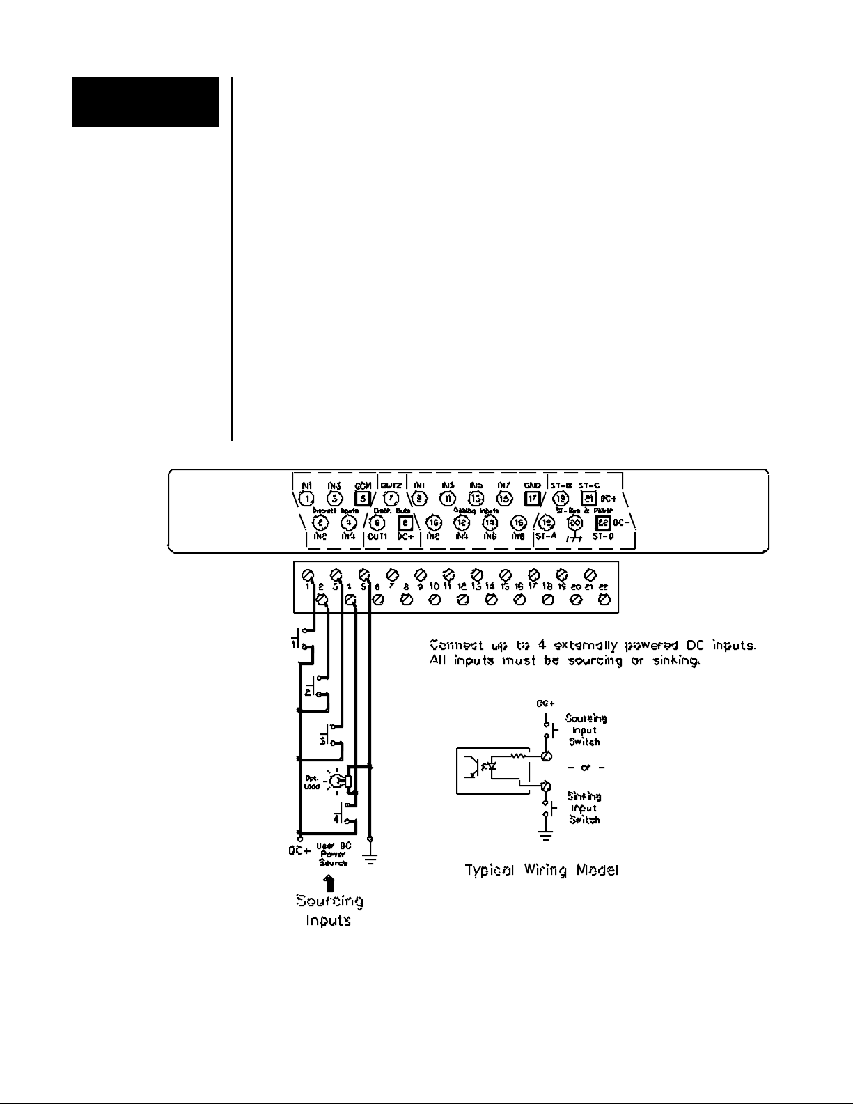
DC Input Wiring
There are two groups of four discrete input channels. Within each group, one wire from each
of the four input signals is connected to a single common terminal. Up to eight signals may
be connected to the VersaTRAK RTU in sourcing or sinking configurations. Refer to the
diagram below for sample wiring connections.
Discrete Input
Group Isolation
The eight discrete inputs are optically isolated (in groups of four) from each other and from
the VersaTRAK circuitry and expansion I/O modules.
Sinking or
Sourcing Wiring
DC inputs are typically wired in a sourcing configuration as shown in the upcoming
diagram. VersaTRAK DC input channels will read either DC sinking or sourcing wiring. To
configure sinking DC wiring, connect the positive power input to the COM terminal for the
group offour channels.
Counter
Feature
All eight discrete input channels have an input count accumulator feature. If this feature is
enabled (in the SIXNET I/O Tool Kit), an analog input register will report a unipolar
(unsigned) 16-bit count value that increments on each OFF to ON transition of the
corresponding input. The maximum count input rate is 100 Hz (6000 pulses/min). These
accumulations initialize at zero each time power is cycled. They cannot be reset under
software control.
VersaTRAK On-board Discrete Input Connections
VersaTRAK RTU User Manual Page 12 of 31 Last Revised: 05/23/02
SIXNET •
••
•Box 767 •
••
•Clifton Park, NY 12065 USA •
••
•+1 (518) 877-5173 •
••
•FAX +1 (518) 877-8346 •
••
•support@sixnetio.com
Mini-VersaTRAK
Discrete Inputs The Mini-VersaTRAK RTU has four on-board discrete input channels that accept DC signals
from 10 to 30 volts
DC Input Wiring
One wire from each of the four input signals is connected to a single common terminal. Up to
four signals may be connected to the Mini-VersaTRAK RTU in sourcing or sinking
configurations. Refer to the diagram below for sample wiring connections.
Discrete Input
Group Isolation
The four discrete inputs are optically isolated (in groups offour) from each other and from the
Mini-VersaTRAK circuitry and expansion I/O modules.
Sinking or
Sourcing Wiring
DC inputs are typically wired in a sourcing configuration as shown in the upcoming
diagram. Mini-VersaTRAK DC input channels will read either DC sinking or sourcing
wiring. To configure sinking DC wiring, connect the positive power input to the COM
terminal for the four channels.
Counter
Feature
All four discrete input channels have an input count accumulator feature. If this feature is
enabled (in the SIXNET I/O Tool Kit), an analog input register will report a unipolar
(unsigned) 16-bit count value that increments on each OFF to ON transition of the
corresponding input. The maximum count input rate is 100 Hz (6000 pulses/min). These
accumulations initialize at zero each time power is cycled. They cannot be reset under
software control.
Mini-VersaTRAK On-board Discrete Input Connections
VersaTRAK RTU User Manual Page 13 of 31 Last Revised: 05/23/02
SIXNET •
••
•Box 767 •
••
•Clifton Park, NY 12065 USA •
••
•+1 (518) 877-5173 •
••
•FAX +1 (518) 877-8346 •
••
•support@sixnetio.com
VersaTRAK
Discrete Outs The VersaTRAK RTU has four on-board discrete output channels that switch power from 0
to 30 volts DC at a maximum of 1 amp per output. VersaTRAK wiring connections and
features are detailed below.
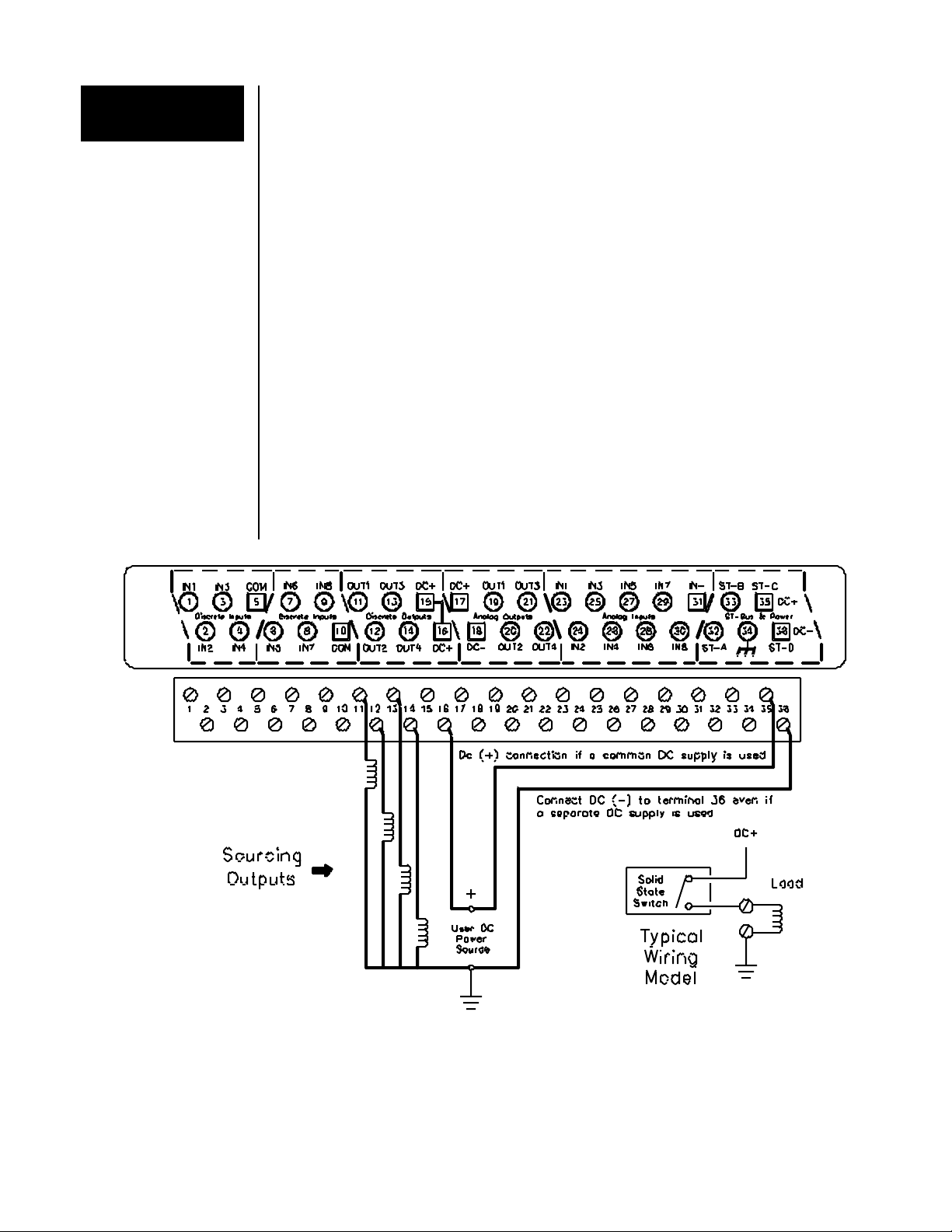
DC Power
Requirements
These discrete outputs switch user supplied DC power. This power source may be separate
from the DC power that runs the VersaTRAK, or the same DC power source may be used. If
a separate DC power source is used, connect the DC (-) of that power source to the DC (-)
terminal 36 on the VersaTRAK RTU.
DC Output Wiring
The user DC power (+) wire is connected to either of the two DC(+) terminals (15 and 16)
on the VersaTRAK RTU. This power will be passed to the OUT terminal ofa given channel
when that output is turned on by your control software. Up to four devices may be connected
to the VersaTRAK RTU in sourcing configurations only. Refer to the diagram below for
sample wiring connections.
VersaTRAK On-board Discrete Output Connections

VersaTRAK RTU User Manual Page 14 of 31 Last Revised: 05/23/02
SIXNET •
••
•Box 767 •
••
•Clifton Park, NY 12065 USA •
••
•+1 (518) 877-5173 •
••
•FAX +1 (518) 877-8346 •
••
•support@sixnetio.com
Mini-VersaTRAK
Discrete Outs The Mini-VersaTRAK RTU has two on-board discrete output channels that switch power
from 10 to 30 volts DC at a maximum of 1 amp per output. Mini-VersaTRAK wiring
connections and features are detailed below.
DC Power
Requirements
These discrete outputs switch user supplied DC power. This power source may be separate
from the DC power that runs the VersaTRAK, or the same DC power source may be used. If
a separate DC power source is used, connect the DC (-) of that power source to the DC (-)
terminal 22 on the Mini-VersaTRAK RTU.
DC Output Wiring
The user DC power (+) wire is connected to the DC(+) terminal 8 on the Mini-VersaTRAK
RTU. This power will be passed to the OUT terminal ofa given channel when that output is
turned on by your control software. Up to two devices may be connected to the Mini-
VersaTRAK RTU in sourcing configurations only. Refer to the diagram below for sample
wiring connections.
Mini-VersaTRAK On-board Discrete Output Connections

VersaTRAK RTU User Manual Page 15 of 31 Last Revised: 05/23/02
SIXNET •
••
•Box 767 •
••
•Clifton Park, NY 12065 USA •
••
•+1 (518) 877-5173 •
••
•FAX +1 (518) 877-8346 •
••
•support@sixnetio.com
Overview
The VT-PB8 is a discrete I/O expansion board for VersaTRAK and Mini-VersaTRAK
RTUs. This board has eight isolated discrete I/O channels and connects to the RTU through
the supplied ribbon cable. Each discrete I/O channel may be configured as an input or an
output by plugging in the appropriate I/O module and defining the channel as an input or
output in the SIXNET I/O Tool Kit configuration.
Discrete
Input Wiring
Up to eight input signals may be connected to the VT-PB8 in sourcing or sinking
configurations. Refer to the diagram below for sample wiring connections.
Discrete
Output Wiring
Up to eight output circuits may be connected to the VT-PB8 in sourcing or sinking
configurations. Refer to the diagram below for sample wiring connections.
Power
Requirements
VT-PB8 discrete outputs switch user supplied power. The AC or DC power source may be
separate from the DC power that runs the VersaTRAK. IfDC outputs are populated, the same
DC power source may be used for the VersaTRAK or Mini-VersaTRAK, and for the VT-
PB8 discrete outputs.
VT-PB8 Discrete I/O Connections
VersaTRAK RTU User Manual Page 16 of 31 Last Revised: 05/23/02
SIXNET •
••
•Box 767 •
••
•Clifton Park, NY 12065 USA •
••
•+1 (518) 877-5173 •
••
•FAX +1 (518) 877-8346 •
••
•support@sixnetio.com
VersaTRAK
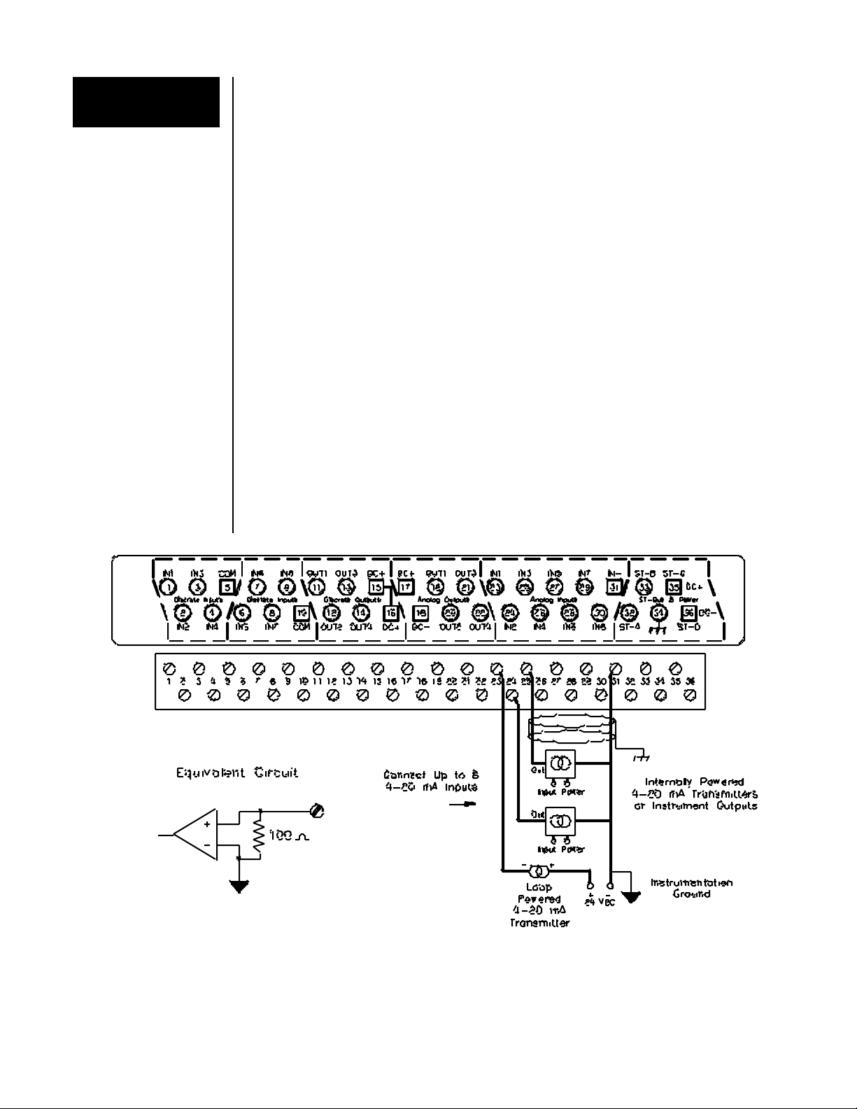
Analog Inputs The VersaTRAK RTU has eight analog input channels that accept loop powered or self
powered 4-20 mA signals.
Analog Input
Wiring
One screw terminal (31) is provided for the return wires from all input channels. One terminal
is provided for each analog input signal. If any of your 4-20 mA transmitters require loop
power, connect 24 VDC into the loop as shown below. (The 24 VDC may come from an
external DC power source or from the VT-PS-024-01N power supply.) Connect all self-
powered 4-20 mA input field devices as shown in the diagram below.
Analog Input
Group Isolation
The eight VersaTRAK analog input channels are isolated (as a group) from the VersaTRAK
circuitry and expansion I/O modules.
Analog Input
Scaling
These 4-20 mA inputs are reported as unscaled values from 0 to 32767. Refer to the SIXNET
I/O Tool Kit online help system for more information.
Open Loop
Detection Feature
The SIXNET I/O Tool Kit configuration program provides a selection that allows inputs
below 4 mA to be reported as zero, or be reported as negative values to detect loop failure.
Replaceable
Current Shunts
VersaTRAK RTUs have a replaceable 100 ohm precision current shunt for each analog input,
should a faulty field device or wiring error causes the original shunt to overheat.
Note: Shunt replacement requires VersaTRAK disassembly. Consult SIXNET for details
should shunt replacement become necessary.
VersaTRAK On-board Analog Input Connections

VersaTRAK RTU User Manual Page 17 of 31 Last Revised: 05/23/02
SIXNET •
••
•Box 767 •
••
•Clifton Park, NY 12065 USA •
••
•+1 (518) 877-5173 •
••
•FAX +1 (518) 877-8346 •
••
•support@sixnetio.com
Mini-VersaTRAK
Analog Inputs
The Mini-VersaTRAK RTU has eight analog input channels that accept loop powered or self
powered 4-20 mA signals.
Analog Input
Wiring
One screw terminal (17) is provided for the return wires from all input channels. One terminal
is provided for each analog input signal. If any of your 4-20 mA transmitters require loop
power, connect 24 VDC into the loop as shown below. (The 24 VDC may come from an
external DC power source or from the VT-PS-024-01N power supply.) Connect all self-
powered 4-20 mA input field devices as shown in the diagram below.
Analog Input
Scaling
These 4-20 mA inputs are reported as unscaled values from 0 to 32767. Refer to the SIXNET
I/O Tool Kit online help system for more information.
Open Loop
Detection Feature
The SIXNET I/O Tool Kit configuration program provides a selection that allows inputs
below 4 mA to be reported as zero, or be reported as negative values to detect loop failure.
Replaceable
Current Shunts
Mini-VersaTRAK RTUs have a replaceable 100 ohm precision current shunt for each analog
input, should a faulty field device or wiring error causes the original shunt to overheat.
Note: Shunt replacement requires Mini-VersaTRAK disassembly. Consult SIXNET for
details should shunt replacement become necessary.
Mini-VersaTRAK On-board Analog Input Connections

VersaTRAK RTU User Manual Page 18 of 31 Last Revised: 05/23/02
SIXNET •
••
•Box 767 •
••
•Clifton Park, NY 12065 USA •
••
•+1 (518) 877-5173 •
••
•FAX +1 (518) 877-8346 •
••
•support@sixnetio.com
Applicable
Part Numbers
This section documents the following VersaTRAK RTU models:
VT-A3-220-24P, 44P, or –54P VT-A3-420-24P, -44P, or –54P
VT-A3-222-24P, -44P, or –54P VT-A3-422-24P, -44P, or –54P
VT-A3-22E-24P, -44P, or –54P VT-A3-42E-24P, -44P, or –54P
VersaTRAK
Analog Outputs
The aforementioned VersaTRAK models have four 4-20 mA analog output signals. These
outputs are powered from a DC power source. The 24 VDC may come from an external DC
power source or from the VT-PS-024-01N power supply.
Analog Output
Wiring
Two screw terminals are provided for the DC power source. One terminal is provided for each
output signal. The DC (-) terminal is used for the return wire of each analog output circuit.
VersaTRAK On-board Analog Output Connections
VersaTRAK RTU User Manual Page 19 of 31 Last Revised: 05/23/02
SIXNET •
••
•Box 767 •
••
•Clifton Park, NY 12065 USA •
••
•+1 (518) 877-5173 •
••
•FAX +1 (518) 877-8346 •
••
•support@sixnetio.com
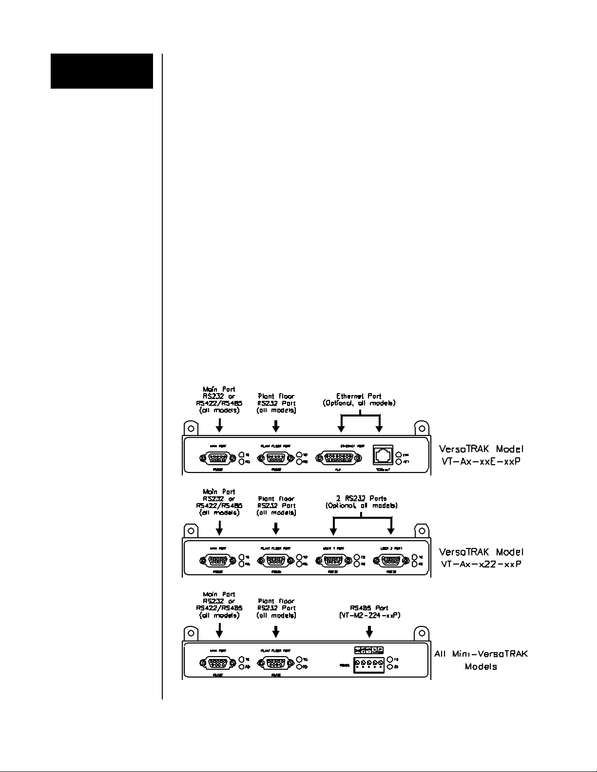
Communication
ports
All VersaTRAK and Mini-VersaTRAK RTUs have two communication ports; a Plant Floor
port and a Main port. Optionally, a VersaTRAK RTU can have two additional RS232 ports
or an Ethernet port. The Mini-VersaTRAK model VT-M2-224-xxP has an additional RS485
port. All VersaTRAK / Mini-VersaTRAK communication ports support SIXNET Universal
protocol (default) and Modbus ASCII / RTU protocols. The baud rate and other
communication parameters for all ports are assigned in the SIXNET I/O Tool Kit. (Refer to
the SIXNET I/O Tool Kit online help for information on setting communication parameters.)
Plant Floor Port
(All Models)
The Plant Floor RS232 port provides a connection to any RS232 device, typically a
computer. Plant Floor serial port wiring is shown on page 20.
Main Port
(All Models)
The Main port is an RS232 or RS422/RS485 port, depending on the VersaTRAK or Mini-
VersaTRAK model. The main port may be connected to any RS232 or RS422/RS485
device, or in some cases, may be connected to other RTUs in a passthru configuration. (See
below.) Wiring examples for each type of main port are shown on upcoming pages.
RS485 Port
(VT-M2-224-xxP) This RS485 port can be used for two-wire communication to RS485 devices such as
RemoteTRAK I/O modules. SIXNET and Modbus protocols are supported.
VersaTRAK Optional
Communication
Ports
The two optional RS232 User serial ports can be used for communication to RS232 devices.
The optional Ethernet port is accessible through the supplied 10BaseT or AUI connectors,
but not both. The VersaTRAK RTU will automatically monitor both connectors for network
traffic. Once activity is located on a connector, the VersaTRAK RTU will only monitor that
connector for messages until power is cycled.
All standard Ethernet devices and communications media are supported.
VersaTRAK / Mini-VersaTRAK Communication Ports
VersaTRAK RTU User Manual Page 20 of 31 Last Revised: 05/23/02
SIXNET •
••
•Box 767 •
••
•Clifton Park, NY 12065 USA •
••
•+1 (518) 877-5173 •
••
•FAX +1 (518) 877-8346 •
••
•support@sixnetio.com
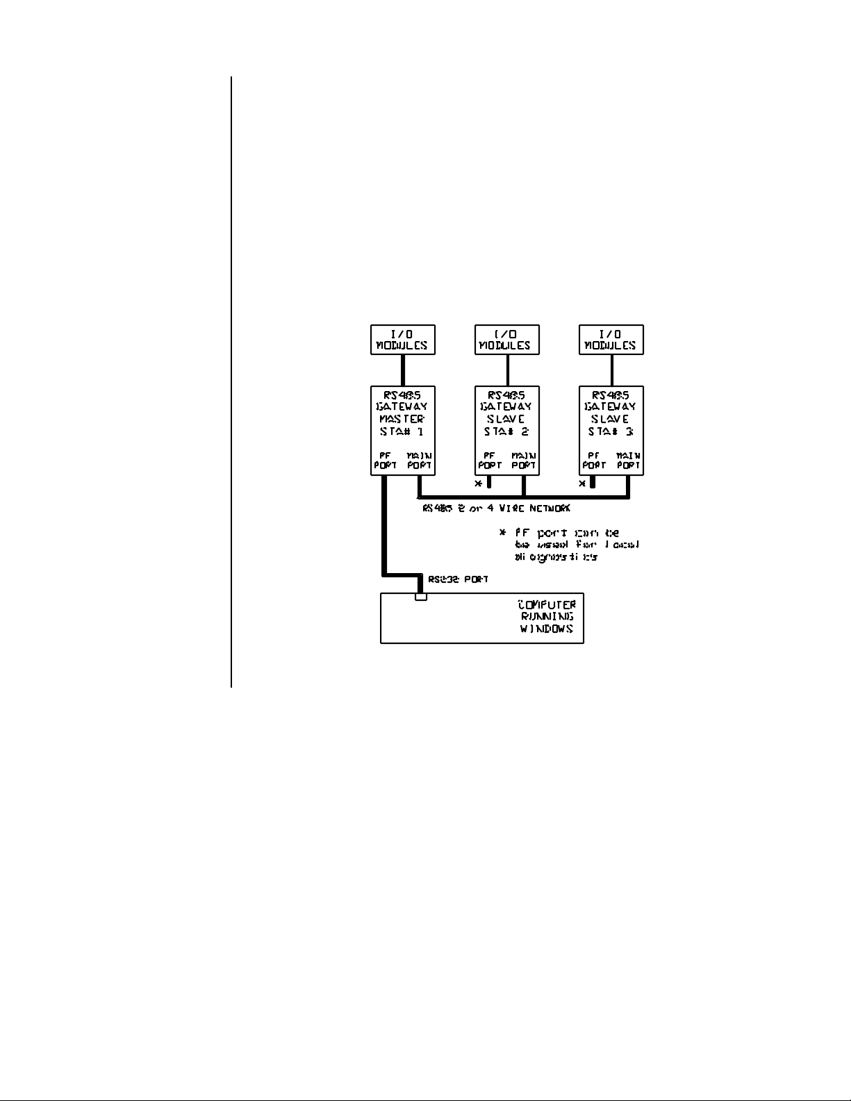
Passthru Mode
Overview Passthru mode is a communication choice for VersaTRAK and Mini-VersaTRAK RTUs.
This selectable mode lets an RTU function as a RS232, RS422/485 or Ethernet converter or
radio modem master, thus eliminating the need for a special communication board in your
computer. For example, you can use passthru mode to communicate to Ethernet or RS422 /
RS485 gateways from a single serial port on your computer.
In the SIXNET I/O Tool Kit configuration, when you enable a passthru connection, the
RTU will bidirectionally pass messages between the two specified ports (RS232,
RS422/RS485 or Ethernet). Up to two passthru connections may exist on a VersaTRAK
RTU.
Connections to passthru stations are documented in the upcoming pages. Please note that
passthru mode requires version 2.08 or newer gateway/RTU firmware to function properly.
Typical RS485 Passthru Connections
This manual suits for next models
1
Table of contents


