SJE Rhombus VARIOspeed Micro User manual

VARIOspeed Micro®
User Manual
22650 County Highway 6
n
PO Box 1708
n
Detroit Lakes, MN 56502
Phone 218-847-1317
n
Fax: 218-847-4617
www.sjerhombus.com
WARNINGS
Failure to read and understand the information provided in this manual may result in personal injury or
death, damage to the product or product failure. Please read each section in its entirety and be sure
you understand the information provided in the section and related sections before attempting any of
the procedures or operations given.
Failure to follow these precautions could result in serious injury or death. Keep these
instructions with warranty after installation. This product must be installed in accor-
dance with National Electrical Code, ANSI/NFPA 70 so as to prevent moisture from
entering or accumulating within the controller housing.
See additional specifications on page 6 of this manual.
ELECTRICAL SHOCK HAZARD
Disconnect power to the VARIOspeed®MICRO VFD drive and wait 10
minutes before removing the terminal cover.
A qualified service person must install and service this product according
to applicable codes and electrical schematics.
EXPLOSION OR FIRE HAZARD
Do not use this product with flammable liquids. Do not install in
hazardous locations as defined by National Electrical Code,
ANSI/NFPA 70.
• Lethal voltages are still present inside the VARIOspeed®MICRO VFD drive after power
is disconnected. Wait 10 minutes to allow internal capacitors to fully discharge before
attempting to connect or disconnect wire or to service this equipment.
• Do not connect incoming power to motor terminals U, V, W. doing so will result in
irreversible damage to the drive.
• Do not connect power to this equipment if it has been damaged or has any missing parts.
• Do not apply power to the VARIOspeed®MICRO VFD drive with the terminal cover
removed.
• Verify that the incoming voltage supply is 230 VAC before applying power to the unit.
• The VARIOspeed®MICRO VFD drive contains no serviceable parts, do not attempt to repair
this equipment.
• The VARIOspeed®MICRO VFD drive must be grounded at the grounding terminal according
to N.E.C. Refer to the electrical connection on page 12.
• The VARIOspeed®MICRO VFD drive has been designed for indoor mounting only. Use the
optional NEMA 3R model for outdoor installations.
• Do not install in ares with: excessive or conductive dust, corrosive or flammable gas,
moisture or rain, excessive heat, regular impact shocks or excessive vibration.
• Do into install in areas where ambient temperature exceeds 40ºC (104ºF).
• HOT! Heat sink temperature may rise to 90ºC (194ºF). Do NOT touch heat sink.

Table of Contents
Introduction .................................................................................................2
Receiving and Preliminary Inspection ........................................................3
Specifications..............................................................................................4
System Setup Diagram for Deep Well Submersible .................................5
System Setup Diagram for Pressure Booster ............................................6
Pressure Tank/Pressure Relief Valve/Low Pressure..................................7
Outline Dimensions.....................................................................................8
Removing the cover to access the terminal blocks....................................8
Mounting .....................................................................................................9
Terminal Wiring Description......................................................................10
Grounding Method....................................................................................11
Filter Options ............................................................................................11
Display and Function Keys Overview.......................................................12
Display Description ...................................................................................12
Function Keys Operation ..........................................................................13
Changing the Set Pressure ......................................................................14
Changing Parameters...............................................................................14
Parameter List ..........................................................................................15
Detailed Parameter Functions ..................................................................16
Fault and Alarm Display & Solutions........................................................18
Causes of Malfunction/Troubleshooting ...................................................18
Warranty Information ................................................................................19
SJE-Rhombus®VARIOspeed®Micro Controller User Manual 1

Introduction
Congratulations, and thank you for your purchase of a VARIOspeed®MICRO series VFD. These
drives are indoor wall-mountable units designed for controlling water pumps in either deep well
applications, or pressure boosting centrifugal pump applications.
Product range
The VARIOspeed®MICRO D & D PLUS in either the 1hp or 2hp size are designed for deep well
submersible pumps and centrifugal pressure booster pumps using 230V single phase incoming
power, and are capable of controlling either single phase or three phase pumps by setting the
appropriate parameters.
Product Features
All VARIOspeed®MICRO series drives have a built-in PID function (non-adjustable) that varies
the speed (Hz) of the pump and provide optimal control for maintaining a constant pressure in a
variety of pumping applications. The information included in this manual will help you maximize the
performance of your VARIOspeed®MICRO VFD, and ensure safe operation of your pump system.
Please keep this manual for future reference.
2SJE-Rhombus®VARIOspeed®Micro Controller User Manual

Receiving and Preliminary Inspection
Included in the box:
1. The VARIOspeed®MICRO VFD
2. Pressure transducer (0-145 PSI range – ¼” NPTM) with 20 ft. of cable
3. Transducer cable
4. Strain reliefs (1 x 0.5”, 2 x 0.75”)
5. User manual
6. Wall mounting bracket (4 screws included)
7. Quick start manual
Verify that all components are included and the VARIOspeed®MICRO VFD model number is
correct.
WARNING: Do not connect power to this equipment if it’s been damaged or has any missing parts.
SJE-Rhombus®VARIOspeed®Micro Controller User Manual 3

4SJE-Rhombus®VARIOspeed®Micro Controller User Manual
Specifications
VARIOspeed®MICRO D (1HP) MICRO D PLUS (2HP)
Input rating
Voltage (V) 1Φ, 200V - 240V, 50/60 Hz
Power (W) 4,300W 5,400W
Current (A) Max. 19.5A Max. 24.5A
Minimum Size
Circuit Breaker 30A (2 Pole) 30A (2 Pole)
Output rating
*Voltage (V) 1Φ, 220V 3Φ, 220V 1Φ, 220V 3Φ, 220V
Power (kW/HP) 0.75kW
(1 HP)
1.5 kW
(2HP)
1.5 kW
(2HP)
2.2 kW
(3HP)
Max. Rated Current (A) Max. 11A Max. 14A
Max. Pump FLA 0-9A 0-12A
Frequency (Hz) 20~80Hz 20~60Hz
Operation
Pressure Range 1-69 PSI
Control Method PID control (Proportional + Integral + Derivative)
Environment
IP Rating IEC-529 IP31
Pollution Degree Pollution Degree 2
Operating Temperature 0ºC ~ +50ºC
Storage Temperature -10ºC ~ +60ºC
Ambient Humidity Less than 95%, Non-condensing
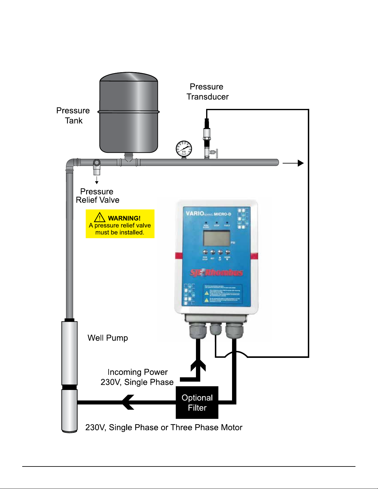
System Setup Diagram for Deep Well Submersible
SJE-Rhombus®VARIOspeed®Micro Controller User Manual 5

System Setup Diagram for Pressure Booster
6SJE-Rhombus®VARIOspeed®Micro Controller User Manual

Pressure Tank/Pressure Relief Valve/Low Pressure
To maintain constant pressure and prevent frequent startup, a small-capacity pressure tank is need-
ed in the system (refer to the minimum capacity of pressure tank table below). The VARIOspeed®
MICRO VFD may use a pressure tank of a larger capacity than listed on the table blow.
Minimum Capacity of Pressure Tank
Flow Rate (GPM) Tank Size
(Total Capacity)
Less than 12.0 4 Gallons
More than 12.0 8 Gallons
Pre-Charge Pressure
1. Initial charge pressure should be at least 70% of the system pressure (Set pressure).
2. To maintain the optimum pressure level, check the air pressure in the tank regularly.
Set Pressure (PSI) Initial Charging
Pressure (PSI)
50 (default) 35
55 39
60 42
65 46
A Pressure Relief Valve Must be Installed.
A pressure relief valve MUST be installed as close as possible to the pump discharge and plumbed
to a drain able to handle the full flow of the pump in the event of a malfunction.
WARNING!
Failure to use a pressure relief valve could result in burst pipes and flooding if a system failure should occur.
Low Pressure Switch Shutdown (optional)
A pressure switch may be used to shut down the pump on low pressure. This switch will open on low
pressure and stop the pump from operating with insufficient water supply. (See pg 12 for electrical
connections.)
SJE-Rhombus®VARIOspeed®Micro Controller User Manual 7

Outline Dimensions
Removing the cover to access terminal blocks
8SJE-Rhombus®VARIOspeed®Micro Controller User Manual
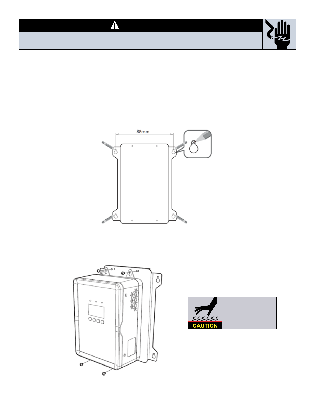
WARNING!
Risk of electrical shock. Wait 10 minutes after disconnecting
the incoming power before removing the cover.
Mounting
The VARIOspeed®MICRO VFD is designed for wall mounting in a clean, cool, and dry location.
First, mount the supplied wall support bracket to the wall. Mark the hole locations and secure with
screws rated for the wall material. The use of the wall support bracket is required to allow air flow
through cooking fins. Do NOT mount outdoors or expose to water, high humidity, corrosive or explo-
sive gasses. Must be mounted vertically and requires a minimum of 100mm (4”) clearance on all
sides for adequate ventilation.
Mount the VARIOspeed®MICRO VFD on the support plate using supplied screws.
HOT!
Heat sink temperature may
rise to 90ºC (194ºF).
Do NOT touch heat sink.
SJE-Rhombus®VARIOspeed®Micro Controller User Manual 9
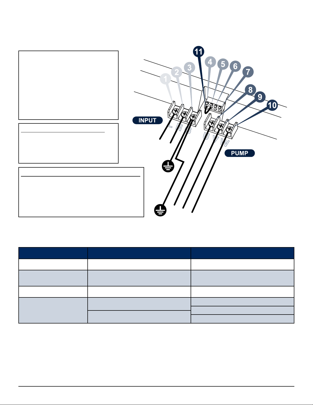
Terminal Wiring Description
1 - (L) Incoming Voltage (L or L1)
2 - (N) Incoming Voltage (N or L2)
3 - (G) Ground Connection
4 - Low Pressure Switch
5 - Low Pressure Switch
6 - Transducer +
7 - Transducer signal
Connect wiring per local code requirements using chart below.
Three Phase motor connection
8 - (U)
9 - (V)
10 - (W)
Single Phase submersible pump connection
8 - (U) start winding - Red (R)
9 - (V) motor winding - Yellow (Y)
10 - (W) motor winding - Black (B)
11 - Factory Jumper
Incoming voltage must be 200V-240 VAC, 50/60 Hz, Single Phase
A 2 pole circuit breaker must be used to protect the VFD. see the table below for correct sizing:
VARIOspeed®MICRO D (1HP) MICRO D PLUS (2 HP)
Input Current Max. 19.5A Max. 24.5A
Minimum Size
Circuit Breaker 30A 30A
Minimum Wire Size 10 AWG 10 AWG
*Motor Cable Size &
Maximum Cable Length
1Φ 14 AWG, 200 ft. 1Φ 14 AWG, 200 ft.
1Φ 14 AWG, 250 ft.
3Φ 14 AWG, 300 ft. 3Φ 14 AWG, 400 ft.
If a pressure switch or level switch is not used, a jumper must be placed between terminal 4 & 5.
If a pressure switch or level switch is used, it must be selected and connected as to open on a fault
condition (low pressure or low water).
10 SJE-Rhombus®VARIOspeed®Micro Controller User Manual
*A filter is recommended for cable lengths over 125ft. See Filter Options on page 11.

Grounding Method
Filter Options
Output noise filters.
These devices are available for 3-phase output applications only.
They are not suitable for single phase pump applications.
These filters can reduce the electrical noise generated by the Variable Frequency Drive.
Variospeed®Micro D (3-phase motor only: Model RLW-001413)
Variospeed®Micro D Plus (3-phase motor only: Model RLW-002113)
SJE-Rhombus®VARIOspeed®Micro Controller User Manual 11

Display Description
Function Keys Operation
Start or stop auto run operation.
(Warning! This will start the pump.)
Escape out of the current parameter.
Accept the changed set pressure by holding for 3 seconds.
Accept the changed value in parameters.
Navigate through parameters and menu.
Change parameter values.
12 SJE-Rhombus®VARIOspeed®Micro Controller User Manual
Viewing Motor Current (A), Frequency (Hz)
and other parameters during automatic operation.
PSI (Pressure Reading)
Hz (Output Frequency)
A (Motor Current)
C (VFD heat sink temperature)
V (Voltage X 100)
V (Voltage)
PSI (Pressure Reading)
Press
Press
Press
Press
Press
Press
Enter manual operation mode
In case of transmitter open or shorted; press DOWN for 3 seconds to go into manual operation mode.
SJE-Rhombus®VARIOspeed®Micro Controller User Manual 13

Changing the Set Pressure
Operation screen – Press SET button for 3 seconds until the word ‘Data’ appears. Now, the set
pressure can be changed. Refer to parameter table on page 15 for values.
Press UP or DOWN button to change the set pressure
Press SET button again for 3 seconds to accept the new set pressure. The display blinks twice, and
then the data disappears.
Caution:
1. Ensure the set pressure is always set above the “deadhead” pint of the pump. If not, the
pumps may keep running even though the user does not use water. It can cause damage
to the pump.
2. Set pressure shall be lower than the high-pressure alarm and higher than the low-pressure
alarm.
3. Changing pump overload protection value may result in damage if set incorrectly.
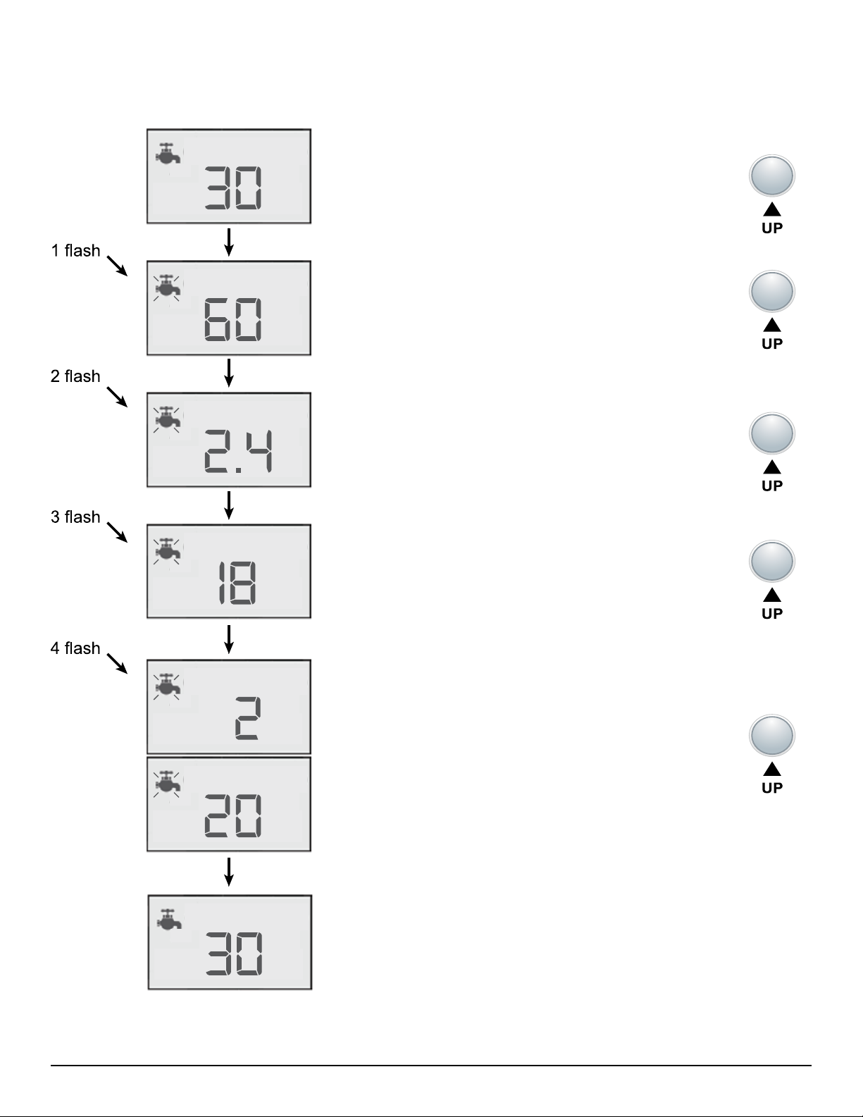
Changing Parameters
Press both the UP / DOWN buttons for 3 seconds until ‘BR-01’ appears. Now the parameter
can be changed.
Press the UP / DOWN button to move to the BR parameter wanted.
Press the SET button, and the word ‘data’ will appear. Now the data of the parameter can be
changed.
Press the UP / DOWN button to change the data.
Press the SET button to accept the new value. The data value will blink twice then the BR
parameter list mode is displayed.
Press the RUN / STOP button to exit the BR parameter mode. The system will operate under
the set value.
Caution:
Certain parameters cannot be changed when in auto run mode. Press the run / stop button to stop
the VFD before entering the parameter change mode to change these parameters.
14 SJE-Rhombus®VARIOspeed®Micro Controller User Manual

SJE-Rhombus®VARIOspeed®Micro Controller User Manual 15
Parameter List
No. Content of parameter Min.
Value
Max.
Value
Default
Value
Unit Remarks Change
during
operation
Set
Press Operating Pressure 11 69 50 PSI Target operating pressure O
BR-01 Base frequency 50 60 60 Hz X
BR-02 Max. Output
Frequency 35 80 60 Hz X
BR-03 Min. Output
Frequency 20 50 30 Hz O
BR-04 Rotating direction 0 1 0 Hz 0: Forward
1: Reverse X
BR-05 Overload Auto Reset 0 99 1 Min. 0: Manual Reset
1-99: Auto Reset Time
BR-06 Transducer Offset -5 5 0 PSI O
BR-07 Restart after sleep
pressure difference 1 15 5 PSI O
BR-08 High pressure alarm 51 99 70 PSI O
BR-09 Low pressure alarm 0 15 10 PSI O
BR-10 Frost Protection 0 99 0 Min. 0: unused
1-99: Time used O
BR-11 Lock parameters 0 2 0
0: Changeable
1: Change N/A
2: Factory Default
X
BR-12 Firmware Revision X
BR-13 Alarm Information Able to record total 10 data X
BR-14 Single or three phase
otor 131 1: 1 Phase
3: 3 Phase X
BR-15 Sleep stop delay time 5 3.0 10 Sec.
Min. X
BR-16 Low pressure restart time 0 30 0 Min. X
BR-17 Pump FLA - MICRO D 0.0 9.0 7.2 Amps Set to match motor max.
amperage X
Pump FLA - MICRO D Plus 12.0 9.6
Caution:
Setting BR-14 & BR-17 incorrectly may result in permanent motor or VFD damage.

Detailed Parameter Functions
BR-01 Base frequency
Base frequency is the frequency that the rated voltage of the inverter can output. Set according to
the rated frequency of the motor.
BR-02 Max. output frequency
Max. output frequency is the max. frequency that the inverter can operate. This value must not
exceed the frequency allowed by the motor.
BR-03 Min. output frequency
When the set pressure is reached and the demand for water stops, the pump will slow down to the
min. output frequency for a certain time and then will go to “sleep”. When this frequency is too high,
frequent ON/OFF cycling will occur. If this frequency is too low, the pump will not shut off and will
cause damage to the pump. During installation, please ensure the sleep function operates correctly
by opening and closing the valves several times and observing correct operation prior to leaving the
site. The default value is recommended for this setup.
BR-04 Rotating direction
When the wire connection of the motor is incorrect, the pump rotation is reversed. Reverse rotation
may cause lower pressure, stop water pumping and noise and vibration. If this occurs change the
setup for the rotating direction in lieu of changing the wire connection.
0: Forward rotation
1: Reverse rotation
BR-05 Auto Reset Time (OL)
0: Manual Reset
1-5: Auto Reset Time (mins.)
BR-06 Transducer offset
In case of a pressure deviation occurring in the system, or the pressure of the gauge is different from
the pressure displayed on the screen, this parameter can offset for this difference.
Before changing this parameter, ensure the pressure gauge is accurate.
BR-07 Restart after sleep pressure differential
After entering “sleep” mode the system will allow the pressure to drop this amount before starting the
pump. If this value is set too small, the pump may operate with frequent Start/Stop cycles. On the
other hand, if this value is set too high, the large pressure drop may be an inconvenient to the user.
BR-08 High pressure alarm
If the current pressure is higher than the high-pressure alarm, the high pressure alarm icon is shown
on screen and the pump stops immediately. If the current pressure drops lower than the high-
pressure alarm, the icon disappears and the pump operates normally again.
BR-09 Low pressure alarm
Note: On initial start up, the low pressure fault will not be activated for 3 minutes to allow for the
piping system to fill.
If the pressure drops for more than 15 seconds below this point, the low pressure alarm is set. The
pump stops and the low pressure alarm icon will appear on the screen. After 15 seconds, the system
automatically restarts, If the pressure returns to normal operating range within 15 seconds, the sys-
tem will continue running. If not, the system will repeat this cycle. If the low pressure alarm remains
after the second time, the pump will stop for the time entered in BR-16 and then attempt to restart.
If the low pressure fault remains, the system will shut down and not restart. The system will need to
be reset by cycling the power and removing the source of the problem.
16 SJE-Rhombus®VARIOspeed®Micro Controller User Manual

BR-10 Frost Protection
Frost protection protects the pump against the cold weather during winter. When the set time is
elapsed, the pump operates under the maximum frequency for 5 seconds, and then stops.
BR-11 Lock parameters
This function locks and initializes the program.
0: Change of parameters is allowed
1: Change of parameters is not allowed
2: Initializes the parameters to factory default values.
BR-12 Firmware version
This displays the firmware version of the program. To improve the performance of the inverter or
solve technical problems, the version is subject to change without prior notice.
BR-13 Alarm information
This parameter captures the history of the 10 most recent alarms. Check the alarm information by
using the UP / DOWN buttons.
BR-14 Setting 1 or 3 phase of the motor
Check the ‘Phase’ on the motor nameplate and set phase as follows;
1: 1 phase
3: 3 phase
Caution:
Applies only to VARIOspeed MICRO D. Setting BR-14 incorrectly may result in permanent motor or
VFD damage
BR-15 Sleep stop delay time
When the drive slows to the minimum output frequency, it delays this amount of time before going to
“sleep”.
BR-16 Low pressure re-start time
After the low pressure alarm, the drive waits this amount of time, then restarts operation. The low
pressure icon starts blinking after the low pressure alarm faults 3 times.
BR-17 Motor FLA
This parameter is to be set to the maximum amperage allowed for the pump motor. If service factor
is needed, this must also be included. The VFD will fault and display drive error if this value is
exceeded for a long period of time.
Caution:
Setting BR-14 & BR-17 incorrectly may result in permanent motor or VFD damage.
SJE-Rhombus®VARIOspeed®Micro Controller User Manual 17
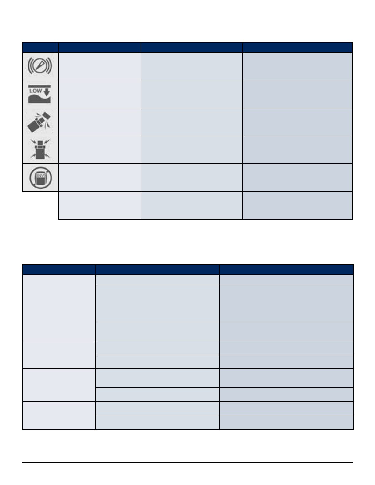
Fault and Alarm Display & Solutions
SYMBOL ALARM STATUS SOLUTION
High pressure warning Exceeding the set pressure Check the system.
Low pressure level
warning Low pressure / water level Check the connection part of
the transmitter.
Transducer open Transmitter disconnect Check the connection of the
transmitter.
Transmitter short Transmitter short-circuit Transmitter is not operating nor-
mally. Replace the sensor.
Drive error Inverter error
Inverter is faulty. Disconnect the
supply power and contact the
distributor.
Over-temperature Heat sink temperature over
90°C (194°F) Ensure proper ventilation.
Causes of Malfunction/Troubleshooting
FAULTS CAUSE ACTIONS
Motor does not run
Motor Fault Repair or replace the motor.
Low input voltage
If the input voltage is lower than the
rated by measurement, please contact
your electric power supply company to
change it to the rated voltage.
Transducer fault Conrm the cable connection
correction of transducer.
Lack of pump ow or
pressure
Inltration of air into the suction pipe
Solid material locked up the pump
Pump noise /
vibration
Mounting bracket loose or broken Tighten or replace the bolts, nuts, and
pipe supports
Reverse rotation direction Check the rotation direction again.
Pump doesn’t stop Min. frequency set too high Adjust parameter
Wrong pump selection Replace it with correct pump
18 SJE-Rhombus®VARIOspeed®Micro Controller User Manual
Table of contents
Other SJE Rhombus Test Equipment manuals


