Skandia Elevator SEH 50/18 User manual

ASSEMBLY INSTRUCTIONS
H-LINE
New generation SEH
50/18, 50/23 & 63/30
ZMA015GB 2020-09-01


SKANDIA ELEVATOR – SEH 50/18, 50/23 & 63/30
Delivery information
Goods inspection
Check that the number of packages agrees with the delivery note and that
the packing and goods are not damaged. Make a note of any damage and
missing materials on the consignment note and report it to the carrier and
to us. Make sure the delivery is complete after unpacking the goods. Any
materials that are found to be incorrect must not be assembled.
Warranty
A 2-year factory warranty from the day of delivery applies to all models
of Skandia Elevator AB machinery. A condition of the warranty and any
subsequent compensation is that Skandia Elevator AB is contacted and an
agreement reached between the customer and Skandia Elevator AB on how
any faults should be rectied. The warranty covers all parts that are damaged
or break due to faulty design or manufacture. Faults and damage caused by
faulty assembly, incorrect use or lack of maintenance will not be covered by
the warranty.
CE mark
A CE mark is located on the transmission side of the elevator head and
is proof that the machine has been manufactured in accordance with EU
machine directives and complies with safety requirements. The CE mark
contains information concerning year of manufacture, model designation and
order number. Always specify the order number in the event of a claim and on
orders for spare parts.
EC Declaration
Skandia Elevator AB
Arentorp
S-53494 Vara
SWEDEN
declare under our sole responsibility that the product:
SEH
order number:
.............................................................................................................................................................................
to which this declaration relates is in conformity with Council Directive of
29 December 2009 on the harmonisation of the member States relating to
machinery, 2006/42/EC.
Unless otherwise specied on the CE mark, the product is manufactured in
accordance with the EU Machinery Directive and is classied as Category II
3D/0D. It is intended for the transport of materials that comply with ATEX
Zone 22 and where the external environment is unclassied.
Vara 1 September 2020
Joakim Larsson, CEO


SKANDIA ELEVATOR – SEH 50/18, 50/23 & 63/30
Contents
Thank you for choosing Skandia Elevator!
Your conveyor system must be assembled correctly and maintained
thoroughly if it is to operate satisfactorily. These assembly instructions and
the separate maintenance instructions must be followed for the warranty to
apply.
We hope you will be pleased with your Skandia conveyor equipment for a long
time.
Machine overview..................................................................................................................6
Safety information...................................................................................................................7
General safety information...............................................................................................................................7
Electrical safety .............................................................................................................................................................8
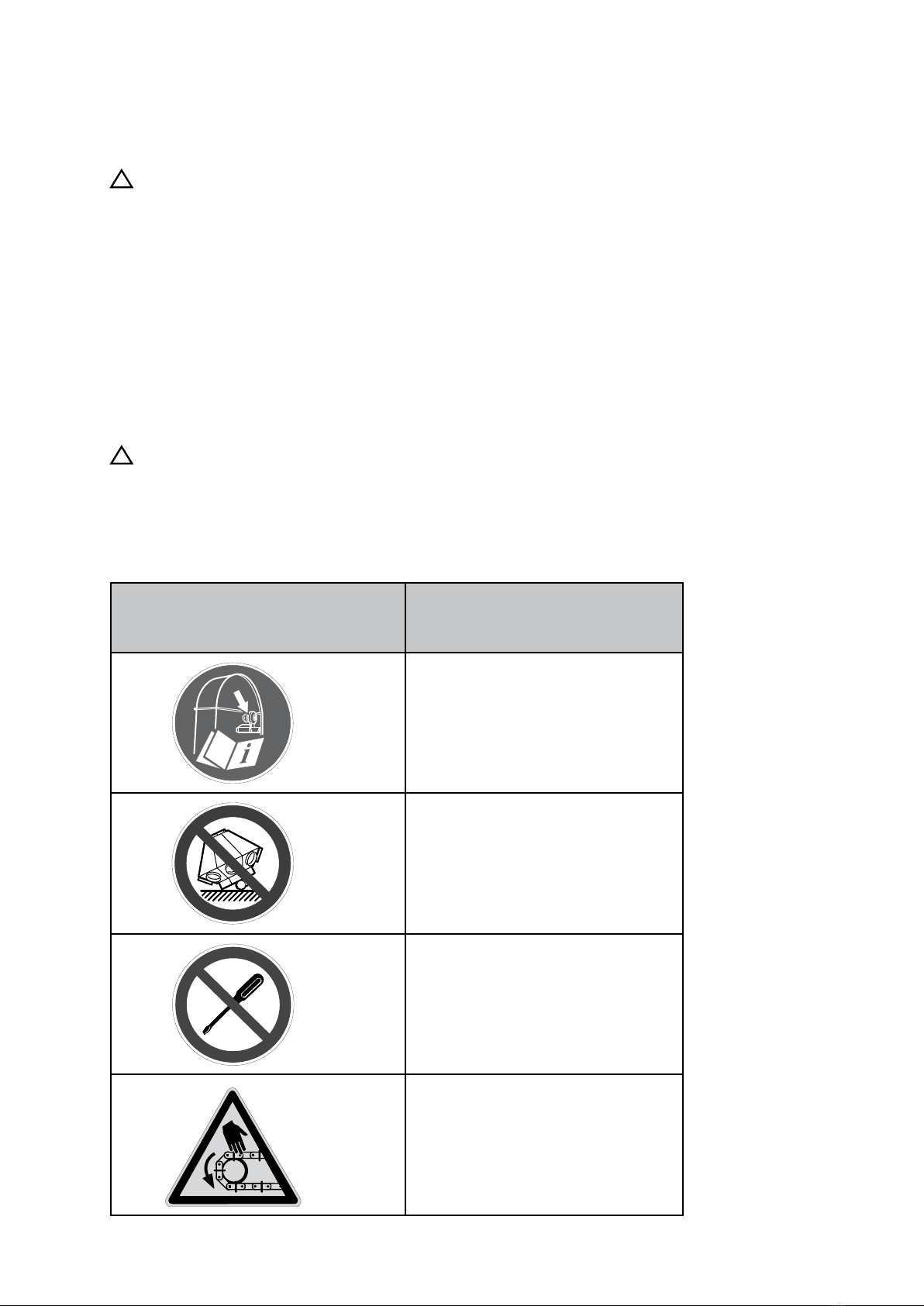
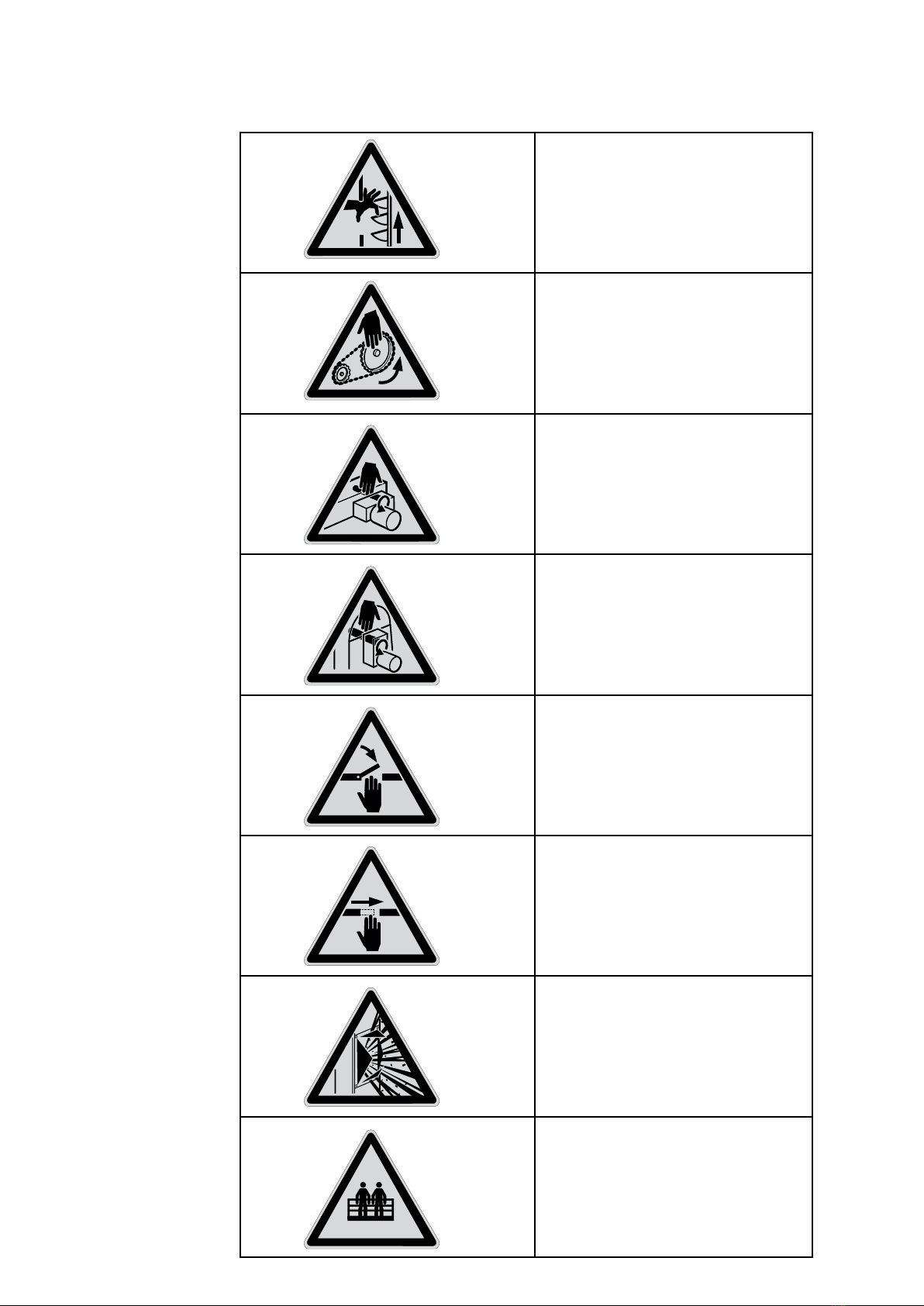
Safety decals....................................................................................................................................................................9
Before assembly.................................................................................................................... 11
Connection of the machine.................................................................................... 13
Location of inlet.........................................................................................................................................................13
Connecting another machine to the elevator...........................................................................14
Connecting the elevator to the conveyor....................................................................................... 14
Assembling the machine............................................................................................ 15
Belt alignment switch.........................................................................................................................................15
Elevator legs.................................................................................................................................................................. 16
Explosion relief panels....................................................................................................................................... 17
Elevator head...............................................................................................................................................................18
Back stop..........................................................................................................................................................................19
Bucket belt......................................................................................................................................................................20
Buckets...............................................................................................................................................................................22
Centring of bucket belt......................................................................................................................................23
Adjusting the splash guard........................................................................................................................... 24
Elevator hood...............................................................................................................................................................25
Speed monitor ............................................................................................................................................................26
Inlet......................................................................................................................................................................................... 27
Water seal........................................................................................................................................................................ 27

6SKANDIA ELEVATOR – SEH 50/18, 50/23 & 63/30
Machine overview
Parts Pos.
Elevator boot 1
Clean out hatch 2
Inlet opening 3
Cover plate, inlet hopper 4
Bucket belt 5
Elevator leg 6
Service door 7
Parts Pos.
Leg spacer plate 8
Back stop with guard 9
Elevator head 10
Elevator hood 11
Geared motor 12
Outlet 13
Inspection cover 14
1
2
2
3
4
5
6
7
8
9
10
12
13
14 11

The owner of the transport equipment is responsible for these assembly
instructions always being available to the tters, electricians, maintenance
technicians and engineering technicians concerned.
Incorrect assembly and/or operation may lead to personal injury or damage
to the conveyor equipment and/or other equipment. It can also cause
malfunctions or a reduction in capacity.
Read the assembly instructions carefully before assembly, electrical
connection, maintenance or operation commences. If any part of these
instructions should be difcult to comprehend, please get in touch with your
reseller for assistance.
The safety information is presented and interpreted as follows:
!
WARNING!
Disregarding instructions given in warnings can cause serious personal
injury or death.
!
IMPORTANT!
Ignoring the instructions given in important texts may cause damage
to the conveyor equipment and/or other equipment. It can also cause
malfunctions or a reduction in capacity.
NB! indicates that the text contains information that will simplify the
assembly process.
General
!
WARNING!
• Ensure that everyone responsible for assembly, electrical connection,
maintenance and operation of the conveyor equipment has read and
understood the instructions and safety information.
• Use protective gloves, helmet, steel-toed boots, ear defenders,
protective goggles and high-vis vest when carrying out assembly,
electrical connection, maintenance and operation of conveyor
equipment.
7
SKANDIA ELEVATOR – SEH 50/18, 50/23 & 63/30
Safety information

!
WARNING!
• Stop the machinery and turn off electric power before attempting any
type of assembly, electrical connection or maintenance work.
• Do not start the machinery without the elevator hood and all hatches,
covers, lids and guards fitted in such a way they can only be opened
with tools.
• Connections to, from and between machinery must be permanently
mounted and fully enclosed. If the design of the installation does not
allow this at an outlet, finish off with a 1 m pipe.
!
IMPORTANT!
• If the machine is being assembled outdoors, the motors and
transmissions must be fitted with a weather cover.
• If a short circuit should occur, ensure that the electrical equipment is
in working order before continuing operation.
• Ensure that the electrical equipment is kept free from dirt, dust,
moisture and electrostatic charge.
Electrical connection
Incorrect electrical connection may lead to personal injury or damage to the
conveyor equipment and/or other equipment. It can also cause malfunctions
or a reduction in capacity.
!
WARNING!
• All electrical equipment is to be connected by a qualified electrician.
See separate connecting directions for electronics.
• The power switch must be permanently mounted and located to allow
easy access when carrying out maintenance work.
• Ensure the speed monitor is engaged during operation.
!
IMPORTANT!
• Ensure the motor protection is set to the correct ampere setting for
the motor.
• Read the "Back stop" section in the elevator's assembly instructions
before test starting the motor for the first time.
• Ensure all breakers for the belt alignment switch (optional extra) are
engaged during operation.
• Ensure all switches for the explosion relief panels (optional
accessory) are engaged during operation.
Maintenance
Inadequate maintenance may lead to personal injury or damage to the
conveyor equipment and/or other equipment. It can also cause malfunctions
or a reduction in capacity.
!
WARNING!
Read the separate maintenance instructions before taking the machine
into service.
8SKANDIA ELEVATOR – SEH 50/18, 50/23 & 63/30

Safety decals
!
WARNING!
The machine is supplied with safety decals on delivery. They must
not be removed or defaced. If a safety decal becomes damaged, you
can order a new one free of charge from Skandia Elevator AB. Specify
the part number of the decal. See the section below and the previous
chapter Machine Overview.
There are safety decals for:
- Mandatory (white symbol on round blue background).
- Forbidden (black strike-through symbol on round white background with
red surround).
- Warning (black symbol on triangular yellow background with black
surround).
!
WARNING!
The mandatory instruction, forbiddance or warning given on all safety
decals must be considered or serious injury or death may follow.
Skandia Elevator machines have the following safety decals:
Part number/Safety decal
Refer to the "Machine Overview" chapter for
placement.
Written denition
DEK3090 Read the "Back stop" section in the
elevator's assembly instructions before
test starting the motor for the rst time.
DEK3100 Do not place the valve with the motor
side face down.
DEK3140 Changing settings and equipment is
prohibited.
DEK3030 Warning for conveyor chain!
S
K
A
N
D
I
A
E
L
E
V
A
T
O
R
–
D
E
K
3
0
9
0
SKANDIA ELEVATOR - DEK3030
S
K
A
N
D
I
A
E
L
E
V
A
T
O
R
–
D
E
K
3
1
0
0
S
K
A
N
D
I
A
E
L
E
V
A
T
O
R
–
D
E
K
3
1
4
0
9
SKANDIA ELEVATOR – SEH 50/18, 50/23 & 63/30

SKANDIA ELEVATOR – DEK3040
SKANDIA ELEVATOR – DEK3070
SKANDIA ELEVATOR – DEK3080
SKANDIA ELEVATOR – DEK3110
SKANDIA ELEVATOR - DEK3010
SKANDIA ELEVATOR – DEK3130
MAX
200 440
/
=kg lb
SKANDIA ELEVATOR – DEK3120
SKANDIA ELEVATOR – DEK3060
10 SKANDIA ELEVATOR – SEH 50/18, 50/23 & 63/30
DEK3060 Warning for bucket belt!
DEK3040 Warning for chain drive!
DEK3070 Warning for rotating conveyor drive
shaft!
DEK3080 Warning for rotating elevator drive shaft!
DEK3110 Warning for moving machinery!
DEK3120 Warning for moving machinery!
DEK3010 Warning for dust explosion!
DEK3130 Warning, a maximum of 2 people = 200
kg/440 lbs may be on the platform and
ladders simultaneously!

11
SKANDIA ELEVATOR – SEH 50/18, 50/23 & 63/30
Before assembly
!
IMPORTANT!
• Sections can be assembled together to a maximum of 8 metres in
length and then lifted into place. The weight must be distributed over
several lifting points.
• Ensure that the bracing requirements are followed for the elevator as
specied in the Assembly, machine chapter, in the Legs and Elevator
head sections.
• Ensure there is no risk of the elevator boot standing in water. Lift/
raise it if necessary.
NB! Position the elevator boot so that the clean out hatches on all sides
of the boot (A) are accessible and so that the planned connections can be
made.
The elevator boot is prepared for feeding to the upward side plate.
a.
When feeding from both side plates, remove the cover plate (B) from the
downward side plate and ret the rib plate (C) as illustrated.
b.
When feeding to the downward side plate only, rst remove the rib plates (C)
from both side plates, move the cover plate (B) from the downward to the
upward side plate and then ret the rib plates (C) on both side plates, turn
the rib plates as illustrated.
A
A
B
CC
b. C
B
a.

12 SKANDIA ELEVATOR – SEH 50/18, 50/23 & 63/30
!
IMPORTANT!
Fit the elevator vertically within the specied tolerances (X and Y are
vertical references).
± 15 mm
± 15 mm
± 15 mm
± 15 mm
90°±0,5°
90°±0,5°
180°±0,5°
XY

13
SKANDIA ELEVATOR – SEH 50/18, 50/23 & 63/30
Connection of the machine
!
WARNING!
• Connections to, from and between machinery must be permanently
mounted and fully enclosed. If the design of the installation does not
allow this at an outlet, finish off with a 1 m pipe.
• Unused inlets are to be sealed.
• Always use the cover on the inlet hopper (A/B/C).
!
IMPORTANT!
• Mealy, light material and slow running material must always be fed on
the descending leg side.
• Use only recommended inlet, outlet and connecting components.
• Ensure the ducting is dimensioned sufficiently and that its angle of
inclination is at least 45°.
Location of inlet
The inlet hoppers (A/B/C) and the connection hoppers (D) are always
positioned at the same prepared height.
Applies to SEH 50/18-23::
NB! Inlet hopper (A) is designed for a descending leg side and extended inlet
hopper (B) for an ascending leg side.
B
A
SEH 50/18-23 SEH 63/30
CC
M8x16 M10x20
SEH
DD

14 SKANDIA ELEVATOR – SEH 50/18, 50/23 & 63/30
Connecting another machine to the elevator
A conveyor or elevator is connected through a closed ducting (E) from
the machines outlet hopper to the cover plate on the inlet hopper (B) of
the elevator. A conveyor can also be connected through a special outlet
connection (F) directly to a connection hopper (D).
Connecting the elevator to the conveyor
Connect the elevator to the conveyor according to the assembly instructions
for the respective conveyor.
E
D
F
B

15
SKANDIA ELEVATOR – SEH 50/18, 50/23 & 63/30
Assembling the machine
Belt alignment switch
The belt alignment switch is an optional extra that stops the elevator if the
bucket belt starts to foul on the slatted pulleys.
!
WARNING!
All electrical equipment is to be connected by a qualied electrician.
See separate connecting directions for electronics.
Fit the belt alignment switch in the prepared location in the elevator boot
and/or the elevator head.
!
IMPORTANT!
The bucket belt must be able to move 20 mm laterally in both directions
without the belt alignment switch switching off the power.

16 SKANDIA ELEVATOR – SEH 50/18, 50/23 & 63/30
Elevator legs
Fit the legs with leg spacer plates (A) in each joint except for the lowest joint against the
elevator boot.
NB! The legs have female and male joining pieces that are to be tted together.
!
WARNING!
The leg spacer plates (A) must be braced horizontally to a xed structure every 6
metres. If the top horizontal bracing (B) is located more than 2 metres below the lower
edge of the elevator head, cable bracing or similar is required for the elevator head's
support frame (read more in the Elevator head section, in the following information).
NB! The bracing requirements above are a basic condition for the strength of the
elevator and must be followed. If there is a risk of gusts of wind stronger than 42
m/s, the distance between each horizontal bracing must be reduced in relation to the
increased load.
!
IMPORTANT!
• Always fit 2-metre legs against the elevator head and elevator boot in order to ensure
that all types of accessory can be retrofitted.
•If the elevator shall be equipped with explosion relief panels, read the instructions on
the next page before fitting the legs.
NB! Fit the leg with the service door on the ascending leg side at ground level.
A
B
B
2 m
M10x35

17
SKANDIA ELEVATOR – SEH 50/18, 50/23 & 63/30
Explosion relief panels
!
WARNING! & IMPORTANT!
If the elevator shall be equipped with explosion relief panels, t the
explosion relief panels in the associated legs and the end of the
elevator head. Align the rst pair of legs with explosion relief panels
directly against the elevator boot and the others with a maximum of 6
metres spacing. Fit the dust curtain with explosion relief panel in the
head. Use only explosion relief panels supplied by Skandia Elevator.
!
WARNING!
• Never stand in front of an explosion relief panel while the elevator is in
operation.
• All electrical equipment is to be connected by a qualified electrician.
See separate connecting directions for electronics.
M10x20

18 SKANDIA ELEVATOR – SEH 50/18, 50/23 & 63/30
Elevator head
Fit the elevator head.
!
WARNING!
If the top leg spacer plates (A) with horizontal bracing (B) to a xed
structure are positioned more than 2 metres below the lower edge of
the elevator head, cable bracing* or similar is required for the elevator
head's support frame. NB! The bracing requirements above are a basic
condition for the strength of the elevator and must be followed. If there
is a risk of gusts of wind stronger than 42 m/s, the distance between
each horizontal bracing must be reduced in relation to the increased
load.
* 4 pcs bracing cables, Ø = 8 mm, are tted so that their division relative to
the plane is 90° and the angle of the cables from the horizontal plane is 45°.
– Tension each cable using turnbuckles to 2.0 ± 0.5 kN. - The attachment of
the cable must withstand a load of at least 8 kN. – Use an M10 shackle for
mounting in the support frame.
A
B
B
Max 2 m
*

19
SKANDIA ELEVATOR – SEH 50/18, 50/23 & 63/30
Back stop
The back stop prevents the bucket belt reversing if the elevator stops during
operation. It is mounted on the drive shaft protected behind a touch guard.
!
WARNING!
Ensure back stop and its touch guard are tted at all times except
during start-up trial of elevator. The back stop (C) must be tted so that
the arrow sticker points to the outlet.
!
IMPORTANT!
• Remove the back stop from the drive shaft before the elevator is
test started for the first time. Ensure that the bucket belt runs in the
correct direction before refitting the back stop. The damage that can
be caused to the back stop/geared motor by an incorrectly connected
geared motor is not covered by the warranty.
• In the event of stoppage in operation, troubleshoot as described in
the maintenance instructions and ensure the elevator boot is free of
material before restarting.
C
X
Bucket belt
!
WARNING!
The bucket belt is always to be inserted/removed/tightened in situ
using a vertical force or there is a risk of uneven loading and collapse of
the legs.
!
IMPORTANT!
Ensure that the bucket belt is tted with the thickest rubber coating (X)
(3 mm) turned toward the slatted pulleys.

20 SKANDIA ELEVATOR – SEH 50/18, 50/23 & 63/30
A
BA
M10x35
M8x16
Check that the bucket belt is running on the slatted pulleys. If it gets twisted
it must be adjusted.
!
IMPORTANT!
If the adjustable slatted pulley in the elevator boot is to achieve
maximum capacity, it must be in as low a position as possible after the
bucket belt has been assembled and restretched.
1.
Remove the service doors on both sides of the elevator leg.
2.
Fit the sleeve prole (A) on the back of the elevator leg.
3.
Pull the bucket belt in place over the slatted pulleys so that the joins position
themselves in the service opening.
4.
Fit the descending belt end between the sleeve prole (A) and the backing
prole (B) with nut and bolt. NB! If the hole pattern does not align, only the
outer holes need to be used.
5.
Lubricate the threaded rods (C) and lower them into the sleeve prole (A).
This manual suits for next models
5
Table of contents
Other Skandia Elevator Elevator manuals