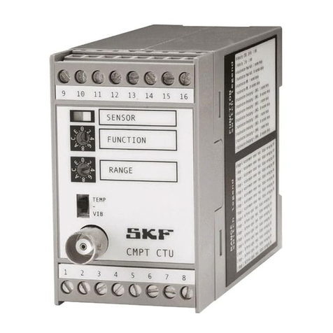
SKF CMSS500 Series User manual

SKF Machine Condition
Transmitter (MCT)
CMSS500(A) Series
User Manual Part No. 32031400-EN
Revision C
User Manual
Copyright©2007
by SKF Reliability Systems
All rights reserved.
5271 Viewridge Court
San Diego, CA 92123-1841 USA
Telephone: (858) 496-3400
Fax: (858) 496-3531
Customer Service: 1-800-523-7514
주식회사 광 호
T. 061-684-2136
F. 061-684-2137

SKF Reliability Systems
5271 Viewridge Court
San Diego, California 92123 USA
Telephone (858) 496-3400
FAX (858) 496-3531
For technical support, contact:
or
(Europe, Middle East, and Africa)
Visit us at our web site:
www.skf.com/cm
SKF Patents include: #US05854553, #US05845230, #US06489884,
#US05679900, #US04768380, #US06199422, #US05992237,
#US06202491, #US06513386, #US06275781, #US06633822,
#US06006164, #US2003_0178515A1, #US6,789,025, #US6,789,360,
#WO_03_048714A1
® SKF is a registered trademark of the SKF Group
010207jj

SKF Reliability Systems
Limited Warranty
WARRANTY
Subject to the terms and conditions contained herein, SKF warrants to the
Buyer that for the warranty period indicated below the products sold by SKF
that are listed below (the "Products"), when properly installed, maintained and
operated, will be free from defects in material and workmanship and shall be
fit for the ordinary purposes for which the Products are designed.
BUYER'S LIMITED REMEDIES
This limited warranty defines SKF's sole and exclusive liability and Buyer's sole
and exclusive remedy for any claim arising out of, or related to, any alleged
deficiency in any Product sold by SKF, even if such claim is based on tort
(including negligence or strict liability), breach of contract, or any other legal
theory.
If the Product does not conform to this limited warranty, Buyer must notify
SKF or SKF's authorized service representative within thirty (30) days of
discovery of the nonconformity; provided, however, that SKF shall not be liable
for any claim for which notice is received by SKF more than thirty (30) days
following the expiration of the applicable warranty period for the Product.
Upon receipt of timely notification from Buyer, SKF may, at its sole option,
modify, repair, replace the Product, or reimburse Buyer for any payment
made by Buyer to SKF for the purchase price of the Product, with such
reimbursement being pro rated over the warranty period.
WARRANTY PERIOD
Except as expressly provided below, the warranty period for each Product
shall commence on the date the Product is shipped by SKF to Buyer.

90-DAY WARRANTY
Products warranted for ninety (90) days by SKF are as follows: cable
assemblies, MARLIN(r) QuickConnect (MQC), magnetic temperature probes,
and all refurbished equipment.
ONE-YEAR WARRANTY
Products warranted for one (1) year by SKF are as follows: all Microlog(r)
products and accessories, all MARLIN(r) data managers (MDM), all MARLIN(r)
Condition Detectors (MCD), all Multilog Condition Monitoring Units (CMU),
Multilog Local Monitoring Units (LMU), all Vibration PenPlus, all transmitters,
all SKF software, all Monitor Interface Modules (MIM), all Machine Condition
Transmitters (MCT), MicroVibe P and Custom Products with the prefix of
CMCP (with the exception of any consumable or expendable items).
TWO-YEAR WARRANTY
Products warranted for two (2) years by SKF are as follows:
All standard Eddy Probes, Eddy Probe Drivers, and Eddy Probe Extension
Cables, all standard seismic sensors (accelerometers and velocity transducers),
and all M800A and VM600 Machinery Monitoring Systems.
For all On-Line Systems that have satisfied Criteria 1 and 2 below, the
warranty period shall be either thirty (30) months from the date the On-Line
System is shipped by SKF to Buyer, two (2) years from the date the On-Line
System is installed and commissioned by SKF, or two (2) years from the date
on which the installation of the On-Line System has been audited and
commissioned by SKF or its authorized service representative, whichever
period ends first.

Criteria 1.
Devices used with a Multilog Condition Monitoring Unit (CMU), Multilog Local
Monitoring Unit (LMU), including, but not limited to, the sensing device, the
interconnect cabling, junction boxes, if any, and the communications interface,
must consist only of SKF-supplied or SKF-approved devices and/or
components. The computer provided by Buyer must meet the requirements
stipulated by SKF.
Criteria 2.
SKF or its authorized service representative has installed the On-Line System
or has audited the installation and commissioned the On-Line System.
"On-Line Systems" are defined as systems consisting of Multilog Condition
Monitoring Unit(s) (CMU), Multilog Local Monitoring Unit(s) (LMU), and any
sensing or input devices, the interconnect cabling between the sensing or
input devices and the Multilog Condition Monitoring Unit(s) (CMU), Multilog
Local Monitoring Unit(s) (LMU), and the cabling between the Multilog
Condition Monitoring Unit (CMU), Multilog Local Monitoring Unit (LMU) and
the proprietary SKF communications interface with the host computer.
OTHER SKF PRODUCTS
Any SKF product supplied hereunder but not covered by this limited warranty
shall be either covered by the applicable SKF limited warranty then in place
for such product or, if no such warranty exists, shall be covered by the 90-day
warranty stated above.
THIRD PARTY PRODUCT WARRANTIES
For any third party products sold to Buyer by SKF, SKF will transfer to Buyer
any warranties made by the applicable third party product vendor to the
extent such warranties are transferable.
CONDITIONS

As a condition to SKF's warranty obligations hereunder and if requested or
authorized in writing by SKF, Buyer shall forward to SKF any Product claimed
by Buyer as being defective. Buyer shall prepay all transportation charges to
SKF's factory or authorized service center. SKF will bear the cost of shipping
any replacement Products to Buyer. Buyer agrees to pay SKF's invoice for
the then-current price of any replacement Product furnished to Buyer by
SKF, if the Product that was replaced is later determined by SKF to conform
to this limited warranty.
SKF shall not be obligated under this limited warranty or otherwise for normal
wear and tear or for any Product which, following shipment and any
installation by SKF (if required by the contract with the Buyer), has, in SKF's
sole judgment, been subjected to accident, abuse, misapplication, improper
mounting or remounting, improper lubrication, improper repair or alteration,
or maintenance, neglect, excessive operating conditions or for defects caused
by or attributable to the Buyer, including without limitation Buyer's failure to
comply with any written instructions provided to Buyer by SKF.
SKF shall be free to conduct such tests, investigations and analysis of the
Products returned to SKF, as it deems reasonable and proper in the exercise
of its sole judgment. As a further condition to SKF's obligations hereunder,
Buyer shall offer its reasonable cooperation to SKF in the course of SKF's
review of any warranty claim, including, by way of example only, Buyer's
providing to SKF any and all information as to service, operating history,
mounting, wiring, or re-lubrication of the Product which is the subject of the
Buyer's warranty claim.
EXCEPT WARRANTY OF TITLE AND FOR THE WARRANTIES EXPRESSLY SET
FORTH IN HEREIN, IT IS UNDERSTOOD AND AGREED THAT: (a) SKF MAKES
NO OTHER WARRANTY, REPRESENTATION OR INDEMNIFICATION, EITHER
EXPRESS OR IMPLIED, INCLUDING WITHOUT LIMITATION ANY IMPLIED
WARRANTY OF MERCHANTABILITY, FITNESS FOR A PARTICULAR PURPOSE,
OR NON-INFRINGEMENT; (b) IN NO EVENT SHALL SKF BE LIABLE OR
OBLIGATED FOR SPECIAL, EXEMPLARY, PUNITIVE, INCIDENTAL, DIRECT,

INDIRECT, GENERAL OR CONSEQUENTIAL DAMAGES (INCLUDING, BY WAY
OF EXAMPLE ONLY, LOST PROFITS OR SAVINGS, LOSS OF BUSINESS OR
LOSS OF USE) OR ANY OTHER LOSS, COST OR EXPENSE IN CONNECTION
WITH THE PRODUCTS AND RELATED SERVICES, IF ANY, PROVIDED BY SKF,
AND THIS DISCLAIMER SHALL EXTEND AS WELL TO ANY LIABILITY FOR
NONPERFORMANCE CAUSED BY SKF'S GROSS OR ORDINARY NEGLIGENCE,
AND IN ALL CASES REGARDLESS OF WHETHER OR NOT ANY OF THE
FOREGOING WERE FORESEEABLE OR THAT SKF WAS ADVISED AS TO THE
POSSIBILITY OF SUCH DAMAGES, LOSS, COST, OR EXPENSE; AND (c) NO
PERSON HAS BEEN AUTHORIZED BY SKF TO MAKE ANY FURTHER OR
CONTRARY INDEMNITIES, REPRESENTATIONS OR WARRANTIES ON
BEHALF OF SKF. THE FOREGOING LIMITATIONS AND DISCLAIMERS OF
LIABILITY SHALL BE MADE APPLICABLE TO THE SALE OF ANY PRODUCT BY
SKF TO THE FURTHEST EXTENT PERMITTED BY APPLICABLE LAW.
The exclusive remedies provided in this limited warranty shall not be deemed
to have failed of their essential purpose so long as SKF is willing and able to
perform to the extent and in the manner prescribed in this limited warranty.
CM-F0001
(Revision N, 11-04)


SKF Machine Condition Transmitter TOC- 1
User Manual
Contents
Introduction 1
The MCT Transmitter ..................................................... 1
The MCT Monitor............................................................. 3
Identification Label........................................................... 6
Powering the MCT........................................................... 8
CMSS500 Series Transmitters 1
Overview ............................................................................ 1
Jumpers ............................................................................. 7
Output...............................................................................15
CMSS500 Series Monitor 1
Setting Monitor Alarms .................................................. 1
Alert and Danger Alarm Setpoint Adjustment.......... 1
Alert and Danger Alarm Delays Adjustment ............. 4
Latching / Non-latching Alarms ................................... 6
Trip Multiply ...................................................................... 7
Alarm Relays..................................................................... 8
Installing the Machine Condition Transmitter 1
MCT Typical Installation ................................................. 1
Opening the Case............................................................. 2
Interfacing the MCT with Other Monitoring Systems4

TOC - 2 SKF Machine Condition Transmitter
User Manual
Analyzing MCT Readings................................................ 6
Peak-to-Peak Measurements with the Microlog
(Acceleration and Enveloped Acceleration) ................ 7
RMS Measurements with the Microlog (Acceleration
and Velocity)...................................................................... 8
Peak Detection in Velocity.............................................. 8
CE Installation Guide 1
Overview............................................................................. 1
CE Installation Drawings ................................................ 2
CE Installation ................................................................... 4
Mounting and Outline 1
CMSS500A ........................................................................ 1
CMSS500........................................................................... 2
General Severity Level Guidelines 1
Vibration measured in Velocity..................................... 1
Vibration Enveloped Acceleration Measurements.... 4

SKF Machine Condition Transmitter 1- 1
User Manual
1
Introduction
SKF Reliability Systems' Machine Condition Transmitter
(MCT) modules are compact rail-mounted devices that
convert part of a wide-band input signal to a signal
proportional to machine vibration.
The MCT Transmitter
There are six MCT versions, the CMSS525 is an RMS
acceleration transmitter, the CMSS530 is a velocity
transmitter, the CMSS540 is a displacement transmitter,
the CMSS545 is a position transmitter, the CMSS570 is a
temperature transmitter, and the CMSS590 is an
enveloped acceleration transmitter.
Output is a standard 4-20 mA current proportional to
this level, within a specified full range such as 0-1 IPS
RMS for velocity, or 0-10 gE for enveloped acceleration.
The 4-20 mA output is suitable for a direct connection to
a Programmable Logic Controller (PLC) or Distributed
Control System (DCS). A BNC connector on the front of
the unit provides access to the buffered transducer signal
for use with portable monitoring equipment, such as the
SKF Microlog®Series Data Collector / Analyzer.

Introduction
The MCT Transmitter
1- 2 SKF Machine Condition Transmitter
User Manual
Figure 1 - 1.
The MCT - Transmitter.
Figure 1 - 2.
The MCT - Transmitter/Monitor.

Introduction
The MCT Monitor
SKF Machine Condition Transmitter 1- 3
User Manual
The MCT Monitor
CMSS525- RMS Acceleration Transmitter without Monitor
CMSS525A RMS Acceleration Transmitter with Monitor
CMSS530- Velocity Transmitter without Monitor
CMSS530A Velocity Transmitter with Monitor
CMSS540- Displacement Transmitter without Monitor
CMSS540A Displacement Transmitter with Monitor
CMSS545- Position Transmitter without Monitor
CMSS545A Position Transmitter with Monitor
CMSS570- Temperature Transmitter without Monitor
CMSS570A Temperature Transmitter with Monitor
CMSS590- Enveloped Acceleration Transmitter without Monitor
* * CMSS590A Enveloped Acceleration Transmitter with Monitor
Table 1 - 1.
MCT Module Configurations.
MCT modules can be ordered as stand alone Monitors by
adding the suffix "A" to the basic model number (i.e.,
CMSS530A or CMSS590A). When ordered as a stand
alone monitor, the unit includes an alarm module front
panel and output relays that can be jumper configured
for either latching or non-latching operation. The ALERT
or DANGER LED will turn "ON" and the corresponding
relay will actuate whenever overall vibration levels exceed
the corresponding setpoint for more than a preset delay
time (jumper selectable). The alarm module has a front
panel accessible BNC connector and associated selector
switch for reading the analog current vibration level (CV)
or alarm setpoints (A or D) with a standard digital
voltmeter. The alarm module also provides a transducer
OK relay contact, and a trip multiply function (Tx). Trip
multiply allows the alarm levels to be temporarily

Introduction
The MCT Monitor
1- 4 SKF Machine Condition Transmitter
User Manual
increased by a factor of two or three to avoid false
alarms, for example, during the start-up phase of a
machine.
Figure 1 - 3.
MCT Transmitter General Pin Assignment.

Introduction
The MCT Monitor
SKF Machine Condition Transmitter 1- 5
User Manual
Figure 1 - 4.
MCT Transmitter / Monitor General Pin Assignment.
Figure 1 - 5.
MCT Transmitter / Monitor Top and Bottom Pluggable Terminals.

Introduction
Identification Label
1- 6 SKF Machine Condition Transmitter
User Manual
Both monitors and transmitters mount on standard DIN
rail, either G-rail or T-rail.
For more information concerning the alarm settings,
reference Setting Monitor Alarms in Chapter 3.
Identification Label
An identification label on the right side of the module
provides information about the module type including a
unique model number identifying data of the module's
basic configuration, such as the factory configured sensor
type, the measurement method and the installed filter
characteristics.
Standard MCT Units

Introduction
Identification Label
SKF Machine Condition Transmitter 1- 7
User Manual

Introduction
Powering the MCT
1- 8 SKF Machine Condition Transmitter
User Manual
Each enveloped acceleration transmitter provides three
band-pass filters.
Special Velocity Units
The unique serial number identifies individual
transmitters and is used for warranty, quality control, and
service purposes. The label also has the CSA and CE
approval marks.
Powering the MCT
The MCT requires externally supplied dc power. The
selected power supply should have a nominal output of
+24 Vdc and be capable of supplying minimum currents
noted in Table 1-2:
Model
Number Minimum Power
Supply/Unit
CMSS525-
CMSS530-
CMSS540-
55 mA

Introduction
Powering the MCT
SKF Machine Condition Transmitter 1- 9
User Manual
CMSS545-
CMSS570-
CMSS525A
CMSS530A
CMSS540A
CMSS545A
CMSS570A
110 mA
CMSS590- 75 mA
CMSS590A 125 mA
Table 1 - 2.
MCT Maximum Currents.
* Average current requirements are usually lower.
A regulated power supply dedicated to the vibration
monitoring system is recommended. It is also
recommended that connections between the power-
supply and the transmitter/monitors be made with
shielded twisted instrument cable. The cable shield
should float at the transmitter/monitor, and connect to
ground at the power supply / system common end only.
The MCT regulates dc power internally to prevent a fault
on the output of one channel from affecting other
channels. When power is first applied to a
transmitter/monitor after connecting the transducer, a
delay of approximately 30 seconds will occur before the
OK LED turns "ON".
Power Supply Distribution
If more than one MCT module is installed, terminal blocks
for power and ground should be used. From these
terminal blocks, 24 Vdc power is distributed to each
individual module. It is recommended to use individual
fuse terminals for each positive supply line so a power

Introduction
Powering the MCT
1- 10 SKF Machine Condition Transmitter
User Manual
failure in a single MCT module will not affect the other
modules.
Figure 1 - 6.
Typical Power Wiring Configuration.
Grounding
When experiencing interference on the output signals due
to common ground connections, it is recommended to
connect the +24 V GND at the power distribution
terminals to the protective ground (PE).
For CE-approved systems, it is recommended to use
shielded twisted pair cables for all signal connections.
Except for the sensor signal (for example, accelerometer),
all shields must be connected to PE.
This manual suits for next models
11
Table of contents
Other SKF Transmitter manuals
Popular Transmitter manuals by other brands

Endress+Hauser
Endress+Hauser iTEMP TMT71 Safety instructions

Nautel
Nautel GV60 troubleshooting manual

PCB
PCB EX1503M42 Installation and operating manual

Burk
Burk Plus-X 300 Installation and operation manual

HumanTechnik
HumanTechnik lisa combi II operating instructions

Bellman & Symfon
Bellman & Symfon BE1490 user guide