APG PT-500 Series User manual

APG
R
Doc #9003999
Rev A1, 08/16
PT-500 Modbus Series
User Manual

ii Tel: 1/888/525-7300 • Fax: 1/435/753-7490 • www.apgsensors.com • [email protected]
Table of Contents
Introduction ................................................................................................................ iii
Warranty and Warranty Restrictions.................................................................... iv
Chapter 1: Specications and Options..................................................................... 1
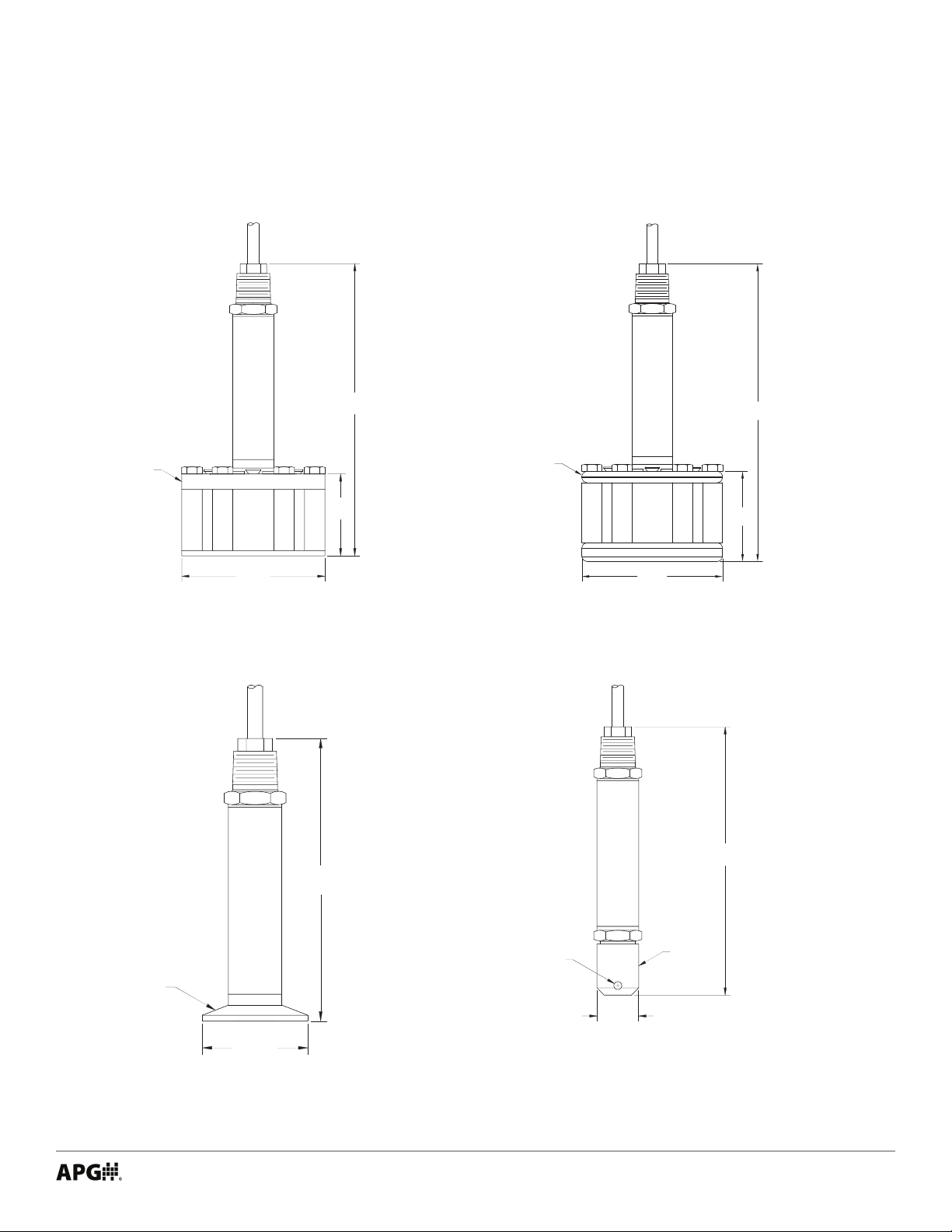
Dimensions ........................................................................................................................................1
Specications ................................................................................................................................... 2
Model Number Congurator.......................................................................................................... 3
Electrical Pinout Table, Power Supply Table, and System Wiring Diagrams..................... 4
Chapter 2: Installation and Removal Procedures and Notes..............................5
Tools Needed..................................................................................................................................... 5
Mounting Instructions ................................................................................................................... 5
Electrical Installation ..................................................................................................................... 5
Removal Instructions ..................................................................................................................... 6
Chapter 3: Programming ............................................................................................6
Modbus Programming .................................................................................................................... 6
Modbus Programming with RST-6001 and APG Modbus Software ...................................... 6
PT-500 Modbus Register Lists .................................................................................................. 7-9
PT-500 Modbus Sensor Parameters - L5 pressure series...................................................... 10
PT-500 Modbus Sensor Parameters - L31 level series ........................................................... 10
PT-500 Modbus Application Parameters - L31 level series ............................................. 11-15
Chapter 4: Maintenance ...........................................................................................16
General Care.................................................................................................................................... 16
Vent Tube Drying......................................................................................................................16-17
Repair and Returns........................................................................................................................ 17
NOTE: Wiring information in this User Manual is specic to the Modbus Series of the
PT-500. If you have a 0-5V, mV/V, or 4-20 mA Series sensor, please consult the factory at
1-888-525-7300, or our website at www.apgsensors.com/support, for the appropriate
manual for your sensor.

iii
Introduction
Thank you for purchasing a PT-500 modbus series submersible pressure transmitter from APG. We
appreciate your business! Please take a few minutes to familiarize yourself with your PT-500 and this
manual.
PT-500 submersible pressure transmitters oer reliability in harsh industrial conditions. The small size,
integrated electronics, wide operating temperature range, and durability make the PT-500 the perfect
instrument for static and dynamic pressure measurement.
Reading your label
Every APG instrument comes with a label that includes the instrument’s model number, part number, serial
number, and a wiring pinout table. Please ensure that the part number and pinout table on your label
match your order.

iv Tel: 1/888/525-7300 • Fax: 1/435/753-7490 • www.apgsensors.com • [email protected]
Warranty and Warranty Restrictions
This product is covered by APG’s waranty to be free from defects in material and workmanship under
normal use and service of the product for 24 months. For a full explanation of our Warranty, please visit
https://www.apgsensors.com/about-us/terms-conditions. Contact Technical Support to recieve a Return
Material Authorization before shipping your product back.
Scan the QR code below to read the full explanation of our Warranty on your tablet or smartphone.

1
Chapter 1: Specications and Options
• Dimensions
PT-500 with Reusable Cage
PT-500 with Removable Plastic
Nose Cone
PT-500 with Tri-clover
Sanitary Fitting
[88.9mm]
ø3.50"
REMOVABLE
SENSOR CAGE
ASSEMBLY
7.14"
[181.3mm]
2.00"
[50.8]
6.44"
[163.5mm]
ø.188 THRU
PROTECTIVE
CONE
[25.4mm]
ø1.00"
1 1/2"
SANITARY
FITTING
[50.3mm]
ø1.98"
5.29"
[134.4mm]
7.40”
[187.9mm]
2.24”
[56.9mm]
ø3.50”
[88.9mm]
NON-REMOVABLE
SENSOR CAGE
ASSEMBLY
PT-500 with Welded Anti-snag Cage

2Tel: 1/888/525-7300 • Fax: 1/435/753-7490 • www.apgsensors.com • [email protected]
Performance
Pressure Ranges 0 to 300 PSIG
Digital Output Modbus RTU, 4-wire RS-485
Over Pressure 2X FSO
Burst Pressure 3.0X FSO
1 Year Stability 0.75% FSO
Accuracy
Linearity, Hystereses & Repeatability ±0.25% of Full Scale (BFSL) up to ±0.1% of Full Scale
Thermal Zero Shift @ 70 °F ±0.045% FSO/°C (±0.025% FSO/°F)
Thermal Span Shift @ 70 °F ±0.045% FSO/°C (±0.025% FSO/°F)
Environmental
Operating Temperature -40 to 85°C (-40 to 185°F)
Compensated Temperature -17 to 54°C (0 - 130°F)
Maximum Submersible Depth 462.2 ft / 140.88 m / 300 psig
Electrical
Supply Voltage (at sensor) 5-28 VDC
Current Draw 2 mA max.
Protection Reverse Polarity and Surge (per IEC 61000-4-5)
Load Limitation R(max) = ((Vs-12V)/0.02A)-(0.042Ω per ft. of cable)
Startup Time 200 ms
Materials of Construction
Wetted Materials 316L Stainless Steel
Anti-snag Cage 316L Stainless Steel
Cable Urethane, PVC, or Hytrel
Protective Nose Cone Delrin
Seal Viton ETP-s
Mechanical
Pressure Connection See model number congurator for complete list
Cable Tensile Strength Up to 200 pounds
Patents
US Patent No. 7,787,330
• Specications

3
• Model Number Congurator
Part Number: PT-500_____ - _____ - _____ - _____ - _____ - _____ - _____ - _____
A B C D E F G H
A. Cable Type
□ -▲ Urethane - Blue (with vent tube)
□A PVC - Black (no vent tube - sealed unit)
□B Hytrel .31” Ø - Black (with vent tube)
□C PVC - Black (with vent tube)
□D Hytrel .25” Ø - Black (with vent tube)
B. Pressure Range
□Specify range in desired unit of measure
__________ Max Water Depth
462.2 ft. (140.9 m), 300 psig
C. Standard Units of Measure
□PSI □FTH2O □INWC
□INH2O □MMH2O □FWC
D. Output
□L1▲ 4-20 mA, 2-wire
□L3 0-5V, 4-wire*
□L9 mV/V, 4-wire*
□L10 0-10V, 4-wire*
□L5 Modbus RTU, 4-wire RS-485*
Pressure reading only
□L31 Modbu RTU, 4-wire RS-485*
Level calculations, tank volume
E. NPTM
□E0▲ 1/2” NPTM tting for conduit, with pigtail
□E5 Pigtail without conduit connection
F. Process Connection
□P1▲ 1/2” NPTM with removable plastic nose cone
□P5 1/4” NPTF
□P37 Welded Cage (anti-snag 1 piece tting)
□P38 1-1/2” tri-clover with 3/4” diaphragm
□P39 Reusable Cage (includes P38 tting)
G. Cable Length
□(specify length of cable needed in feet)
H. Accuracy
□N0▲ ±0.25%
□N1 ±0.25% with NIST certication
□N2 ±0.1% with NIST certication
Note: ▲Indicates this option is standard.
Note: *Indicates this option does not yet have CSA
Approvals.

4Tel: 1/888/525-7300 • Fax: 1/435/753-7490 • www.apgsensors.com • [email protected]
• Electrical Pinout Table, Supply Power Table, and System Wiring Diagrams
Pigtail
Modbus
Red + Power
Black - Power
Green B (TX-)
White A (TX+)
Shield Case Gnd
Modbus
Power Supply 5-28 VDC
Power
Supply
+5-28 Vdc
GND Use Shielded Cable
120 Ω
terminating
resistor
120 Ω terminating
resistor at last sensor
V+
B (TX-)
A (TX+)
Sensor 1
GND
V+
B (TX-)
A (TX+)
Sensor 2
GND
V+
B (TX-)
A (TX+)
Sensor 3
GND
Master
Device
RS-485 A (TX+)
RS-485 B (TX-)
PT-500 modbus
series sensor
PT-500 modbus
series sensor
PT-500 modbus
series sensor
Note: PT-500 modbus sensors use
reversed TX+/TX- pins. When connecting
to your system, ensure continuity
of TX- to TX- and TX+ to TX+, rather than
A to A and B to B.
Power
Supply
+5-28 Vdc
GND Use Shielded Cable
Equivalent 120 Ω
terminating resistor
internal to RST-6001
120 Ω terminating
resistor at last sensor
USB to computer
with APG Modbus
software
RST-6001
Modbus
Controller
V+
B
A
Sensor 1
GND
V+
B
A
Sensor 2
GND
V+
B
A
Sensor 3
GND
A
B
-5V
PT-500 modbus
series sensor
+5V
PT-500 modbus
series sensor
PT-500 modbus
series sensor
Note: An independent +5-28 Vdc
power supply is required when using
an RST-6001 Modbus Controller. The
RST-6001 can only supply ±5 Vdc, not
the +5-28 Vdc required by the modbus
series PT-500.
Modbus System Wiring with RST-6001
Modbus System Wiring
PT-500 Modbus Series Pinout Table PT-500 Modbus Series Supply Power Table

5
Chapter 2: Installation and Removal Procedures and Notes
• Mounting Instructions
Your PT-500 can be mounted in three ways: via NPT process connection, free-hanging suspension, or con-
duit mounted. Mounting your pressure transducer is easy if you follow a few simple steps:
• Never over-tighten the sensor. In all cases, tighten the sensor as little as possible to create an adequate
seal.
• Always use thread tape or sealant compound on tapered threads. Wrap thread tape in the opposite
direction of the threads so it does not unravel as you screw the sensor into place. Unraveling can cause
uneven distribution and seal failure.
• Always start screwing in your sensor by hand to avoid cross-threading. Thread failure can be a problem
if you damage threads by over-tightening them or by crossing threads.
• For suspension mounting the PT-500, drill a 3/16” hole into the 1/2” NPTF to 1/2” NPTF hex coupler
(P/N 511414) and secure it to the 1/2” NPTM coupler tting of the PT-500. Attach a .060” diameter 316L
SS cable of desired length to the hex coupler and secure the steel cable according to your application
requirements.
• Wrench sized appropriately for your PT-500’s process or conduit connection.
• Thread tape or sealant compound for threaded connections.
• Tools Needed
• Attach the wires of your PT-500 to your control system according to the pinout table above.
• Electrical Installation
IMPORTANT: APG modbus equipment uses reversed TX+/TX- pins. When making
connections between APG equipment, ensure continuity of A to A and B to B pins. When
connecting APG modbus equipment to other systems, ensure continuity of TX+ to TX+
and TX- to TX-.
NOTE: If your PT-500 has a vent tube, do not seal, cover, or close the vent tube with
anything other than an APG-provided venting cap or desiccant drying cartridge (See Fig-
ure 4.1 and 4.2). Unapproved seals or covers will prevent proper sensor operation.

6Tel: 1/888/525-7300 • Fax: 1/435/753-7490 • www.apgsensors.com • [email protected]
Removing your PT-500 from service must be done with care. It’s easy to create an unsafe situation, or
damage your sensor, if you are not careful to follow these guidelines:
• For sensors installed via NPT process connection, make sure the pressure is completely removed from
the line or vessel. Follow any and all procedures for safely isolating any media contained inside the line
or vessel.
• Remove the sensor with an appropriately sized wrench (per your process connection).
• For suspended sensors, retrieve the sensor from the vessel. Follow any and all procedures for safely
isolating any media contained inside the line or vessel.
• Carefully clean the sensor’s tting and diaphragm of any debris (see General Care) and inspect for
damage.
• Store your sensor in a dry place, at a temperature between -40° F and 180° F.
• Removal Instructions
DANGER: Removing your process connected PT-500 Pressure Transmitter while there
is still pressure in the line could result in injury or death.
PT-500 L5/L31 modbus series sensors use standard Modbus RTU protocol (RS-485). The sensors can only op-
erate as slave devices. Sensor default transmission settings are 9600 Baud, 8 Bits, 1 Stop Bit, No Parity, and
require a minimum delay of 300 ms between transactions to return the contents of all registers. Commands
returning fewer registers will require shorter delays. See PT-500 Modbus Register Lists on pages 7 - 9.
Chapter 3: Programming
• Modbus Programming
NOTE: For more information about Modbus RTU, please visit www.modbus.org.
IMPORTANT: Any contact with the diaphragm can permanently damage the sensor.
Use extreme caution.

7
APG RST-6001 Modbus Controller can be used in tandem with APG Modbus to program and control up to 20
PT-500 L5 or PT-500 L31 sensors. Through APG Modbus, you can monitor the raw readings from the sensor,
including level or pressure, temperature and battery voltage, or congure the sensor. See PT-500 Modbus
Register Lists on pages 7 - 9.
• Modbus Programming with RST-6001 and APG Modbus Software
NOTE: For APG Modbus programming instructions, or to download APG Modbus soft-
ware, please visit www.apgsensors.com/support.
• PT-500 Modbus Register Lists
Input Registers (0x04)
Register Returned Data
30299 Model Type
30300 Pressure (L5 - PSI; L31 - mmH2O)
30301 N/A
30302 Temperature Reading (in 0C, signed)
30303-30304 Calculated (raw)
30305-30306 N/A
30307 N/A
30308 Battery Voltage
30309 Trip 1 Status
30310 Trip 2 Status
NOTE: The Calculated Readings will be returned without a decimal place. In order to
obtain the true result, the Decimal Place setting must be taken into account.

8Tel: 1/888/525-7300 • Fax: 1/435/753-7490 • www.apgsensors.com • [email protected]
Holding Registers (0x03) - PT-500 L5 pressure series
Register Function Value Range
40400 Device Address 1 to 247
40401 Units 0-16
40402 Application Type 0 or 8
40403 N/A
40404 Decimal (Calculated) 0 - 3
40405 Max Pressure *0 - 32,000 PSI
40406 Full Pressure 0 - 32,000 PSI
40407 Zero Oset -15,000 - 30,000 PSI
40408 Pressure Decimal 0 - 3
40409 A/D Gain *1, 2, 4, 8, 16, 32, 64, 128
40410 N/A
40411 Parameter Default 0 = No; 1 = Restore Defaults
40412 Averaging 0 - 10
40413 Calibration Value *-32,767 - 32,767
40414 Calibration Flag *0 - 300
40415 Sample Rate 10 to 1000 milliseconds
40416 Scale *0 - 65,535
40417 Oset -20,000 - 20,000
40418 Voltage Oset -20 - 20
40419 Baud Rate 0 - 3 (2400, 9600, 19200)
40420 Parity 0 - 2 (none, even, odd)
40421 Stop Bit 0 - 1 (0 = 1 stop bit; 1 = 2 stop bits)
40422-40423 Pressure X^3 *N/A
40424-40425 Pressure X^2 *N/A
40426-40427 Pressure X^1 *N/A
40428-40429 Pressure X^0 *N/A
40430 Trip 1 Pressure -15,000 - 30,000 PSI
40431 Trip 1 Window 0 - 30,00 PSI
40432 Trip 1 Type 0 - 29
40433 Trip 2 Pressure -15,000 - 30,000 PSI
40434 Trip 2 Window 0 - 30,00 PSI
40435 Trip 2 Type 0 - 29
40436-40437 Multiplier 0.0010 - 99.9999 (oat)
40438-40439 Description A - Z, 0 - 9, /.-,+* (16 char)
40446 Temperature Oset -20 - 20
40447-40448 Temperature X^3 *N/A
40449-40450 Temperature X^2 *N/A
40451-40452 Temperature X^1 *N/A
40453-40454 Temperature X^0 *N/A
*Setting is factory calibrated. Do not adjust.

9
Holding Registers (0x03) - PT-500 L31 level series
Register Function Value Range
40400 Device Address 1 to 247
40401 Units 1 = Feet, 2 = Inches, 3 = Meters
40402 Application Type 0 - 11
40403 Volume Units 1 - 7
40404 Decimal (Calculated) 0 - 3
40405 Max Level *0 - 65,535 mm
40406 Full Level 0 - 65,535 mm
40407 Zero Oset 0 - 610 mm
40408 N/A
40409 A/D Gain *1, 2, 4, 8, 16, 32, 64, 128
40410 Specic Gravity 1 - 2,000
40411 Parameter Default 0 = No; 1 = Restore Defaults
40412 Averaging 0 - 10
40413 Calibration Value *0 - 65,535
40414 Calibration Flag *0 - 300
40415 Sample Rate 10 to 1000 milliseconds
40416 Scale *0 - 65,535
40417 Oset -20,000 - 20,000
40418 Voltage Oset -20 - 20
40419 Baud Rate 0 - 3 (2400, 9600, 19200)
40420 Parity 0 - 2 (none, even, odd)
40421 Stop Bit 0 - 1 (0 = 1 stop bit; 1 = 2 stop bits)
40422-40423 Pressure X^3 *N/A
40424-40425 Pressure X^2 *N/A
40426-40427 Pressure X^1 *N/A
40428-40429 Pressure X^0 *N/A
40430 Trip 1 Level 0 - 65,535 (mm)
40431 Trip 1 Window 0 - 65,535 (mm)
40432 Trip 1 Type 0 - 29
40433 Trip 2 Level 0 - 65,535 (mm)
40434 Trip 2 Window 0 - 65,535 (mm)
40435 Trip 2 Type 0 - 29
40436-40437 Parameter 1 0 - 1,000,000 (mm)
40438-40439 Parameter 2 0 - 1,000,000 (mm)
40440-40441 Parameter 3 0 - 1,000,000 (mm)
40442-40443 Parameter 4 0 - 1,000,000 (mm)
40444-40445 Parameter 5 0 - 1,000,000 (mm)
40446 Temperature Oset -20 - 20
40447-40448 Temperature X^3 *N/A
40449-40450 Temperature X^2 *N/A
40451-40452 Temperature X^1 *N/A
40453-40454 Temperature X^0 *N/A
*Setting is factory calibrated. Do not adjust.

10 Tel: 1/888/525-7300 • Fax: 1/435/753-7490 • www.apgsensors.com • [email protected]
• PT-500 Modbus Sensor Parameters - L5 pressure series
40401 - Units
Determines the units of measure for the calculated reading.
0 = PSI 5 = mmH2O† 10 = mmHG‡14 = inSW
1 = BAR 6 = cmH2O† 11 = cmHG‡15 = inSW
2 = mBAR 7 = mH2O† 12 = inHG‡16 = mSW
3 = kPa 8 = inH2O†13 = kg/cm2
4 = MPa 9 = ftH2O†
† All H2O pressure measurements @ 20° C.
‡ All HG pressure measurements @ 0° C.
40402 - Application Type
Determines the units of measure for the calculated reading.
0 = Standard (units selected in 40401 are displayed)
8 = Custom (units selected in 40401 and multiplier in 40436-40437 are used to compute desired
units; description in 40438-40439 is label for measurement)
• PT-500 Modbus Sensor Parameters - L31 level series
40401 - Units
Determines the units of measure for the calculated reading when Application Type is set to 0, 1, or 7.
1 = Feet 2 = Inches 3 = Meters
40402 - Application Type
Determines the type of calculated reading performed by the sensor.
0 = Distance
1 = Level
2 = Standing Cylindrical Tank with or without Hemispherical Bottom
3 = Standing Cylindrical Tank with or without Conical Bottom
4 = Standing Rectangular Tank with or without Chute Bottom
5 = Horizontal Cylindrical Tank with or without Spherical Ends
6 = Spherical Tank
7 = Pounds (Linear Scaling)
8 = N/A
9 = Vertical Oval Tank
10 = Horizontal Oval Tank
11 = Strapping Chart

11
40403 - Volume Units
Determines the units of measure for the calculated reading when Application Type is set to 2 - 6 or 9 -11.
1 = Feet35 = Liters
2 = Million Feet36 = Inches3
3 = Gallons 7 = Barrels
4 = Meters3
• PT-500 Modbus Application Parameters - L31 level series
Application 0 - Distance
Register Function Value Range
40400 Device Address 1 to 247
40401 Units 1 = Feet, 2 = Inches, 3 = Meters
40402 Application Type 0
40403 Volume Units --
40404 Decimal (Calculated) 0 - 3
Application 1 - Level
Register Function Value Range
40400 Device Address 1 to 247
40401 Units 1 = Feet, 2 = Inches, 3 = Meters
40402 Application Type 1
40403 Volume Units --
40404 Decimal (Calculated) 0 - 3
Application 2 - Volume of Standing Cylindrical Tank ±Hemispherical Bottom
Register Function Value Range
40400 Device Address 1 to 247
40401 Units --
40402 Application Type 2
40403 Volume Units 1 - 7
40404 Decimal (Calculated) 0 - 3
40405 Max Level (factory set)
40406 Full Level 0 - 65,535 mm
40436-40437 Tank Diameter 0 - 1,000,000 (mm)
40438-40439 Radius of Bottom Hemisphere 0 - 1,000,000 (mm)
Diameter
Full
Level
Bottom
Radius
or

12 Tel: 1/888/525-7300 • Fax: 1/435/753-7490 • www.apgsensors.com • [email protected]
Application 3 - Volume of Standing Cylindrical Tank ±Conical Bottom
Register Function Value Range
40400 Device Address 1 to 247
40401 Units --
40402 Application Type 3
40403 Volume Units 1 - 7
40404 Decimal (Calculated) 0 - 3
40405 Max Level (factory set)
40406 Full Level 0 - 65,535 mm
40436-40437 Tank Diameter 0 - 1,000,000 (mm)
40438-40439 Cone Diameter (at bottom of cone) 0 - 1,000,000 (mm)
40440-40441 Length (height) of Cone 0 - 1,000,000 (mm)
Application 4 - Volume of Standing Rectangular Tank ±Chute Bottom
Register Function Value Range
40400 Device Address 1 to 247
40401 Units --
40402 Application Type 4
40403 Volume Units 1 - 7
40404 Decimal (Calculated) 0 - 3
40405 Max Level (factory set)
40406 Full Level 0 - 65,535 mm
40436-40437 Tank X Dimension 0 - 1,000,000 (mm)
40438-40439 Tank Y Dimension 0 - 1,000,000 (mm)
40440-40441 Chute X Dimension 0 - 1,000,000 (mm)
40442-40443 Chute Y Dimension 0 - 1,000,000 (mm)
40444-40445 Length (height) of Chute 0 - 1,000,000 (mm)
Diameter
Full
Level
Cone
Length
Cone
Diameter
Tank X
Chute
Length
Tank Y
Full
Level
or
Chute Y
Chute X

13
Application 5 - Volume of Horizontal Cylindrical Tank ±Hemispherical Ends
Register Function Value Range
40400 Device Address 1 to 247
40401 Units --
40402 Application Type 5
40403 Volume Units 1 - 7
40404 Decimal (Calculated) 0 - 3
40405 Max Level (factory set)
40406 Full Level 0 - 65,535 mm
40436-40437 Tank Length 0 - 1,000,000 (mm)
40438-40439 Tank Diameter 0 - 1,000,000 (mm)
40440-40441 Radius of End Hemispheres 0 - 1,000,000 (mm)
Application 6 - Volume of Spherical Tank
Register Function Value Range
40400 Device Address 1 to 247
40401 Units --
40402 Application Type 6
40403 Volume Units 1 - 7
40404 Decimal (Calculated) 0 - 3
40405 Max Level (factory set)
40406 Full Level 0 - 65,535 mm
40436-40437 Tank Diameter 0 - 1,000,000 (mm)
Diameter
Length
Full
Level
End
Radius
Full
Level Diameter

14 Tel: 1/888/525-7300 • Fax: 1/435/753-7490 • www.apgsensors.com • [email protected]
Application 9 - Volume of Vertical Oval Tank
Register Function Value Range
40400 Device Address 1 to 247
40401 Units --
40402 Application Type 9
40403 Volume Units 1 - 7
40404 Decimal (Calculated) 0 - 3
40405 Max Level (factory set)
40406 Full Level 0 - 65,535 mm
40436-40437 Tank Length 0 - 1,000,000 (mm)
40438-40439 Tank Depth 0 - 1,000,000 (mm)
40440-40441 Tank Width 0 - 1,000,000 (mm)
Application 7 - Pounds (Linear Scaling)
Register Function Value Range
40400 Device Address 1 to 247
40401 Units 1 = Feet, 2 = Inches, 3 = Meters
40402 Application Type 7
40403 Volume Units --
40404 Decimal (Calculated) 0 - 3
40405 Max Level (factory set)
40406 Full Level 0 - 65,535 mm
40436-40437 Multiplier (linear scalar) 0 - 1,000,000 (1000 = 1.000)
Full
Level
Depth
Length
Width

15
Application 10 - Volume of Horizontal Oval Tank
Register Function Value Range
40400 Device Address 1 to 247
40401 Units --
40402 Application Type 10
40403 Volume Units 1 - 7
40404 Decimal (Calculated) 0 - 3
40405 Max Level (factory set)
40406 Full Level 0 - 65,535 mm
40436-40437 Tank Length 0 - 1,000,000 (mm)
40438-40439 Tank Depth 0 - 1,000,000 (mm)
40440-40441 Tank Width 0 - 1,000,000 (mm)
Application 11 - Strapping Chart (Polynomial Values)
Register Function Value Range
40400 Device Address 1 to 247
40401 Units 1 = Feet, 2 = Inches, 3 = Meters
40402 Application Type 11
40403 Volume Units 1 - 7
40404 Decimal (Calculated) 0 - 3
40405 Max Level (factory set)
40406 Full Level 0 - 65,535 mm
40436-40437 X^3 Coecient 0 - 1,000,000
40438-40439 X^2 Coecient 0 - 1,000,000
40440-40441 X^1 Coecient 0 - 1,000,000
40440-40441 X^0 Coecient 0 - 1,000,000
Length
Width
Depth
Full
Level

16 Tel: 1/888/525-7300 • Fax: 1/435/753-7490 • www.apgsensors.com • [email protected]
Condensation in the vent tube can damage the electronics in your sensor, resulting in unreliable readings.
APG oers two methods of preventing vent tube condensation: a venting cap, and a desiccant drying
cartridge.
The venting cap is a PVC tube with a hydrophobic patch that allows moisture to pass out of the tube without
allowing water in (See Figure 4.1). The cap is sealed by an o-ring, and is easily installed in the eld.
The desiccant drying cartridge with vent tube adapter absorbs any moisture in the vent tube to keep vapor
from condensing (See Figure 4.2). The installation of the desiccant drying cartridge is quick and easy.
Common installation methods are cable tie, Velcro, and cable clamps.
• Vent Tube Drying
Your PT-500 series pressure transmitter is very low maintenance and will need little care as long as it is
installed correctly. However, in general, you should:
• For process connected sensors, keep the transmitter and the area around it generally clean.
• Avoid applications for which the transmitter was not designed, such as extreme temperatures, contact
with incompatible corrosive chemicals, or other damaging environments.
• Inspect the threads whenever you remove the transmitter from duty or change its location.
• Avoid touching the diaphragm. Contact with the diaphragm, especially with a tool, could permanently
shift the output and ruin accuracy.
• Clean the diaphragm or the diaphragm bore with extreme care. If using a tool is required, make sure it
does not touch the diaphragm.
Chapter 4: Maintenance
• General Care
IMPORTANT: Any contact with the diaphragm can permanently damage the sensor.
Use extreme caution.
IMPORTANT: Do NOT use desiccant cartridge in the presence of vapors or liquids con-
taining phosphate esters, synthetic lubricants, hydrocarbon solvents, methanol, acetone,
lacquer solvents, or other organics.
Other manuals for PT-500 Series
4
Table of contents
Other APG Transmitter manuals

APG
APG PT-405 Series User manual

APG
APG PT-400 Series User manual

APG
APG HU-L24 User manual

APG
APG True Echo PRS Series User manual

APG
APG True Echo GWR200 User manual

APG
APG PT-400 Series User manual

APG
APG PT-405 Series User manual

APG
APG PT-400 Series User manual

APG
APG PT-500 Series User manual

APG
APG PT-400 Series User manual
Popular Transmitter manuals by other brands

Dwyer Instruments
Dwyer Instruments One-Touch 616OT Series Installation and operating instructions

Cypress
Cypress CA-COMPAT Operation manual

WAREMA
WAREMA EWFS Operating and installation instructions

Oppermann Regelgeräte
Oppermann Regelgeräte DDS-AR984 Series manual

Retekess
Retekess TR509 user manual

JUMO
JUMO dTRANS T02 LCD operating manual