2
INDEX
1. Connections and adjustments p. 2
2. TRANSMITTERS p. 3 - 5
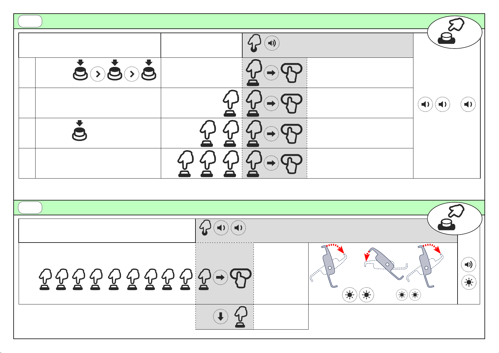
2.1 Radio codes memorization
2.2 Working time conguration
2.3 Radio codes deletion
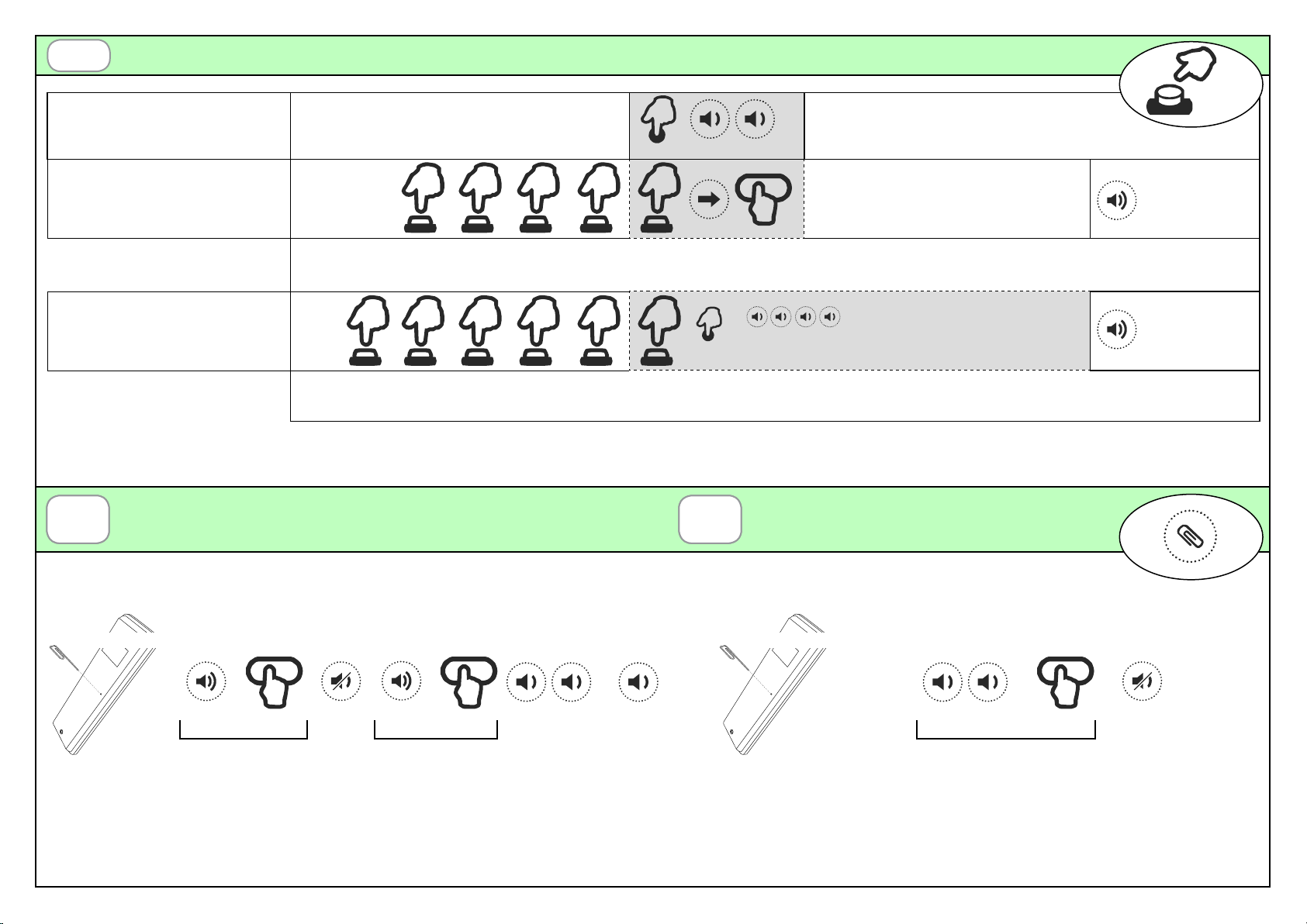
2.4 Remote memorization of other radio codes
2.5 Remote deletion of a radio code
3. SENSORS p. 6
3.1 WIND sensor
3.2 RAIN sensor
4. Technical specications p. 7
WARNINGS
The product at issue must be installed, commissioned and maintained only by licensed and authorised people, respecting the
laws concerning the automatic covers. The system is powered by 24Vdc. Before the connection to the power supply make sure
that the sensors and motors are correctly connected. A faulty connection of the motors (polarity inversion) could damage them
together with the connected mechanical elements. The power supply must supply the required voltage and current according
to the characteristics of the system. The power supply must be compliant with IEC60950-1 and must be protected against the
short-circuit and over-voltage. Use a 2x1.5mm cable to connect the motors and the control unit for length up to 6m, or 2x2.5mm
cable for longer segments.
PRODUCT DISPOSAL: at the end of this product’s useful life, it must not be disposed of as domestic waste, but must be taken
to a collection centre for waste electrical and electronic equipment.
Hereby Teleco automation s.r.l. declares that the product complies with the essential requirements and other relevant provisions,
established by the Directive 1999/5/EC. The declaration of conformity can be consulted on the web site: www.telecoautomation.com/ce.
In the view of a constant development of their products, the manufacturer reserves the right for changing technical data and
features without prior notice.
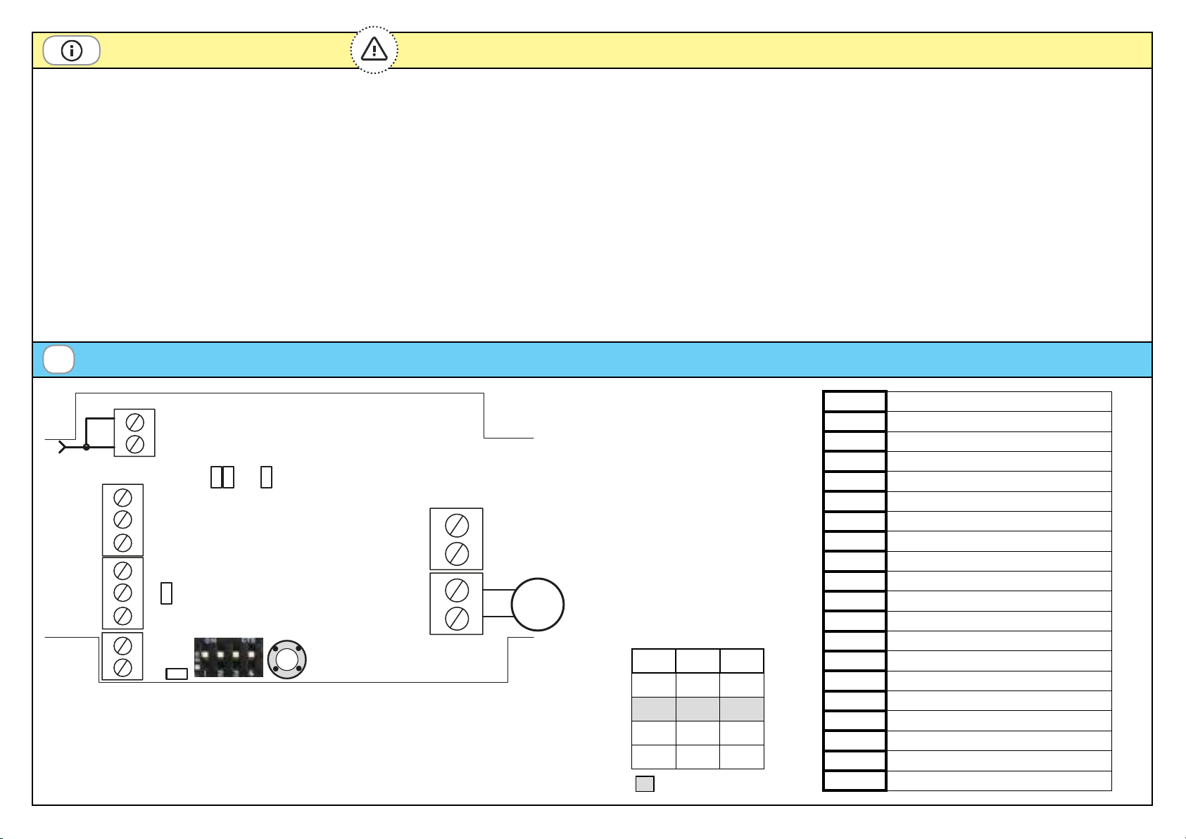
1Connections and adjustments
M
AN
LED
-
+
14
13
L1 L2 LM
24Vdc IN
16
15
DIP SWITCH
P1
1
2
5
6
7
8
9
10
11
12
RN
LED
DIP1 DIP2 (A)
OFF OFF 1
OFF ON 2
ON OFF 3
ON ON 4
Default
MOTOR STOPS. The control unit stops the motors at the point of a mechanical stop through
current absorption. The threshold can be set with DIP1 and DIP2 (table). Attention! Check
that the motor only stops at the mechanical stops (LM = ON): increase the threshold if
the motor stops during operation or decrease if the motor continues to push against the
mechanical stops.
1AERIAL GND
2AERIAL RF
5INPUTS COMMON
6HOLD-TO-RUN CLOSE INPUT (N.O.)
7HOLD-TO-RUN OPEN INPUT (N.O.)
8RAIN SENSOR (YELLOW, GND)
9RAIN SENSOR (BLUE, SIGNAL)
10 RAIN SENSOR (WHITE,+12V)
11 WIND SENSOR (BLUE)
12 WIND SENSOR (BROWN)
13 MOTOR (CLOSE)
14 MOTOR (OPEN)
15 +24Vdc POWER SUPPLY
16 POWER SUPPLY GND
AN LED WIND SENSOR PULSES
RN LED RAIN SENSOR ACTIVE
L1 ON = RAIN ALARM
L2 FLASHING = WIND ALARM
LM LIMIT SWITCH LED
P1 PROGRAMMING BUTTON