Vega VEGABAR 87 User manual

Operating Instructions
Submersible pressure transmitter with
metal measuring cell
VEGABAR 87
Modbus and Levelmaster protocol
Document ID: 46297

2
Contents
VEGABAR 87 • Modbus and Levelmaster protocol
46297-EN-220624
Contents
1 About this document ............................................................................................................... 4
1.1 Function ........................................................................................................................... 4
1.2 Target group ..................................................................................................................... 4
1.3 Symbols used................................................................................................................... 4
2 For your safety ......................................................................................................................... 5
2.1 Authorised personnel ....................................................................................................... 5
2.2 Appropriate use................................................................................................................ 5
2.3 Warning about incorrect use............................................................................................. 5
2.4 General safety instructions............................................................................................... 5
2.5 EU conformity................................................................................................................... 5
2.6 NAMUR recommendations .............................................................................................. 6
2.7 Installation and operation in the USA and Canada ........................................................... 6
2.8 Environmental instructions ............................................................................................... 6
3 Product description ................................................................................................................. 7
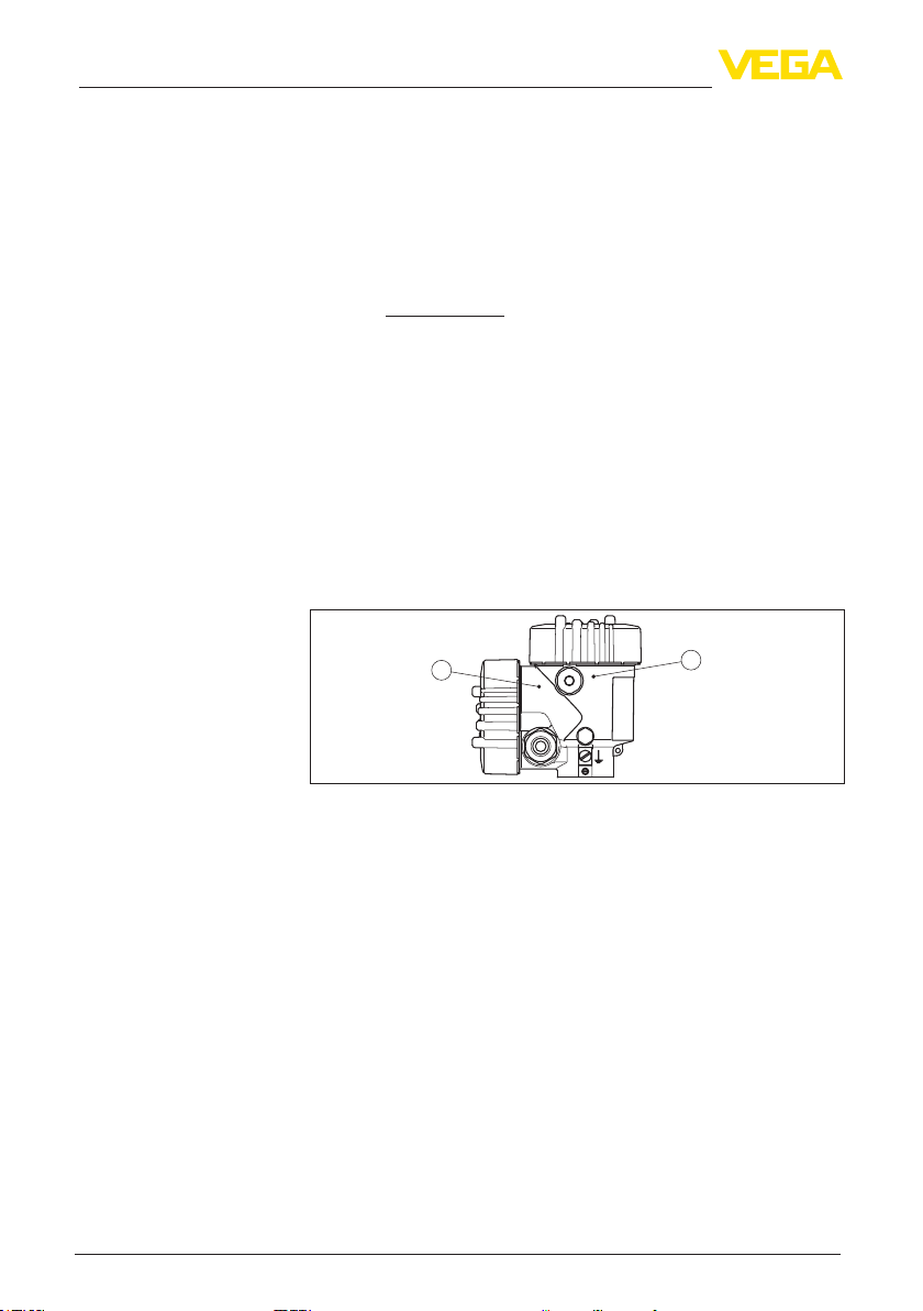
3.1 Conguration.................................................................................................................... 7
3.2 Principle of operation........................................................................................................ 8
3.3 Packaging, transport and storage................................................................................... 10
3.4 Accessories.................................................................................................................... 11
4 Mounting................................................................................................................................. 12
4.1 General instructions ....................................................................................................... 12
4.2 Ventilation and pressure compensation.......................................................................... 14
4.3 Level measurement........................................................................................................ 15
4.4 External housing ............................................................................................................ 15
5 Connecting to power supply and bus system .................................................................... 16
5.1 Preparing the connection ............................................................................................... 16
5.2 Connecting..................................................................................................................... 17
5.3 Wiring plan ..................................................................................................................... 19
5.4 External housing ............................................................................................................ 20
5.5 Switch-on phase............................................................................................................. 22
6 Set up the sensor with the display and adjustment module............................................. 23
6.1 Insert display and adjustment module............................................................................ 23
6.2 Adjustment system......................................................................................................... 24
6.3 Measured value indication.............................................................................................. 25
6.4 Parameter adjustment - Quick setup .............................................................................. 26
6.5 Parameter adjustment - Extended adjustment................................................................ 26
6.6 Menu overview ............................................................................................................... 36
6.7 Save parameter adjustment data.................................................................................... 37
7 Setting up sensor and Modbus interface with PACTware.................................................. 38
7.1 Connect the PC.............................................................................................................. 38
7.2 Parameterization ............................................................................................................ 39
7.3 Set instrument address .................................................................................................. 40
7.4 Save parameter adjustment data.................................................................................... 41
8 Diagnosis, asset management and service ........................................................................ 42
8.1 Maintenance .................................................................................................................. 42
8.2 Diagnosis memory ......................................................................................................... 42

3
Contents
VEGABAR 87 • Modbus and Levelmaster protocol
46297-EN-220624
8.3 Asset Management function........................................................................................... 43
8.4 Rectify faults................................................................................................................... 45
8.5 Exchange process module on version IP68 (25 bar) ...................................................... 46
8.6 Exchanging the electronics module................................................................................ 47
8.7 Software update ............................................................................................................. 47
8.8 How to proceed if a repair is necessary.......................................................................... 48
9 Dismount................................................................................................................................. 49
9.1 Dismounting steps.......................................................................................................... 49
9.2 Disposal ......................................................................................................................... 49
10 Supplement ............................................................................................................................ 50
10.1 Technical data ................................................................................................................ 50
10.2 Device communication Modbus ..................................................................................... 58
10.3 Modbus register ............................................................................................................. 59
10.4 Modbus RTU commands ............................................................................................... 61
10.5 Levelmaster commands ................................................................................................. 64
10.6 CongurationoftypicalModbushosts ........................................................................... 67
10.7 Calculation of the total deviation..................................................................................... 67
10.8 Practical example........................................................................................................... 68
10.9 Dimensions .................................................................................................................... 70
10.10 Industrial property rights................................................................................................. 78
10.11 Trademark ...................................................................................................................... 78
Safety instructions for Ex areas:
TakenoteoftheExspecicsafetyinstructionsforExapplications.
These instructions are attached as documents to each instrument
with Ex approval and are part of the operating instructions.
Editing status: 2022-04-20

4
1 About this document
VEGABAR 87 • Modbus and Levelmaster protocol
46297-EN-220624
1 About this document
1.1 Function
This instruction provides all the information you need for mounting,
connection and setup as well as important instructions for mainte-
nance,faultrectication,theexchangeofpartsandthesafetyofthe
user. Please read this information before putting the instrument into
operation and keep this manual accessible in the immediate vicinity
of the device.
1.2 Target group
This operating instructions manual is directed to trained personnel.
Thecontentsofthismanualmustbemadeavailabletothequalied
personnel and implemented.
1.3 Symbols used
Document ID
This symbol on the front page of this instruction refers to the Docu-
ment ID. By entering the Document ID on www.vega.com you will
reach the document download.
Information, note, tip: This symbol indicates helpful additional infor-
mation and tips for successful work.
Note: This symbol indicates notes to prevent failures, malfunctions,
damage to devices or plants.
Caution: Non-observance of the information marked with this symbol
may result in personal injury.
Warning: Non-observance of the information marked with this symbol
may result in serious or fatal personal injury.
Danger: Non-observance of the information marked with this symbol
results in serious or fatal personal injury.
Ex applications
This symbol indicates special instructions for Ex applications.
• List
The dot set in front indicates a list with no implied sequence.
1 Sequence of actions
Numbers set in front indicate successive steps in a procedure.
Disposal
This symbol indicates special instructions for disposal.

5
2 For your safety
VEGABAR 87 • Modbus and Levelmaster protocol
46297-EN-220624
2 For your safety
2.1 Authorised personnel
All operations described in this documentation must be carried out
onlybytrained,qualiedpersonnelauthorisedbytheplantoperator.
During work on and with the device, the required personal protective
equipment must always be worn.
2.2 Appropriate use
Model VEGABAR 87 is a pressure transmitter for level and gauge
measurement.
Youcannddetailedinformationabouttheareaofapplicationin
chapter " Product description".
Operational reliability is ensured only if the instrument is properly
usedaccordingtothespecicationsintheoperatinginstructions
manual as well as possible supplementary instructions.
2.3 Warning about incorrect use
Inappropriate or incorrect use of this product can give rise to applica-
tion-specichazards,e.g.vesseloverllthroughincorrectmounting
or adjustment. Damage to property and persons or environmental
contamination can result. Also, the protective characteristics of the
instrument can be impaired.
2.4 General safety instructions
This is a state-of-the-art instrument complying with all prevailing
regulations and directives.The instrument must only be operated in a
technicallyawlessandreliablecondition.Theoperatorisresponsi-
ble for the trouble-free operation of the instrument.When measuring
aggressive or corrosive media that can cause a dangerous situation
if the instrument malfunctions, the operator has to implement suitable
measures to make sure the instrument is functioning properly.
The safety instructions in this operating instructions manual, the na-
tional installation standards as well as the valid safety regulations and
accident prevention rules must be observed by the user.
For safety and warranty reasons, any invasive work on the device
beyond that described in the operating instructions manual may be
carried out only by personnel authorised by the manufacturer. Arbi-
traryconversionsormodicationsareexplicitlyforbidden.Forsafety
reasons,onlytheaccessoryspeciedbythemanufacturermustbe
used.
To avoid any danger, the safety approval markings and safety tips on
the device must also be observed.
2.5 EU conformity
ThedevicefullsthelegalrequirementsoftheapplicableEUdirec-
tives.ByaxingtheCEmarking,weconrmtheconformityofthe
instrument with these directives.

6
2 For your safety
VEGABAR 87 • Modbus and Levelmaster protocol
46297-EN-220624
The EU conformity declaration can be found on our homepage.
2.6 NAMUR recommendations
NAMUR is the automation technology user association in the process
industry in Germany. The published NAMUR recommendations are
acceptedasthestandardineldinstrumentation.
ThedevicefullstherequirementsofthefollowingNAMURrecom-
mendations:
• NE 21 – Electromagnetic compatibility of equipment
• NE53–Compatibilityofelddevicesanddisplay/adjustment
components
• NE107–Self-monitoringanddiagnosisofelddevices
For further information see www.namur.de.
2.7 Installation and operation in the USA and
Canada
This information is only valid for USA and Canada. Hence the follow-
ing text is only available in the English language.
Installations in the US shall comply with the relevant requirements of
theNationalElectricalCode(ANSI/NFPA70).
Installations in Canada shall comply with the relevant requirements of
the Canadian Electrical Code.
2.8 Environmental instructions
Protection of the environment is one of our most important duties.
That is why we have introduced an environment management system
with the goal of continuously improving company environmental pro-
tection.Theenvironmentmanagementsystemiscertiedaccording
to DIN EN ISO 14001.
Pleasehelpusfullthisobligationbyobservingtheenvironmental
instructions in this manual:
• Chapter " Packaging, transport and storage"
• Chapter " Disposal"

7
3 Product description
VEGABAR 87 • Modbus and Levelmaster protocol
46297-EN-220624
3 Product description
3.1 Conguration
The scope of delivery encompasses:
• VEGABAR 87 pressure transmitter
The further scope of delivery encompasses:
• Documentation
– Quick setup guide VEGABAR 87
– Testcerticateforpressuretransmitters
– Instructions for optional instrument features
– Ex-specic"Safety instructions" (with Ex versions)
– Ifnecessary,furthercerticates
Information:
Optional instrument features are also described in this operating
instructions manual.The respective scope of delivery results from the
orderspecication.
This operating instructions manual applies to the following instrument
versions:
• Hardware from 1.0.0
• Software from 1.3.6
Note:
Youcanndthehardwareandsoftwareversionoftheinstrumentas
follows:
• On the type plate of the electronics module
• In the adjustment menu under " Info"
Thetypelabelcontainsthemostimportantdataforidenticationand
use of the instrument:
7
6
4
5
2
3
1
Fig. 1: Layout of the type label (example)
1 Product code
2 Field for approvals
3 Technical data
4 Serial number of the instrument
5 QR code
6 Symbol of the device protection class
7 ID numbers, instrument documentation
Scope of delivery
Scope of this operating
instructions
Type label

8
3 Product description
VEGABAR 87 • Modbus and Levelmaster protocol
46297-EN-220624
The type label contains the serial number of the instrument. With it
youcanndthefollowinginstrumentdataonourhomepage:
• Product code (HTML)
• Delivery date (HTML)
• Order-specicinstrumentfeatures(HTML)
• Operating instructions and quick setup guide at the time of ship-
ment (PDF)
• Testcerticate(PDF)-optional
Move to " www.vega.com"andenterinthesearcheldtheserial
number of your instrument.
Alternatively, you can access the data via your smartphone:
• Download the VEGA Tools app from the " Apple App Store" or the
" Google Play Store"
• Scan the QR-code on the type label of the device or
• Enter the serial number manually in the app
Theinstrumentcontainstwodierentelectronicsinitshousingcham-
bers:
• The Modbus electronics for power supply and communication with
the Modbus-RTU
• The sensor electronics for the actual measuring tasks
2
1
Fig. 2: Position of Modbus and sensor electronics
1 Modbus electronics
2 Sensor electronics
3.2 Principle of operation
The VEGABAR 87 is a pressure transmitter for pressure and level
measurements of liquids with higher temperatures in the chemical,
food processing and pharmaceutical industry.
Measured products are liquids.
Depending on the instrument version and the measurement setup,
the measured products can be also viscous.
The VEGABAR 87 is suitable for the measurement of the following
process variables:
• Level
Serial number - Instru-
ment search
Electronics design
Application area
Measured products
Measured variables

9
3 Product description
VEGABAR 87 • Modbus and Levelmaster protocol
46297-EN-220624
Fig. 3: Level measurement with VEGABAR 87
The process pressure acts on the sensor element via the stainless
steel diaphragm and an internal transmission liquid.The process
pressure causes a resistance change which is converted into a cor-
responding output signal and output as measured value.
The METEC®measuring cell is the measuring unit. It consists of
the ceramic-capacitive CERTEC®measuring cell and a special,
temperature-compensated isolating system.
4
3
2
1
Fig. 4: Conguration of the METEC®measuring cell with VEGABAR 87
1 Process diaphragm
2 Isolating liquid
3 FeNi adapter
4 CERTEC®measuring cell
Measuring system

10
3 Product description
VEGABAR 87 • Modbus and Levelmaster protocol
46297-EN-220624
Temperature sensors in the ceramic diaphragm and the ceramic base
of the CERTEC®measuring cell detect the actual process tempera-
ture.The temperature value is output via:
• The display and adjustment module
• The current output or the additional current output
• The digital signal output
The measuring cell design depends on the selected pressure type.
Relative pressure: the measuring cell is open to the atmosphere.
The ambient pressure is detected in the measuring cell and compen-
sated.Itthushasnoinuenceonthemeasuredvalue.
Absolute pressure: the measuring cell contains vacuum and is
encapsulated. The ambient pressure is not compensated and does
henceinuencethemeasuredvalue.
Relative pressure, climate-compensated: the measuring cell is
evacuated and encapsulated. The ambient pressure is detected
through a reference sensor in the electronics and compensated. It
thushasnoinuenceonthemeasuredvalue.
The measuring system is completely welded and hence sealed
againsttheprocess.Thesealingoftheprocessttingagainstthe
process is carried out by a seal provided on site.
3.3 Packaging, transport and storage
Your instrument was protected by packaging during transport. Its
capacity to handle normal loads during transport is assured by a test
based on ISO 4180.
The packaging consists of environment-friendly, recyclable card-
board. For special versions, PE foam or PE foil is also used. Dispose
of the packaging material via specialised recycling companies.
Transport must be carried out in due consideration of the notes on the
transport packaging. Nonobservance of these instructions can cause
damage to the device.
The delivery must be checked for completeness and possible transit
damage immediately at receipt. Ascertained transit damage or con-
cealed defects must be appropriately dealt with.
Up to the time of installation, the packages must be left closed and
stored according to the orientation and storage markings on the
outside.
Unless otherwise indicated, the packages must be stored only under
the following conditions:
• Not in the open
• Dry and dust free
• Not exposed to corrosive media
• Protected against solar radiation
• Avoiding mechanical shock and vibration
Measuring system tem-
perature
Pressure types
Seal concept
Packaging
Transport
Transport inspection
Storage

11
3 Product description
VEGABAR 87 • Modbus and Levelmaster protocol
46297-EN-220624
• Storage and transport temperature see chapter " Supplement -
Technical data - Ambient conditions"
• Relative moisture 20 … 85 %
With instrument weights of more than 18 kg (39.68 lbs) suitable and
approved equipment must be used for lifting and carrying.
3.4 Accessories
The instructions for the listed accessories can be found in the down-
load area on our homepage.
The display and adjustment module is used for measured value indi-
cation, adjustment and diagnosis.
The integrated Bluetooth module (optional) enables wireless adjust-
ment via standard adjustment devices.
The interface adapter VEGACONNECT enables the connection of
communication-capable instruments to the USB interface of a PC.
Secondary sensors of VEGABAR series 80 enable in conjunction with
VEGABAR87anelectronicdierentialpressuremeasurement.
The VEGADIS 81 is an external display and adjustment unit for VEGA
plics®sensors.
The VEGADIS adapter is an accessory part for sensors with double
chamber housings. It enables the connection of VEGADIS 81 to the
sensor housing via an M12 x 1 plug.
The protective cover protects the sensor housing against soiling and
intense heat from solar radiation.
Screwedangesareavailableindierentversionsaccordingtothe
following standards: DIN 2501, EN 1092-1, BS 10, ASME B 16.5,
JIS B 2210-1984, GOST 12821-80.
Welded sockets are used to connect the devices to the process.
Threaded and hygienic adapters enable simple adaptation of devices
withstandardthreadedttingstoprocess-sidehygieneconnections.
Storage and transport
temperature
Lifting and carrying
Display and adjustment
module
VEGACONNECT
Secondary sensors
VEGADIS 81
VEGADIS adapter
Protective cover
Flanges
Welded socket, threaded
and hygienic adapter

12
4 Mounting
VEGABAR 87 • Modbus and Levelmaster protocol
46297-EN-220624
4 Mounting
4.1 General instructions
Note:
For safety reasons, the instrument must only be operated within the
permissibleprocessconditions.Youcannddetailedinformationon
the process conditions in chapter " Technical data" of the operating
instructions or on the type label.
Hence make sure before mounting that all parts of the instrument ex-
posed to the process are suitable for the existing process conditions.
These are mainly:
• Active measuring component
• Processtting
• Process seal
Process conditions in particular are:
• Process pressure
• Process temperature
• Chemical properties of the medium
• Abrasionandmechanicalinuences
Protect your instrument against moisture ingress through the following
measures:
• Use a suitable connection cable (see chapter " Connecting to
power supply")
• Tighten the cable gland or plug connector
• Lead the connection cable downward in front of the cable entry or
plug connector
This applies mainly to outdoor installations, in areas where high
humidity is expected (e.g. through cleaning processes) and on cooled
or heated vessels.
Note:
Make sure that during installation or maintenance no moisture or dirt
can get inside the instrument.
To maintain the housing protection, make sure that the housing lid is
closed during operation and locked, if necessary.
Deviceswiththreadedttingarescrewedintotheprocessttingwith
a suitable wrench via the hexagon.
See chapter " Dimensions" for wrench size.
Warning:
The housing or the electrical connection may not be used for screw-
ing in! Depending on the device version, tightening can cause dam-
age, e. g. to the rotation mechanism of the housing.
Avoid damages on the device by lateral forces, for example by vibra-
tions.Itisthusrecommendedtoxthedeviceswithprocesstting
Process conditions
Protection against mois-
ture
Screwing in
Vibrations

13
4 Mounting
VEGABAR 87 • Modbus and Levelmaster protocol
46297-EN-220624
thread G½ of plastic at the installation site via a suitable measuring
instrument holder.
If there is strong vibration at the mounting location, the instrument
version with external housing should be used. See chapter " External
housing".
Thepermissibleprocesspressurerangeisspeciedonthetypelabel
with "MWP" (Maximum Working Pressure), see chapter " Congura-
tion".This applies even if a measuring cell with a measuring range
(order-related) higher than the permissible pressure range of the
processttingisinstalled.
Inaddition,atemperaturederatingoftheprocesstting,e.g.with
anges,canlimitthepermissibleprocesspressurerangeaccording
to the respective standard.
The permissible process pressure range is stated on the type label.
The instrument should only be operated with these pressures if the
mountingaccessoryusedalsofullsthesevalues.Thisshouldbeen-
suredbysuitableanges,weldedsockets,tensionringswithClamp
connections, sealings, etc.
Higher process temperatures often mean also higher ambient
temperatures. Make sure that the upper temperature limits stated in
chapter " Technical data" for the environment of the electronics hous-
ing and connection cable are not exceeded.
2
1
Fig. 5: Temperature ranges
1 Process temperature
2 Ambient temperature
Depending on the transmitter, the VEGABAR 87 is supplied with a
protective cap or a transport and mounting protection.
Permissible process
pressure (MWP) - Device
Permissible process
pressure (MWP) - Mount-
ing accessory
Temperature limits
Transport and mounting
protection

14
4 Mounting
VEGABAR 87 • Modbus and Levelmaster protocol
46297-EN-220624
1
2
Fig. 6: VEGABAR 87, transport and mounting protection
1 Transmitter
2 Transport and mounting protection
Remove this protection after mounting and before setting up the
instrument.
In case of slightly contaminated measured media, the transport and
mounting protection can remain on the instrument as an impact pro-
tection during operation.
4.2 Ventilation and pressure compensation
Thelterelementintheelectronicshousinghasthefollowingfunc-
tions:
• Ventilation of the electronics housing
• Atmospheric pressure compensation (with relative pressure meas-
uring ranges)
Caution:
Thelterelementcausesatime-delayedpressurecompensation.
Whenquicklyopening/closingthehousingcover,themeasuredvalue
can change for approx. 5 s by up to 15 mbar.
Foraneectiveventilation,thelterelementmustbealwaysfreefrom
buildup. In case of horizontal mounting, turn the housing so that the
lterelementpointsdownwardaftertheinstrumentisinstalled.This
provides better protection against buildup.
Caution:
Donotuseahigh-pressurecleaner.Thelterelementcouldbedam-
aged, which would allow moisture into the housing.
Thefollowingparagraphsdescribehowthelterelementisarranged
inthedierentinstrumentversions.
Filter element - Function

15
4 Mounting
VEGABAR 87 • Modbus and Levelmaster protocol
46297-EN-220624
33
2
1
Fig. 7: Position of the lter element
1 Plastic double chamber housing
2 Aluminium, stainless steel (precision casting) double chamber
3 Filter element
4.3 Level measurement
Keep the following in mind when setting up the measuring system:
• Donotmounttheinstrumentclosetothellingstreamoremptying
area
• Mount the instrument so that it is protected against pressure
shocks from the stirrer
4.4 External housing
1
2
3
4
Fig. 8: Arrangement measurement loop, external housing
1 Sensor
2 Connection cable sensor, external housing
3 External housing
4 Signal cable
Filter element - Position
Measurement setup
Conguration

16
5 Connecting to power supply and bus system
VEGABAR 87 • Modbus and Levelmaster protocol
46297-EN-220624
5 Connecting to power supply and bus
system
5.1 Preparing the connection
Always keep in mind the following safety instructions:
• Carryoutelectricalconnectionbytrained,qualiedpersonnel
authorised by the plant operator
• If overvoltage surges are expected, overvoltage arresters should
be installed
Warning:
Only connect or disconnect in de-energized state.
The operating voltage and the digital bus signal are routed via sepa-
rate two-wire connection cables.
Thedataforpowersupplyarespeciedinchapter"Technical data".
Note:
Power the instrument via an energy-limited circuit (power max. 100 W)
acc. to IEC 61010-1, e.g.
• Class 2 power supply unit (acc. to UL1310)
• SELV power supply unit (safety extra-low voltage) with suitable
internal or external limitation of the output current
The instrument is connected with standard two-wire, twisted cable
suitable for RS 485. If electromagnetic interference is expected which
is above the test values of EN 61326 for industrial areas, shielded
cable should be used.
Use cable with round cross section for instruments with housing and
cable gland. Use a cable gland suitable for the cable diameter to
ensurethesealeectofthecablegland(IPprotectionrating).
Make sure that the entire installation is carried out according to the
Fieldbusspecication.Inparticular,makesurethatthebusistermi-
nated with suitable terminating resistors.
Make sure that the cable screen and grounding are carried out ac-
cordingtoFieldbusspecication.Werecommendtoconnectthe
cable screening to ground potential on both ends.
In systems with potential equalisation, connect the cable screening
directly to ground potential at the power supply unit and the sensor.
The cable screening in the sensor must be connected directly to the
internal ground terminal.The ground terminal outside on the housing
must be connected to the potential equalisation (low impedance).
Metric threads:
In the case of instrument housings with metric thread, the cable
glands are screwed in at the factory. They are sealed with plastic
plugs as transport protection.
Safety instructions
Voltage supply
Connection cable
Cable screening and
grounding
Cable glands

17
5 Connecting to power supply and bus system
VEGABAR 87 • Modbus and Levelmaster protocol
46297-EN-220624
Note:
You have to remove these plugs before electrical connection.
NPT thread:
In the case of instrument housings with self-sealing NPT threads, it is
not possible to have the cable entries screwed in at the factory. The
free openings for the cable glands are therefore covered with red dust
protection caps as transport protection.
Note:
Prior to setup you have to replace these protective caps with ap-
proved cable glands or close the openings with suitable blind plugs.
On plastic housings, the NPT cable gland or the Conduit steel tube
must be screwed into the threaded insert without grease.
Max. torque for all housings, see chapter " Technical data".
5.2 Connecting
The voltage supply and signal output are connected via the spring-
loaded terminals in the housing.
Connection to the display and adjustment module or to the interface
adapter is carried out via contact pins in the housing.
Information:
The terminal block is pluggable and can be removed from the
electronics.To do this, lift the terminal block with a small screwdriver
and pull it out. When reinserting the terminal block, you should hear it
snap in.
Proceed as follows:
1. Unscrew the housing lid
2. Loosen compression nut of the cable gland and remove blind
plug
3. Remove approx. 10 cm (4 in) of the cable mantle (signal output),
strip approx. 1 cm (0.4 in) insulation from the ends of the indi-
vidual wires
4. Insert the cable into the sensor through the cable entry
Connection technology
Connection procedure

18
5 Connecting to power supply and bus system
VEGABAR 87 • Modbus and Levelmaster protocol
46297-EN-220624
Fig. 9: Connection steps 5 and 6
5. Insert the wire ends into the terminals according to the wiring plan
Information:
Solidcoresaswellasexiblecoreswithwireendsleevesareinsert-
eddirectlyintotheterminalopenings.Incaseofexiblecoreswithout
end sleeves, press the terminal from above with a small screwdriver,
the terminal opening is then free.When the screwdriver is released,
the terminal closes again.
6. Check the hold of the wires in the terminals by lightly pulling on
them
7. Connect the cable screening to the internal ground terminal, con-
nect the outer ground terminal to potential equalisation in case of
power supply via low voltage
8. Connect the lead cable for voltage supply in the same way ac-
cording to the wiring plan, in addition connect the ground conduc-
tor to the inner ground terminal when powered with mains voltage.
9. Tighten the compression nut of the cable entry gland. The seal
ring must completely encircle the cable
10. Screw the housing lid back on
Theelectricalconnectionisnished.
Information:
The terminal blocks are pluggable and can be removed from the
housing insert. To do this, lift the terminal block with a small screwdriv-
er and pull it out. When inserting the terminal block again, you should
hear it snap in.

19
5 Connecting to power supply and bus system
VEGABAR 87 • Modbus and Levelmaster protocol
46297-EN-220624
5.3 Wiring plan
2
1
Fig. 10: Position of connection compartment (Modbus electronics) and electron-
ics compartment (sensor electronics)
1 Connection compartment
2 Electronics compartment
5678
4...20mA
2
12
+
( ) (-)
11
Fig. 11: Electronics compartment - double chamber housing
1 Internal connection to the connection compartment
2 For display and adjustment module or interface adapter
+
+
power supply
MODBUS
D0
D1
IS GND
USB
1
2
4 3
1345
2off on
( )
(
)
(-)
(-)
Fig. 12: Connection compartment
1 USB interface
2 Slide switch for integrated termination resistor (120 Ω)
3 Modbus signal
4 Voltage supply
Terminal Function Polarity
1 Voltage supply +
Overview
Electronics compartment
Connection compartment

20
5 Connecting to power supply and bus system
VEGABAR 87 • Modbus and Levelmaster protocol
46297-EN-220624
Terminal Function Polarity
2 Voltage supply -
3 Modbus signal D0 +
4 Modbus signal D1 -
5 Function ground when installing ac-
cording to CSA (Canadian Standards
Association)
5.4 External housing
1234
6
34
12
5
Fig. 13: Connection of the sensor in the housing base
1 Yellow
2 White
3 Red
4 Black
5 Shielding
6 Breather capillaries
Terminal compartment,
housing socket
Other manuals for VEGABAR 87
7
Table of contents
Other Vega Transmitter manuals

Vega
Vega VEGABAR 17 User manual

Vega
Vega VEGADIF 65 User manual

Vega
Vega VEGABAR 82 User manual

Vega
Vega VEGABAR 82 User manual

Vega
Vega VEGADIF 85 User manual

Vega
Vega VEGADIF 85 User manual

Vega
Vega VEGABAR 81 User manual

Vega
Vega VEGABAR 87 User manual

Vega
Vega VEGAWELL 52 User manual

Vega
Vega VEGABAR 83 User manual

Vega
Vega VEGABAR 82 User manual

Vega
Vega VEGABAR 82 User manual

Vega
Vega VEGABAR 29 User manual

Vega
Vega VEGABAR 81 User manual

Vega
Vega VEGADIF 85 User manual

Vega
Vega VEGABAR 83 User manual

Vega
Vega VEGABAR 54 User manual

Vega
Vega VEGABAR 52 User manual

Vega
Vega VEGABAR 86 User manual

Vega
Vega VEGABAR 86 User manual