Cervis Warrior CB-9X User manual

2019 Cervis, Inc.
CB-9X Console Box
Transmitters
Manual U103.1.0
™

Warrior CB-9X Console Box Transmitters
This document is the property of Cervis, Inc. and cannot be copied, modified, e-mailed, or reproduced without the express
prior written consent of Cervis, Inc.
Cervis, Inc. reserves the right to change this manual or edit, delete, or modify any information without prior notification.
FCC Statements
15.19 –Two Part Warning
This device complies with Part 15 of the FCC rules. Operation is subject to the following two conditions:
(1) This device may not cause harmful interference and
(2) This device must accept any interference received, including interference that may cause undesired operation.
15.21 –Unauthorized Modification
NOTICE: The manufacturer is not responsible for any unauthorized modifications to this equipment made by the user. Such modifications could
void the user’s authority to operate the equipment.
15.105(b) –Note:
This equipment has been tested and found to comply with the limits for a Class B digital device, pursuant to Part 15 of the FCC Rules. These
limits are designed to provide reasonable protection against harmful interference in a residential installation. This equipment generates, uses and
can radiate radio frequency energy and, if not installed and used in accordance with the instructions, may cause harmful interference to radio
communications. However, there is no guarantee that interference will not occur in a particular installation. If this equipment does cause harmful
interference to radio or television reception, which can be determined by turning the equipment off and on, the user is encouraged to try to
correct the interference by one or more of the following measures:
Reorient or relocate the receiving antenna.
Increase the separation between the equipment and receiver.
Connect the equipment into an outlet on a circuit different from that to which the receiver is connected.
Industry Canada Statement
This device complies with Canadian RSS-210.
The installer of this radio equipment must ensure that the antenna is located or pointed such that it does not emit RF field in excess of Health Canada limits
for the general population; consult Safety Code 6, obtainable from Health Canada’s website https://www.canada.ca/en/health-
canada/services/environmental-workplace-health/reports-publications/radiation/safety-code-6-health-canada-radiofrequency-exposure-guidelines-
environmental-workplace-health-health-canada.html.
Le présent appareil est conforme à la norme CNR-210 d'Industrie Canada.
L'installateur de cet équipement radio doit s'assurer que l'antenne est située ou orientée de façon à ne pas émettre un champ RF dépassant les limites de
Santé Canada pour la population générale; consulter le Code de sécurité 6, disponible sur le site Web de Santé Canada https://www.canada.ca/en/health-
canada/services/environmental-workplace-health/reports-publications/radiation/safety-code-6-health-canada-radiofrequency-exposure-guidelines-
environmental-workplace-health-health-canada.html.
Industry Canada Statement
This device complies with Industry Canada licence-exempt RSS standard(s). Operation is subject to the following two conditions: (1) this device may not
cause interference, and (2) this device must accept any interference, including interference that may cause undesired operation of the device.
Le présent appareil est conforme aux CNR d'Industrie Canada applicables aux appareils radio exempts de licence. L'exploitation est autorisée aux deux
conditions suivantes : (1) l'appareil ne doit pas produire de brouillage, et (2) l'utilisateur de l'appareil doit accepter tout brouillage radioélectrique subi, même
si le brouillage est susceptible d'en compromettre le fonctionnement.
IC Unlicensed Devices EIRP Statements for Removable Antennas
Part 1: Under Industry Canada regulations, this radio transmitter may only operate using an antenna of a type and maximum (or lesser) gain
approved for the transmitter by Industry Canada. To reduce potential radio interference to other users, the antenna type and its gain should be so
chosen that the equivalent isotropically radiated power (e.i.r.p.) is not more than that necessary for successful communication.
Partie 1 : Conformément à la réglementation d'Industrie Canada, le présent émetteur radio peut fonctionner avec une antenne d'un type et d'un gain maximal
(ou inférieur) approuvé pour l'émetteur par Industrie Canada. Dans le but de réduire les risques de brouillage radioélectrique à l'intention des autres
utilisateurs, il faut choisir le type d'antenne et son gain de sorte que la puissance isotrope rayonnée équivalente (p.i.r.e.) ne dépasse pas l'intensité
nécessaire à l'établissement d'une communication satisfaisante.
Part 2: This radio transmitter (LOBSRF-310) has been approved by Industry Canada to operate with the antenna type listed below with the
maximum permissible gain and required antenna impedance for each antenna type indicated. Antenna types not included in this list, having a
gain greater than the maximum gain indicated for that type, are strictly prohibited for use with this device.
Partie 2 : Cet émetteur radio (LOBSRF-310) a été approuvé par Industrie Canada pour fonctionner avec le type d'antenne indiqué ci-dessous avec le gain
maximal admissible et l'impédance d'antenne requise pour chaque type d'antenne indiqué. Il est strictement interdit d'utiliser avec cet appareil un type
d'antenne ne figurant pas dans cette liste ou ayant un gain supérieur au gain maximum indiqué pour ce type.

2019 Cervis, Inc.
i
Table of Contents
Table of Contents.......................................................................................................................... i
List of Figures ............................................................................................................................... i
List of Tables................................................................................................................................. i
Cervis, Inc. Safety Precautions .................................................................................................. ii
1.0 Warrior CB-9X Transmitter Introduction ........................................................................... 1
1.1 Features............................................................................................................................. 1
1.2 Warrior CB-9X Custom Options...................................................................................... 1
2.0 Warrior CB-9X Console Box Transmitters ........................................................................ 2
2.1 Warrior CB-9X Diagnostic/Status LEDs ......................................................................... 2
2.2 Warrior CB-9X Battery Installation and Replacement................................................... 4
2.3 Neck/Shoulder Harness ................................................................................................... 5
2.3.1 Adjusting the Harness.................................................................................................. 5
2.3.2 Attaching the Harness to the CB-9X ............................................................................ 6
2.4 Turn CB-9X Transmitter On ........................................................................................... 10
2.5 Turn CB-9X Transmitter Off........................................................................................... 11
2.6 Associate CB-9X with the System Receiver ................................................................ 11
2.7 Clearing CB-9X Stored Receiver ID (Factory Reset) ................................................... 14
3.0 Warrior CB-9X Console Box Specifications.................................................................... 16
Appendix A: Exposure to Radio Frequency Energy .............................................................. 17
Appendix B: RF Exposure Considerations ............................................................................. 17
Appendix C: Agency Identification Label Location................................................................ 18
Appendix D: CB-9X Product Family Common Features ........................................................ 19
List of Figures
Figure 1. Warrior CB-9X Wireless Transmitter Examples..........................................................2
Figure 2. Warrior Console Box Battery Installation....................................................................4
Figure 3. Turn CB-9X Transmitter On ........................................................................................10
Figure 4. Associate Console Box with Receiver.......................................................................13
Figure 5. Clearing the ID (Factory Reset) ..................................................................................15
Figure 6. Agency Identification Label Locations ......................................................................18
List of Tables
Table 1. Warrior CB-9X Transmitter LEDs...................................................................................2
Table 2. Advanced LED Diagnostics............................................................................................3
Table 3. Warrior CB-9X Console Box Specifications................................................................16
Table 4. CB-9X Product Family Common Features ..................................................................19

Warrior CB-9X Console Box Transmitters
U103.1.0
ii
Cervis, Inc. Safety Precautions
Read and follow all instructions.
Failure to abide by Safety Precautions may cause equipment failure, loss of authority
to operate the equipment, and personal injury.
Use and maintain proper wiring. Follow equipment manufacturer instructions.
Improper, loose, and frayed wiring can cause system failure, equipment damage, and
intermittent operation.
Changes or modifications made to equipment not expressly approved by the
manufacturer will void the warranty.
Equipment owner/operators must abide by all applicable Federal, State, and Local
laws concerning equipment installation and operation. Failure to comply could result
in penalties and could void user authority to operate the equipment.
Make sure that the machinery and surrounding area is clear before operating. Do not
activate the transmitter control system until certain that it is safe to do so.
Turn off the transmitter and remove power from the receiver before attempting any
maintenance. This will prevent accidental operation of the controlled machinery.
Remove power from the receiver by detaching the cable from the receiver or by
removing the source power from the receiver.
Use a damp cloth to keep units clean. Remove mud, concrete, dirt, etc. after use to
prevent obstructing or clogging the buttons, levers, joysticks, wiring, and switches.
Do not allow liquid to enter the transmitter or receiver enclosures. Do not use high-
pressure equipment to clean the transmitter or receiver.
Disconnect the receiver before welding on the machine. Failure to disconnect the
receiver may cause destruction of or damage to the receiver.
Operate and store units only within the specified operation and storage temperatures
defined in this document’s specifications.
Keep high-energy radio frequency (RF) devices away from transmitters. Activating
high-power communication radios—for instance—in close proximity to transmitters
can cause interference and “false” circuit activation.
Do not key two-way radios while using the console box transmitter.
Note: Refer to the custom drawing package included with each shipment for specific details
not included in this manual!

1.0 Warrior CB-9X Transmitter Introduction
The Warrior CB-9X Console Box transmitter primarily controls overhead bridge cranes. It offers
up to seven single-axis bi-directional levers or up to three bi-directional joysticks for crane
motions –as well as toggle switches, pushbuttons, rotary switches, and potentiometer options
for auxiliary functions. Housed in an extremely durable, sealed glass-filled nylon enclosure, the
Warrior CB-9X is ready for duty in harsh environments, including outdoor applications.
Warrior systems operate in the 900MHz FCC Part 15 License-Free radio band. It continuously
monitors its bi-directional radio transmission –the receiver acknowledges each message the
transmitter sends with a message of its own. Transmitter diagnostic LEDs indicate radio signal
integrity, battery life, and A/B select feedback to the operator. You can pair the reliable,
ergonomically designed Warrior CB-9X transmitter with all Cervis Warrior receivers, including
the MU-6E.
1.1 Features
Up to seven single-axis bi-directional levers, or up to three bi-directional joysticks
Stepless or up to 5-step control from stepless levers
Options for toggles, potentiometers, pushbuttons, and rotary switches for auxiliary
functions
900MHz @ 100mW FCC Part 15 license-free operation
Standard four system status/diagnostic LEDs
Operates using two C-cell batteries
An EAO stop button
Key on and off (usually on the right side)
Neck/shoulder harness standard; optional belt mounting available
Optional 8-character LED display
Unsurpassed durability and environmental sealing
1.2 Warrior CB-9X Custom Options
Controls and Switches
Warrior CBs offer a variety of controls and switch types that provide an extensive number of
configuration and control options. These include:
Multiple two- or three-position momentary or maintained toggle switches on the top deck,
and up to three toggles on either side.
A variety of design-dependent pushbuttons, potentiometers, and rotary switches.
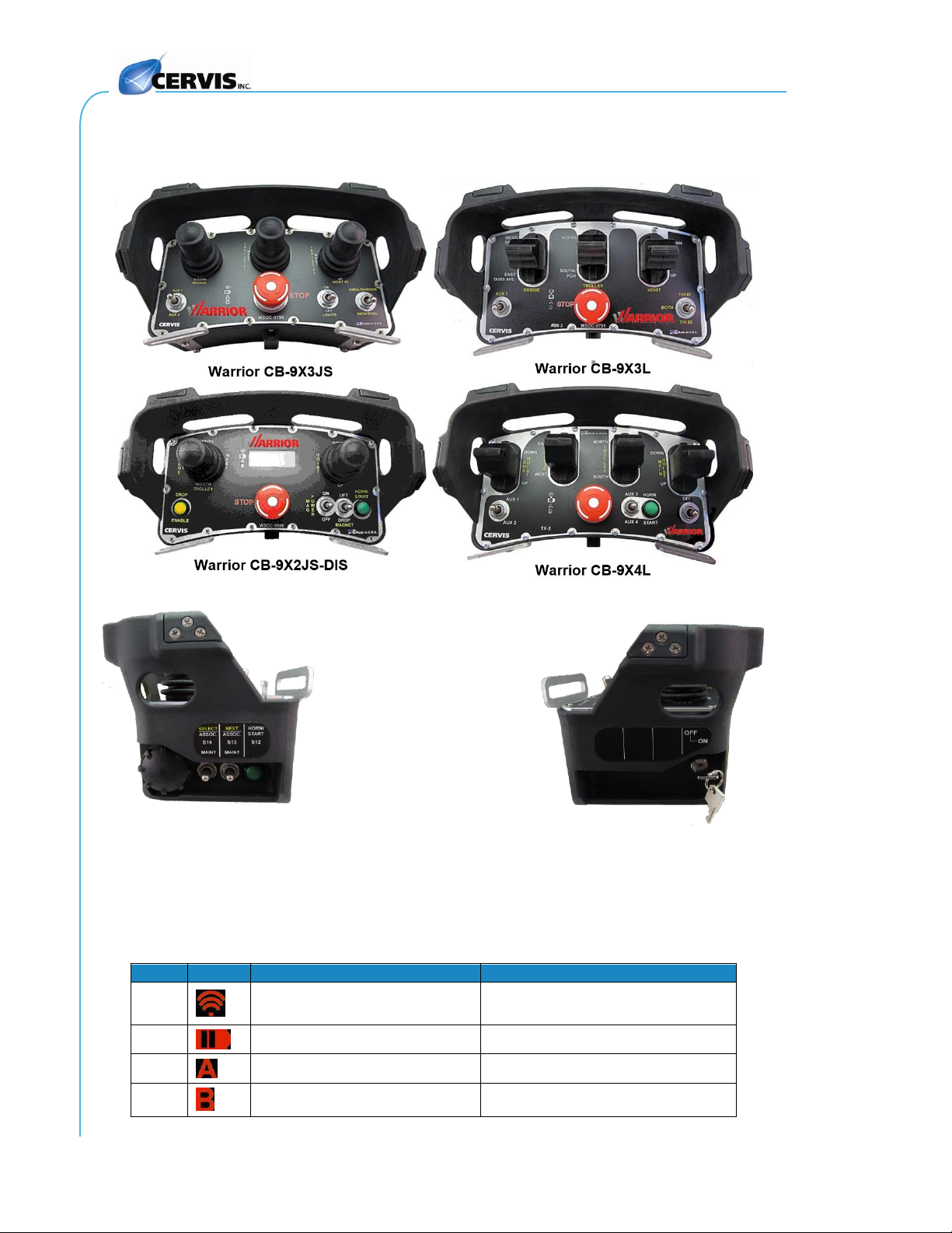
Figure 1 illustrates several examples of Warrior CB-9X console boxes and switch/controls
variations.
Branding/Labeling Option
Cervis, Inc. offers in-house design of attractive custom labels for engineered system CBs
designed to your specifications. Custom labels—made of durable Lexan™ polycarbonate—can
include client logos, specific function text, and specific foreground and background colors.
Warrior CB-9X Console Box Transmitters
U103.1.0
2
2.0 Warrior CB-9X Console Box Transmitters
Figure 1. Warrior CB-9X Wireless Transmitter Examples
2.1 Warrior CB-9X Diagnostic/Status LEDs
Warrior CBs have four red standard diagnostic/status LEDs.
Table 1. Warrior CB-9X Transmitter LEDs
LED
Icon
Function
Action
L1
Transmit (TX) and Receive (RX)
indication
Flashes when message is sent or
received
L2
Battery Status indication
Low battery warning when on (<2.2V)
L3
A Selection
Lights when A selected
L4
B Selection
Lights when B selected
Left Side
S14 S13 S12
Right Side
S18

2019 Cervis, Inc.
3
Table 2. Advanced LED Diagnostics
LEDs
Indication
Diagnostic
RF
RF Solid
Transmitting, looking for receiver.
RF Blinking
Transmitting to and receiving from the mounted receiver.
Bat
RF/A ↔ Bat/B
↔
M-Stop Check: Cycle M-Stop, Blinks back-and-forth.
RF/Bat ↔A/B
↔
Stuck switch: Check switches/proportional not neutral.
RF→Bat→A→B→RF→Bat
Scrolling: Tilt Mode active.
B→A→Bat→RF→B
Scrolling: Signifies Maintenance Mode
Bat
Blinking: Batteries low, replace with fresh batteries soon.
Select
RF/BAT/A/B
Shutting Off: Unit is shutting down:
Inactivity timeout
M-Stop engaged
Keyswitch moved to OFF
Unit wake-up without switch S12

Warrior CB-9X Console Box Transmitters
U103.1.0
4
LEDs
Indication
Diagnostic
Select
Bat
Shutting Off: Batteries below operating level; unit shutting down;
replace batteries with fresh set.
A/B
Shutting Off: Joystick/Lever command reached out-of-bounds.
Condition unsafe, operation turning off.
2.2 Warrior CB-9X Battery Installation and Replacement
The Warrior console box transmitter operates between 2.0VDC to 3.2VDC powered by two 1.5V
type “C” cell batteries (included when shipped). Nominal battery life expectancy is approximately
70 to 100 hours of operation
1
before it becomes necessary to replace the batteries.
Figure 2. Warrior Console Box Battery Installation
Battery Replacement Process
1. Remove the battery cover by unscrewing it in the counter-clockwise direction.
2. Remove the discharged batteries and properly dispose according to local
regulations.
3. Place the two “C” cell batteries in the terminal cavity, observing proper polarity
with the negative side inserted first and each positive battery terminal facing
toward the cap. The +polarity marking is cut in the interior of the cap as
illustrated in Figure 2.
1
At room temperature. Not only does usage affect battery life, but so does operating or storing the battery in too-
high- or too-low ambient temperatures. For instance, the longer batteries are exposed to extreme cold or hot
temperatures, the more likely battery life will be negatively affected. Factors such as the age and initial quality of
a battery also may come into play.
OPEN
Observe proper polarity when
placing batteries into the battery
compartment. Improper battery
placement can cause excessive
heat, battery explosion, injury to the
operator, and damage to the
transmitter.
Two C cell Alkaline Batteries
Battery
Compartment
Gasket
Seal
+
(Positive)

2019 Cervis, Inc.
5
Replace the battery cover by threading it clockwise onto the cavity. You will feel tension as you
tighten the cap. Hand-tighten the cap to compress the compartment O-ring seal embedded in
the cap.
Note: Change batteries soon after the first low battery warning to ensure continued reliable
operation. Cervis, Inc. recommends keeping fresh spare batteries on hand at all times that
the system is in use. The console box transmitter senses when the voltage is at the low
power threshold—approximately 2.2V—at which time, the red battery LED periodically
flashes, warning the operator to change the batteries soon. The warning flashes while the
unit is in use either until you replace the batteries or until the voltage drops below 2.0V, after
which the unit automatically powers down (auto-shutdown). The unit will not power up and
operate until you replace the depleted batteries. Cervis, Inc. recommends replacing them with
two fresh batteries.
2.3 Neck/Shoulder Harness
The 1¾" wide neck/shoulder harness lets you conveniently and comfortably strap the CB-9X
around your neck or shoulder for easy access and operation. Adjustable to lengths up to 60
inches (~1.5m), the harness conforms to most body lengths; and its rugged, heavy-duty
construction and quick-release fasteners keep a single CB-9X securely against your body. Plus,
its polypropylene webbing resists wear, and its bright orange color gives it high visibility against
even the lightest colored garments.
2.3.1 Adjusting the Harness
Before you attach the harness to your CB-9X, adjust the blue strap to the most comfortable
operating length for your individual body type.

Warrior CB-9X Console Box Transmitters
U103.1.0
6
The harness’ left strap features a 6" (152mm) long quick release hook-and-loop Nylon rip cord.
Connect the two parts of the rip cord together, and press down to secure the connection.
2.3.2 Attaching the Harness to the CB-9X
Both ends of the high-visibility orange straps feature a pair of heavy-duty metal button snaps at
the ends.

2019 Cervis, Inc.
7
To attach the harness to your CB-9X, locate either the two T-shaped harness clips on the front
of your CB—one is on the left side; the other is on the right—or the orange bar across the top of
it.
Thread the high visibility orange straps through the harness mounts or bar—snap side up—past
the first two (female) snaps.

Warrior CB-9X Console Box Transmitters
U103.1.0
8
Fold the strap over onto itself, and fasten the female snaps to their male counterparts.
Note: You’ll know the snaps are secured when you hear a clicking sound.

2019 Cervis, Inc.
9
When you have the harness securely together, hang it around your neck—or drape it over your
shoulder—and begin operating your CB-9X.
Warrior CB-9X Console Box Transmitters
U103.1.0
10
2.4 Turn CB-9X Transmitter On
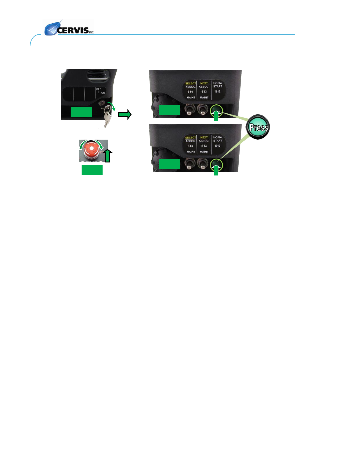
Turn the console box transmitter on and make it ready for use as follows (Figure 3):
Figure 3. Turn CB-9X Transmitter On
1. Move the Keyswitch (S18) 90to the ON position.
2. Press the Horn/Start pushbutton (S12) to wake the transmitter.
3. Release the STOP button by twisting it clockwise until it pops up (spring-loaded).
Note: If the Stop button is already up when beginning, depress it, then raise it.
4. Press the Horn/Start pushbutton (S12) to energize the main line contactor (MLC)
relays.
Step 1
Step 2
Step 3
Step 4
S18
S12
S12
2019 Cervis, Inc.
11
2.5 Turn CB-9X Transmitter Off
Shut down the console box transmitter via any of the following methods:
Push the STOP button down for immediate stop.
Do not activate any switch and wait for the console box Switch Inactivity Timeout to expire
(standard is four minutes).
Turn the keyswitch (S18) to the OFF position.
2.6 Associate CB-9X with the System Receiver
The CB-9X system transmitter must be associated (communications link established) with a
system receiver before the system can be used. The CB-9X stores the target receiver ID
following successful association with a chosen receiver. Systems are associated at Cervis, Inc.
before leaving the factory; but there may be times when it is necessary to associate while in the
field.
Use the associate process described in the following steps to associate a receiver with the CB-
9X transmitter when needed.
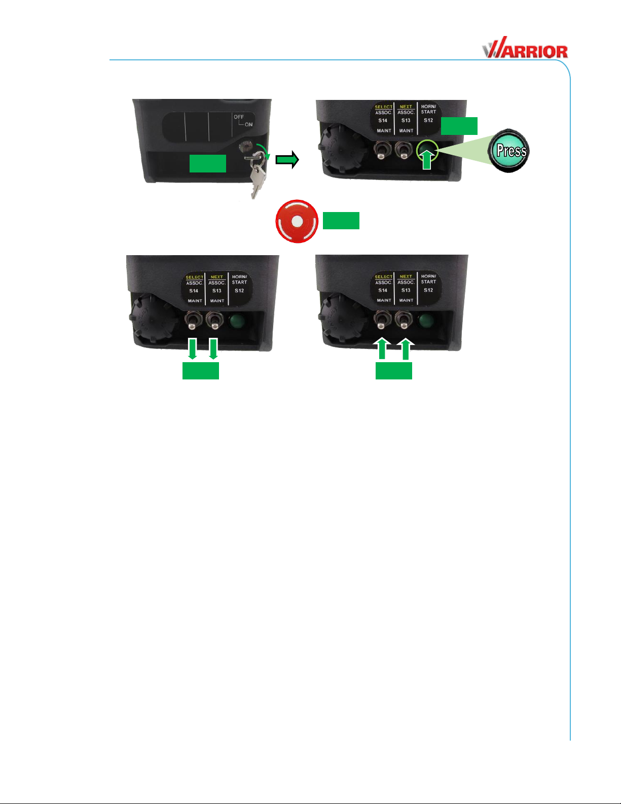
Associate with Receiver (Figure 4)
1. With the Console Box OFF, turn the keyswitch (S18) to the ON position.
2. Press the Horn/Start pushbutton (switch S12) to wake the transmitter.
3. Within 2 seconds after pushing the pushbutton, cycle the STOP Switch
(transition from OFF to ON).
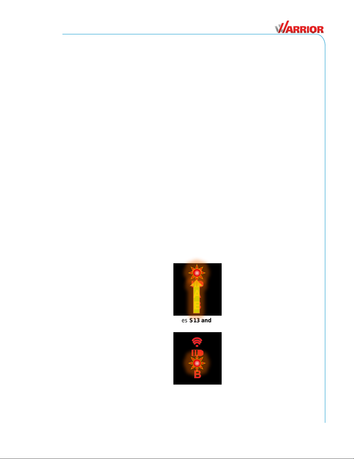
4. The BLED lights for about 1.5 seconds after cycling the STOP Switch. While
this LED is active (ON), enter Maintenance Mode by simultaneously moving
switches S13 and S14 DOWN for approximately one second.
Note: Restart the process if you wait too long to perform this operation.
The LEDs cycle from bottom to top, indicating that the console box is in
Maintenance Mode.
5. Simultaneously lift and hold switches S13 and S14 UP for five seconds to enter
Association Mode. Release both switches when LED Astarts to blink.
6. While in Association Mode, the Band RF LEDs light solid, indicating that the
console box is attempting to locate any available receivers it can Link to.
Warrior CB-9X Console Box Transmitters
U103.1.0
12
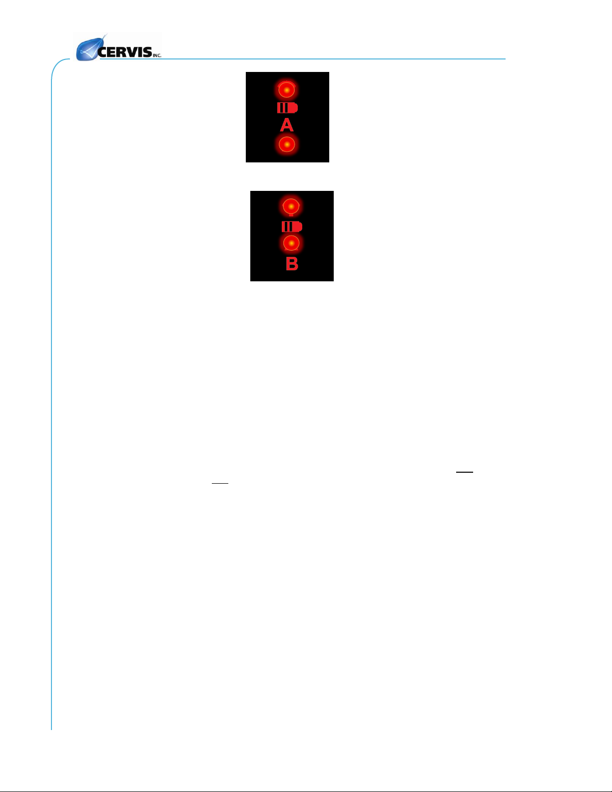
7. The Aand RF LEDs light solid when the console box has completed its search
for available receivers. You can now pick which receiver to link to.
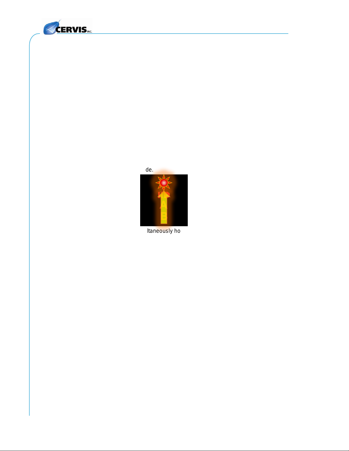
8. A found receiver starts to pulse its Associate Relay. (Wire this relay to an
external indicating device—such as a light or horn—when installing). This alerts
you that the indicated receiver is ready for association. Momentarily lift switch
S13 (NEXT) UP to bypass the indicated receiver. To select that receiver,
momentarily lift switch S14 (SELECT) UP.
9. Press the Horn/Start pushbutton (switch S12)again to pull in the MLC relays.
Once a receiver is selected and the MLC relays are energized, the CB-9X is now linked to that
receiver, and you can run the crane.
Notes:
Each new system’s transmitters are factory associated before being shipped.
If you purchase a spare transmitter, you will need to associate it yourself before it will work
with that system.
Each transmitter must be associated one time. Once associated with a receiver, that
transmitter will work with that receiver until you clear the receiver ID. (See Section 2.7.)
The transmitter works in a first-come/first-serve basis, where only one transmitter unit can
ever be paired to a receiver unit at a time.
2019 Cervis, Inc.
13
Figure 4. Associate Console Box with Receiver
Step 4
S14 S13
Step 5
S14 S13
Step 1
Step 2
Step 3
CYCLE
OFF→ON OR ON→OFF→ON
S12
S18
Warrior CB-9X Console Box Transmitters
U103.1.0
14
2.7 Clearing CB-9X Stored Receiver ID (Factory Reset)
The CB-9X transmitter stores the associated receiver ID. It may become necessary during
instances of severe interference—or perhaps when troubleshooting—to break the established
communications link between the console box transmitter and the system receiver. This is called
“clearing the ID”or “Factory Reset.”Use the following steps to clear the ID.
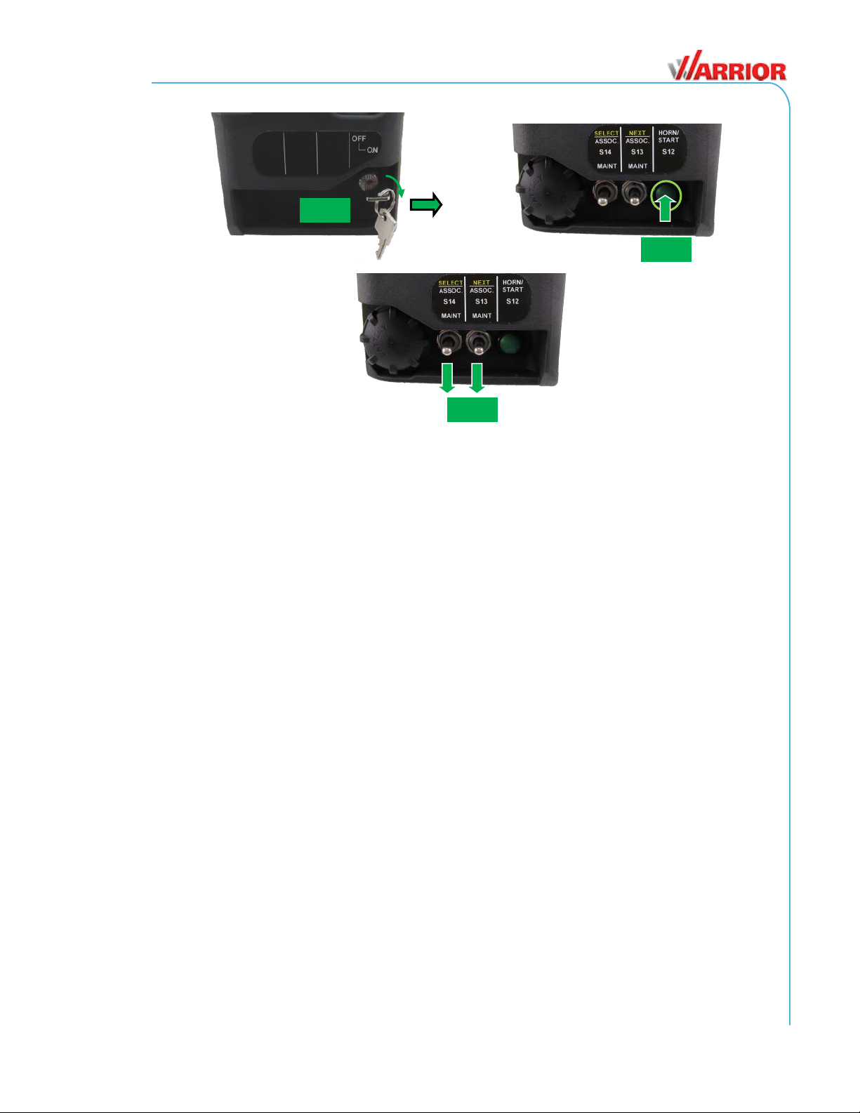
Clear the Stored Receiver ID (Factory Reset)
1. With the console box OFF, turn the keyswitch S18 to the ON position.
2. Momentarily press the Horn/Start pushbutton (S12) to wake the transmitter.
Note: Perform the next step within two seconds. Otherwise, you must restart the
process.
3. Cycle (transition from OFF to ON) the Stop Switch.
4. LED Bwill illuminate for about 1.5 seconds after cycling the stop switch. While
this LED is on, enter Maintenance Mode by simultaneously moving and holding
switches S13 and S14 down until the LEDs cycle from bottom to top, indicating
that the CB is in maintenance mode.
5. While in maintenance mode, simultaneously hold switches S13 and S14 Down.
Press the Stop Switch while holding the switches down.
Notes:
When a transmitter is not associated with a receiver, the transmitter lights all the LEDs and
then powers down shortly after being turned on.
The receiver does not need to be on when clearing an ID from the transmitter.
2019 Cervis, Inc.
15
Figure 5. Clearing the ID (Factory Reset)
Step 3
S14 S13
Step 1
Step 2
S12
S18
Warrior CB-9X Console Box Transmitters
U103.1.0
16
3.0 Warrior CB-9X Console Box Specifications
Table 3. Warrior CB-9X Console Box Specifications
Warrior CB-9X Console Box Specifications
Power
+2.0 to +3.2VDC
Two “C” 1.5V Alkaline Batteries
Radio
Frequency
License
Modulation
Antenna
Inactivity Timeout
904–926MHz @ 100mW
License-Free
Channel Hopping (Direct Sequence Spread Spectrum)
Internal
Standard four minutes (adjustable)
Environment
Operating Temp
-4°F to 131°F (-20°C to 55°C)
Storage Temp
-40°F to 185°F (-20°C to 85°C)
Humidity
0 to 95% Non-Condensing
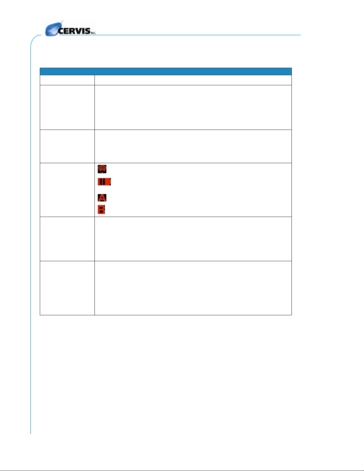
Indicators (4)
TX/RX
Flashes when a message is transmitted or received
Slow Blinks –below 2.2V warning (approaching
discharge; replace batteries)
Lit when A is selected
Lit when B is selected
Enclosure
Dimensions
10.4" x 5.6" x 5.5"
(263.5mm x 141.5mm x 139mm)
Durability
Glass-filled nylon
Aluminum faceplate
Weight
3.95 lbs. (1.8kg)
Function Controls
Joysticks
Two or three single-axis; model dependent
Levers
Up to seven single-axis (Y+, Y-)
Toggles
Two- or three-position maintained or momentary; model
dependent
Pushbuttons
Stop
Two (options available)
Two-position EAO
Other manuals for Warrior CB-9X
1
This manual suits for next models
4
Table of contents
Other Cervis Transmitter manuals


Popular Transmitter manuals by other brands


Speaka Professional
Speaka Professional 2751052 operating instructions

Williams Sound
Williams Sound Transmitter T1-173 Instructions for use and care

YOKOGAWA
YOKOGAWA Dpharp vigilantplant EJA510A user manual

KROHNE
KROHNE OPTISOUND 3010 C Handbook

Emerson
Emerson Rosemount 248 quick start guide

Rain Bird
Rain Bird TBOS-II manual