Ski-Doo Summit x 670 1998 Install guide


-I
1998
Shop Manual
Supplement
SUMMIT x 670
USE IN CONJUNCTION WITH THE SKI-DOO SHOP MANUAL P/N 484 0682 00
®

0
Legal deposit:
National Library of Quebec
4th trimester 1997
National Library of Canada1997
All rights reserved. No parts of this manual may be reproduced in any
form without the prior written permission of Bombardier Inc.
©Bombardier Inc. 1997
Technical Publications
Bombardier Inc.
Valcourt (Quebec) Canada
Printed in Canada
®*Registered trademarks of Bombardier Inc.
TABLE OF CONTENTS

I
SECTION PAGE
SAFETY NOTICE ...................................................................................................................................... III
INTRODUCTION Abbreviations list ......................................................................... IV
Serial numbers ............................................................................ IV
LUBRICATION
AND MAINTENANCE .................................................................................................... *
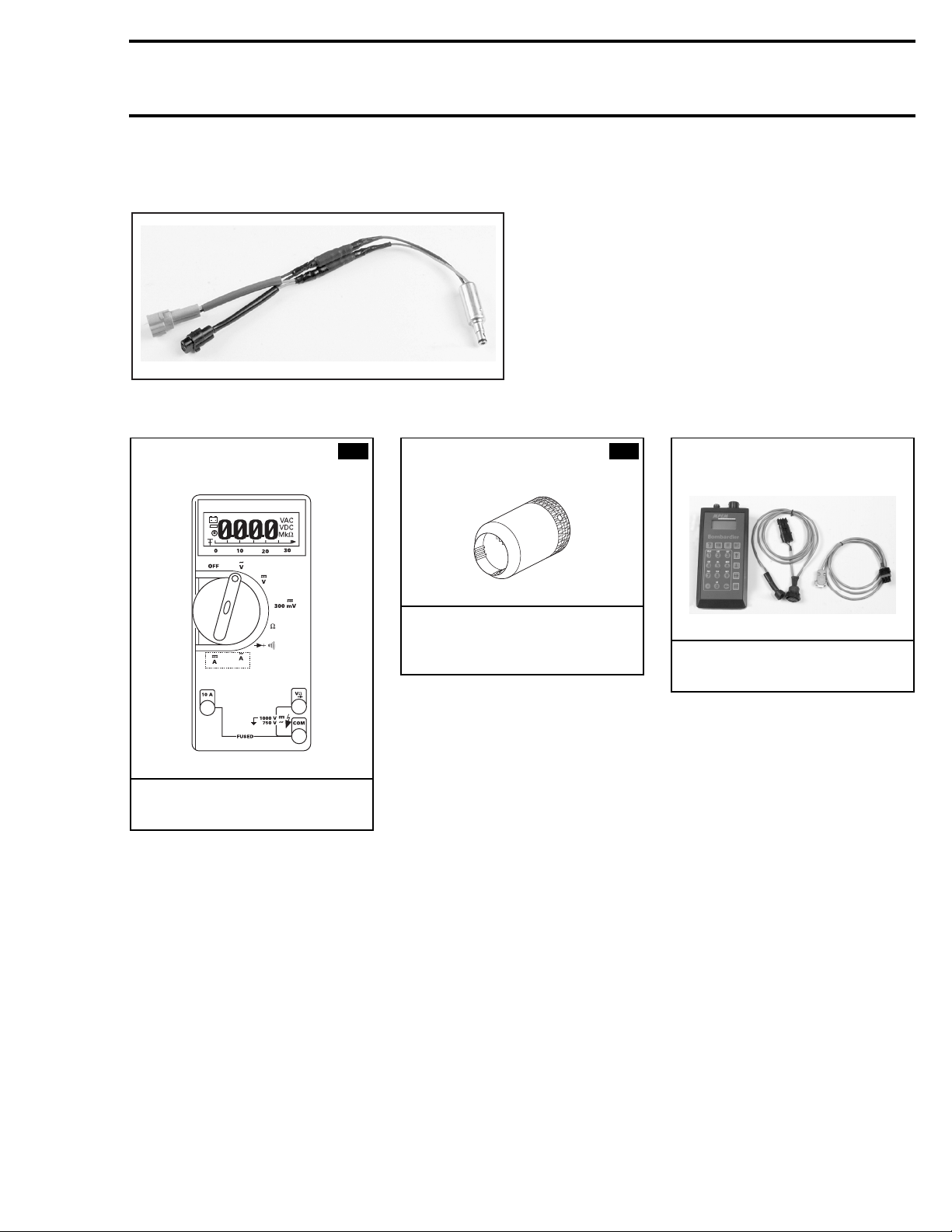
01 TOOLS .................................................................................................... 01-1
02 TROUBLESHOOTING .................................................................................................... 02-1
ENGINE Table of contents......................................................................... *
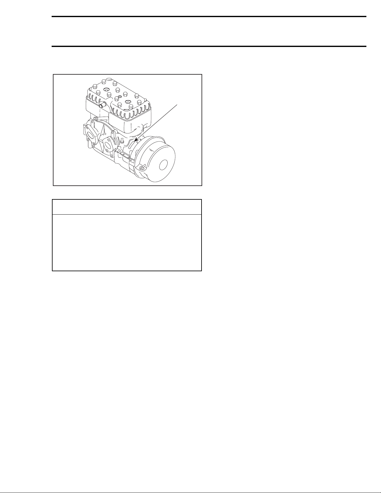
699 Engine ................................................................................. *
Leak test and engine dimension measurement .......................... *
CDI system (220-watt magneto system)..................................... 03-1
Oil injection system..................................................................... 04-1
Liquid cooling system.................................................................. *
Rewind starter............................................................................. *
Carburetor and fuel pump............................................................ *
Fuel tank and throttle cable......................................................... *
TRANSMISSION Table of contents......................................................................... *
Drive belt ..................................................................................... *
Drive pulley.................................................................................. *
Driven pulley................................................................................ *
Pulley distance and alignment..................................................... *
Brake ........................................................................................... *
Gearbox ....................................................................................... *
Drive chain................................................................................... *
03 ELECTRICAL SYSTEM Table of contents......................................................................... *
Wiring diagrams........................................................................... 08-1
Ignition timing.............................................................................. *
Spark plugs.................................................................................. *
220-watt magneto system .......................................................... 03-2
Theory and operation................................................................... 03-2
Testing procedure ....................................................................... 03-2
04 OIL INJECTION SYSTEM Oil injection pump ....................................................................... 04-2
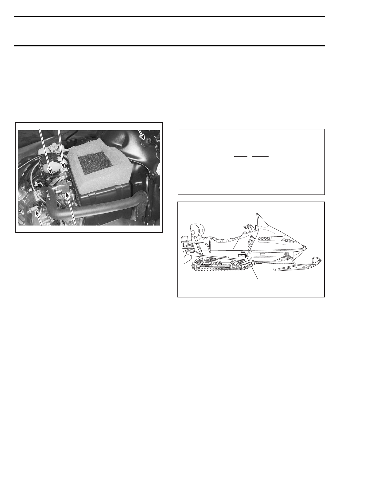
05 DESS SYSTEM Component location .................................................................... 05-1
Theory and operation................................................................... 05-1
Ignition system testing................................................................ 05-3
Lighting system testing............................................................... 05-4
06 DIGITAL PERFORMANCE
MANAGEMENT (DPM)
SYSTEM
Component location .................................................................... 06-2
Theory and operation................................................................... 06-2
Testing procedure ....................................................................... 06-11
Starting procedure....................................................................... 06-12
* Refer to
1998 Shop Manual volume 2
(P/N 484 0682 00)
TABLE OF CONTENTS
$()
VOLUME 2

II
* Refer to
1998 Shop Manual volume 2
(P/N 484 0682 00)
STEERING/
FRONT SUSPENSION Table of contents ........................................................................ *
Steering system.......................................................................... *
Suspension and ski system ........................................................ *
BODY/FRAME Table of contents ........................................................................ *
Body............................................................................................ *
Frame.......................................................................................... *
07 TECHNICAL DATA Engine ......................................................................................... 07-1
Vehicle ........................................................................................ 07-2
Technical data legends................................................................ 07-3
08 WIRING DIAGRAM Wiring diagram legend ................................................................ 08-1
SECTION PAGE
TABLE OF CONTENTS
$()
VOLUME 2

III
SAFETY NOTICE 0
This manual has been prepared as a guide to correctly service and repair the 1998 Ski-Doo Summit x 670.
See model list on next page.
This edition was primarily published to be used by snowmobile mechanics who are already familiar with
all service procedures relating to Bombardier made snowmobiles.
Please note that the instructions will apply only if proper hand tools and special service tools are used.
This
Shop Manual Supplement
uses technical terms which may be slightly different from the ones used
in
Parts Catalog
.
The content depicts parts and/or procedures applicable to the particular product at its time of manufac-
ture. It does not include dealer modifications, whether authorized or not by Bombardier, after manufac-
turing the product.
In addition, the sole purpose of the illustrations throughout the manual, is to assist identification of the
general configuration of the parts. They are not to be interpreted as technical drawings or exact replicas
of the parts.
The use of Bombardier parts is most strongly recommended when considering replacement of any com-
ponent. Dealer and/or distributor assistance should be sought in case of doubt.
The engines and the corresponding components identified in this document should not be utilized on
product(s) other than those mentioned in this document.
Torque wrench tightening specifications must be strictly adhered to. Locking devices (ex.: locking tab,
elastic stop nut, etc.) must be installed or replaced with new ones, when damaged. If the efficiency of a
locking device is impaired, it must be renewed.
This manual emphasizes particular information denoted by the wording and symbols;
NOTE: Indicates supplementary information needed to fully complete an instruction.
Although the mere reading of such information does not eliminate the hazard, your understanding of the
information will promote its correct use. Always use common shop safety practice.
This information relates to the preparation and use of Bombardier snowmobiles and has been utilized
safely and effectively by Bombardier Inc. However, Bombardier Inc. disclaims liability for all damages
and/or injuries resulting from the improper use of the contents. We strongly recommend that any servic-
es be carried out and/or verified by a highly skilled professional mechanic. It is understood that certain
modifications may render use of the vehicle illegal under existing federal, provincial and state regulations.
◆WARNING
Identifies an instruction which, if not followed, could cause serious personal injury including
possibility of death.
-CAUTION
Denotes an instruction which, if not followed, could severely damage vehicle components.
SAFETY NOTICE

IV
INTRODUCTION 0
The 1998 Summit x 670 comprises 2 new sys-
tems compare with Summit 670. The
1998 Shop
Manual Supplement
describes how these sys-
tems operate as well as the procedures to test
them.
1. DESS switch
2. MPEM module including DPM and ignition systems
3. DPM manifold
4. Engine temperature DPM sensor
5. Air temperature DPM sensor
ABBREVIATIONS LIST
CDI Capacitor Discharge Ignition
DESS Digitally Encoded Security System
DPM Digital Performance Management
Hz Hertz (1 cycle per second)
PSI Pound per Square Inch
MAG Magneto ( magneto side)
mbar millibar
MPEM Multi-Purpose Electronic Module
PTO Power Take Off (drive pulley side)
ROM Read Only Memory
RPM Revolutions Per Minute
VDC Volt Direct Current
SERIAL NUMBERS
Each Vehicle has its Particular Vehicle
Serial Number
Serial Number Meaning
TYPICAL
1. Vehicle serial number
The engine also has a serial number.
MODELS MODEL
NUMBER
SUMMIT x 670 (CANADA) ................... 1307
SUMMIT x 670 (U.S.) ........................... 1310
A03A0IA
1
3
25
4
A00A0DA
Model no. Vehicle no.
0000 00000
A06H01A
1
INTRODUCTION

V
Liquid Cooled Engines
1. Engine serial number
-CAUTION
Most components of those vehicles are built
with parts dimensioned in the metric sys-
tem. Most fasteners are metric and must not
be replaced by customary fasteners or vice
versa. Mismatched or incorrect fasteners
could cause damage to the vehicle or possi-
ble personal injury.
A00C1QA
1
INTRODUCTION

Section 01 TOOLS
01-1
TOOLS 0
TYPICAL — ADAPTOR (P/N 529 0338 00)
A00B4HA
Fluke multimeter
(P/N 529 0220 00)
F01B1O4
APPLICATION
All models.
242 Choke nut tool
(P/N 529 0322 00)
A01B554
APPLICATION
All vehicles equipped with a
choke.
782 Programmer
(P/N 529 0355 02)
A01B5B4
APPLICATION
All models equipped with a DESS.

02-1
Section 02 TROUBLESHOOTING
TROUBLESHOOTING 0
DIGITAL PERFORMANCE
MANAGEMENT (DPM)
SYSTEM
If the DPM seems to be defective, unplug both
solenoids while the engine is running. The carbu-
ration is now identical to that of carburetors with-
out a DPM provided, of course, that all pipe
fittings are tight and that solenoids are in good
condition. None must be half-open.

03-1
Section 03 ELECTRICAL SYSTEM
ELECTRICAL SYSTEM 0
4
A03C1ZS
Loctite
242
Loctite 242
Loctite 648
Lithium grease
To main harness
1
2
3
FLAT RATE
PARTS

03-2
Section 03 ELECTRICAL SYSTEM
220-WATT MAGNETO SYSTEM
THEORY AND OPERATION
Charging System
Charging system is identical to Summit 670. Re-
fer to
1998 Shop Manual volume 2
.
The 220-watt magneto no. 1 produces alternating
current.
MPEM Module
(Multi-Purpose Electronic Module)
DPM (Digital Performance Management) system,
DESS (Digital Encoded Security System) and igni-
tion system are integrated into MPEM module
no. 2.
DPM + DESS + Ignition module = MPEM module.
MPEM module operates on alternating current
(AC).
1. Compensation solenoid (3-11 housing)
2. Enrichment solenoid (3-10 housing)
3. Trigger coil (2-02 housing)
4. Ignition coil (3-01 housing)
5. Magneto (3-05 housing)
6. Dess switch (6-03 housing)
7. Warning light, engine shut-off and trigger coil
8. Air temperature DPM sensor (4-09 housing)
9. Cold start switch (4-08 housing)
10. Liquid temperature DPM sensor (3-09 housing)
ENGINE RPM LIMITER
Ignition is cut at 8600 RPM and is re-activated at
8500 RPM.
Ignition
The 220-watt magneto has an ignition generator
coil no. 3. A BLACK/YELLOW wire allows the en-
gine to stop. Grounding this wire will short-circuit
the ignition module.
Trigger coil pulses are sent to the MPEM module
in order to ignite the spark plug at the right time.
TESTING PROCEDURE
Magneto
IGNITION GENERATOR COIL
Resistance Testing
Disconnect 3-05 housing.
Refer to the electrical diagram at the end of this
supplement.
Connect an ohmmeter to the magneto RED and
BLACK/RED wires (3-05A and 3-05B).
HOUSING 3-05 DISCONNECTED
The resistance must be as indicated in the follow-
ing table.
Insulation Test
Disconnect 2-01 housing.
Connect an ohmmeter probe to ground and the
other probe to each of the YELLOW wires.
There must be no continuity.
A03E1WA
10
7
6
5
4
3
2
1
9
8
WIRES RESISTANCE VALUES
Ω
RED and BLACK/RED 10,0 - 15,0
A03E1XA

04-1
Section 04 OIL INJECTION SYSTEM
OIL INJECTION SYSTEM 0
A03C2NS
Loctite 242
Molykote 111
Loctite 242
1
FLAT RATE
PARTS

04-2
Section 04 OIL INJECTION SYSTEM
OIL INJECTION PUMP
Oil injection pump no. 1 is located above carbure-
tors. Maintenance, adjustment and inspection re-
main the same has Summit 670.
Refer to section OIL INJECTION PUMP 04-06 of
1998 Shop Manual vol. 2.
$()
VOLUME 2

05-1
Section 05 DESS SYSTEM
DESS SYSTEM (DIGITALLY ENCODED
SECURITY SYSTEM) 0
COMPONENT LOCATION
1. Safety lanyard switch and cap
2. MPEM
THEORY AND OPERATION
This system is a deterrent against theft. Factory
programmed, the tether cord provided with the
snowmobile is the only one that allows engine to
turn more than 3000 RPM. If a wrong tether cord
is installed the engine can not reach engagement
speed required to move vehicle.
The snowmobile micro-processor (MPEM) can be
programmed to allow the use up to 8 tether cords.
After engine is started DESS indicator light blink-
ing indicates bad connection or wrong tether
cord. Refer to
DESS Indicator Light
on the next
page.
Multi-Purpose Electronic Module
(MPEM)
NOTE: The module must be programmed in order
to accept a tether cord.
This module cuts off the ignition at 3000 RPM in
antitheft mode (wrong tether cord) or in case of a
bad connection.
The module activates the indicator light (depend-
ing on the antitheft mode).
MPEM
1.Compensation solenoid (3-11 housing)
2.Enrichment solenoid (3-10 housing)
3.Trigger coil (2-02 housing)
4.Ignition coil (3-01 housing)
5.Magneto (3-05 housing)
6.DESS switch (6-03 housing)
7.Warning light, engine shut-off and trigger coil (10-01 housing)
8.Air temperature DPM sensor (4-09 housing)
9.Cold start switch (4-08 housing)
10.Liquid temperature DPM sensor (3-09 housing)
DESS Indicator Light
1. DESS indicator light
A03A0IB
1
2
DESS LIGHT CAUSE REMEDY
Blinking
rapidly Wrong tether
cord
Use tether cord
programmed for
snowmobile
Blinking
slowly Bad
connection Clean tether cord
Not blinking Everything
OK Snowmobile can
be driven normally
A03E1WA
10
7
6
5
4
3
2
1
9
8
A03E1YA
1

05-2
Section 05 DESS SYSTEM
DESS Switch
Check using a multimeter by connecting probes to
BLACK/GREEN and BLACK/WHITE wires. The
multimeter should indicate a closed circuit (0.L MΩ)
in operating position and a open circuit (0 Ω) in off
position.
TYPICAL — HARNESS REMOVED FOR CLARITY
1. Housing disconnected
2. DESS cap in place
TYPICAL — HARNESS REMOVED FOR CLARITY
1. Housing disconnected
2. DESS cap remove
TYPICAL — IN-VEHICLE TESTING
If readings do not correspond to the above men-
tioned indications, replace switch.
Trigger Coil
Resistance Testing
1. Connect probes to WHITE/YELLOW and BLUE/
YELLOW wires from trigger coil 2-02 housing.
2. Activate the manual starter and check values in-
dicated by the multimeter.
3. Repeat operation 3 times.
Compare readings with those appearing in the IG-
NITION SYSTEM TESTING table.
A30E0MA
1 2
A30E0NA
2
1
A30E0OA

05-3
Section 05 DESS SYSTEM
IGNITION SYSTEM TESTING (Summit x 670)
PART TEST TO BE
PERFORMED WIRE
COLOR
MULTIMETER
PROBE
CONNECTION
RESISTANCE ΩVOLTAGE V
NOTE
VALUE
(Ohms) MULTIMETER
SCALE Value
(Volts) MULTIMETER
SCALE
Stop switch Running
insulation BK and
BK/YL
3-05C-F
and
10-01A-M 0.L 00.0 MΩ——
No stop switch must be
operational.
Continuity in
stop position BK and
BK/YL
3-05C-F
and
10-01A-M 00.0 - 00.5 00.0 Ω——
At least one stop switch must be
operational.
Insulation in
stop position BK/GN
BK/WH 10-02B-M
10-02C-M 0.L 00.0 MΩ——
Tether cord cap must be
removed
Continuity in
running
position
BK/GN
BK/WH 10-02B-M
10-02C-M 00.0 - 00.5 00.0 Ω——
Tether cord cap must be
removed
Ignition
generator
coil Power RD
BK/RD
3-05A-F
and
3-05B-F 10.0 - 15.0 00.0 Ω10.0 - 13.5 00.0VAC
Coil insulation BK
RD
3-05C-F
and
3-05A-F 0.L 00.0 Ω——
Ground
continuity BK and
engine
3-05C-F
and
engine 00.0 - 00.5 00.0 Ω——
The term “engine” refers to the
engine metal parts connected to
the magneto housing.
Ignition
module Output voltage BK and
WH/BL
3-01-2-F
and
3-01-1-F — — 4.5 - 8.0 00.0VAC
No stop switch must be
operational and tether cord cap
must be in place.
High voltage
coil Primary
winding
resistance
BK and
WH/BL
3-01-2-M
and
3-01-1-M 0.00 - 00.9 00.0 Ω——
Secondary
winding
resistance
(sparkplug cap
included)
Plug
caps
Plug cap
Into
spark plug
caps
19.5 K -
26.5 K 00.0 KΩ-CAUTION
Do not measure high voltage coil output voltage.
Secondary
winding
resistance
BK
BK
On
spark plug
wires
11.5 K -
14.5 K 00.0 KΩ-CAUTION
Do not measure high voltage coil output voltage.
Secondary
winding
voltage
BK
Engine
On spark
plug wire
and engine — — 0.1 - 1.4 0.00VAC The measurement must be taken
on the spark plug wire (without
the spark plug).
Insulation Cap and
BK In cap and
3-01-1-M 0.L 00.0 Ω—— —
Spark plug
cap Cap resistance — Spark plug
side and
wire side
4.0 K -
6.0 K 00.0 KΩ—— —

05-4
Section 05 DESS SYSTEM
M: Male
F: Female
NOTE: Stop switches include the ignition switch, the tether cord switch and the emergency cut-out
switch.
It is important to take note that voltage measurements must be taken while starting the vehicle using the
manual starter.
Voltages obtained upon starting are proportional to the force applied onto the manual starter. A low
voltage is therefore normal under a low cranking force.
Perform testing in the prescribed order and replace any parts not performing according to specifications.
It is important to resume all tests when replacing a component.
If not specified, the probe connecting sequence is not important.
LIGHTING SYSTEM TESTING (Summit x 670)
PART TEST TO BE
PERFORMED WIRE
COLOR
MULTIMETER
PROBE
CONNECTION
RESISTANCE ΩVOLTAGE V
NOTE
VALUE
(Ohms) MULTIMETER
SCALE VALUE
(Volts) MULTIMETER
SCALE
Lighting
generator
coil Power YL and
YL
2-01B-F
and
2-01C-F 00.0 - 00.6 00.0 Ω3.0 - 7.0 00.0VAC —
Insulation YL and
engine
2-01(B,C)-F
and
engine 0.L 00.0 MΩ——
The term “engine” refers to the
engine metal parts connected to
the magneto housing.
Ground
Continuity YL and
engine
2-01B-F
and
engine 0.L 00.0 MΩ——

06-1
Section 06 DIGITAL PERFORMANCE MANAGEMENT (DPM) SYSTEM
DIGITAL PERFORMANCE
MANAGEMENT (DPM) SYSTEM 0
A03C2MS
Hood
Vent
Engine
Fuel pump
1
4
2
3
FLAT RATE
PARTS

06-2
Section 06 DIGITAL PERFORMANCE MANAGEMENT (DPM) SYSTEM
COMPONENT LOCATION
1. MPEM module
2. Manifold
3. Engine temperature DPM sensor
4. Air temperature DPM sensor
THEORY AND OPERATION
PURPOSE
Calibrate the air/fuel mixture in order to optimize
the engine output while reducing fuel consump-
tion.
METHOD
The system makes the pressure vary within the
carburetor bowl.
A03C2GA
14
2
3
Table of contents
Other Ski-Doo Boat manuals