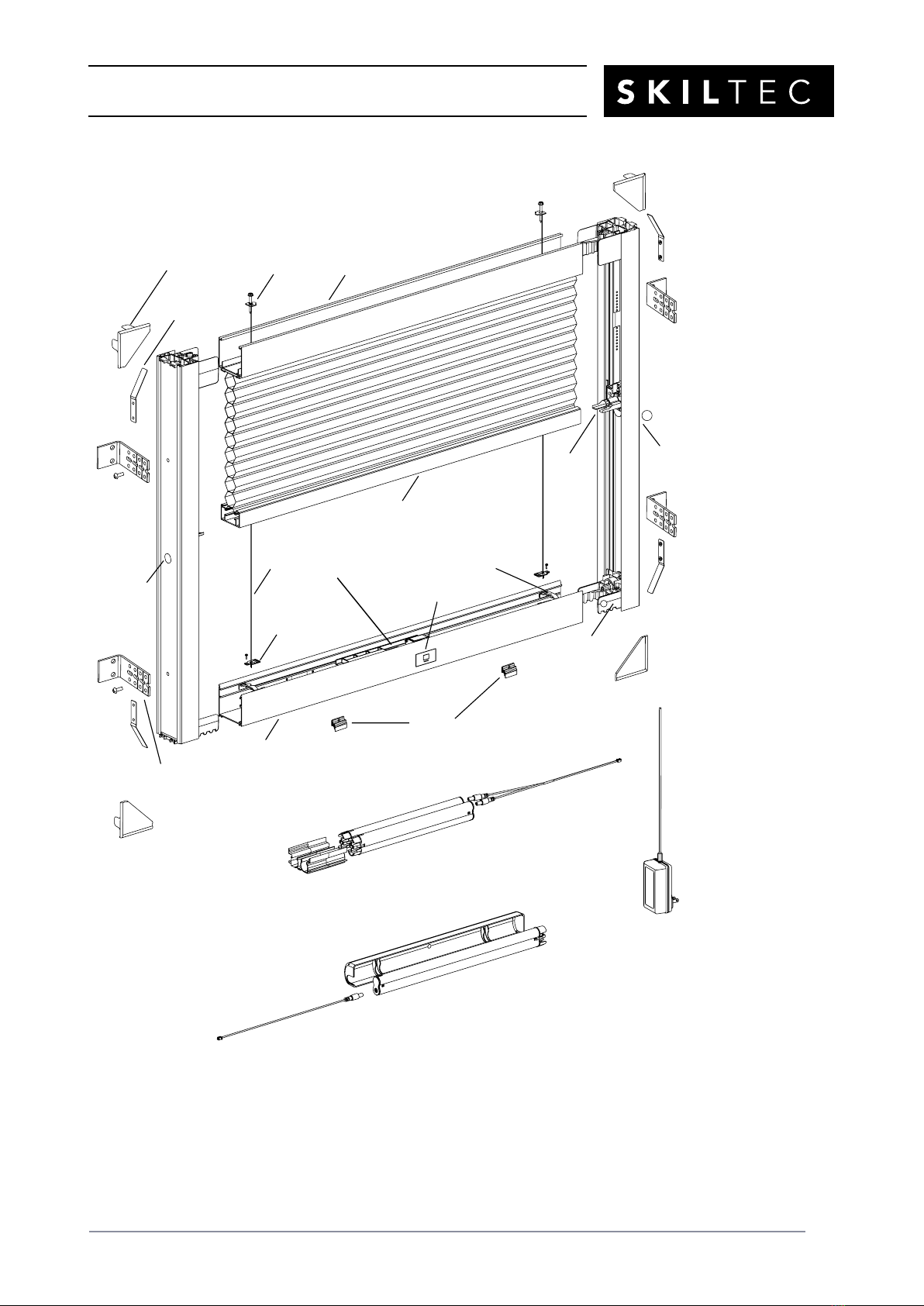
SKILTEC 9E DUETTE SKYLIFT POWERVIEW SYSTEM Dimensional drawing

9E DUETTE®SKYLIFT
POWERVIEW®SYSTEM
PRODUCT INFORMATION MANUAL
SECTION: 9E DUETTE®SKYLIFT POWERVIEW®SYSTEM

PRODUCT INFORMATION MANUAL
SECTION: 9E DUETTE®SKYLIFT POWERVIEW®SYSTEM
ISSUE DATE: NOVEMBER 2017 ORIGINATOR: SKILTEC
REPLACES ISSUE DATE: APPROVED BY: R.BOKTOR PAGE 3
3
Product View
Top Rail
Bottom Rail
Inside Mount
Installation
Bracket
Side
Rail
(Left)
Moving
Rail
Manual
Control
Button
Bottom
Corner
Bracket
Satellite Battery Pack
Battery Wand
(For Shades Less than 787mm)
Battery Wand
Cover
Battery Power Cable
Battery Power Cable
Battery Wands
Holder
Spacer
Blocks
Battery Wands
(For 787mm and Wider Shades)
DC Power
Supply (Optional)
Moving
Rail
End Cap
Top
Corner
Bracket
Tension
Cable
Bottom Tension
Plate and Screw
Outside Mount
Installation
Bracket
Tension Screw
and
Top Tension
Plate
Corner Cover
Side
Rail
(Right)
Tension Cable
Bracket
Motor
Assembly
R
L
R
PRODUCT INFORMATION MANUAL
SECTION: 9E DUETTE®SKYLIFT POWERVIEW®SYSTEM
ISSUE DATE: NOVEMBER 2017 ORIGINATOR: SKILTEC
REPLACES ISSUE DATE: APPROVED BY: R.BOKTOR PAGE 4
Thank you for purchasing Luxaflex®Duette®SkyLift Shades. With proper installation, operation,
and care, your new shades will provide years of beauty and performance.
Please thoroughly review this instruction booklet and the enclosed packing list before beginning
the installation.
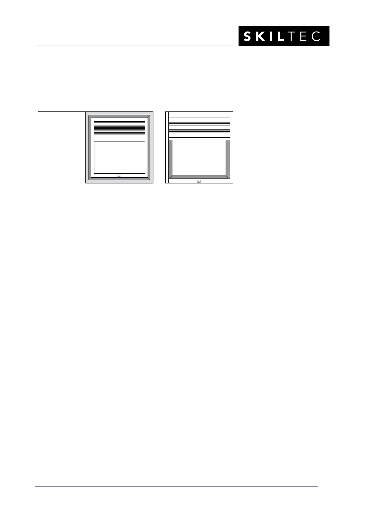
Mounting Types
CAUTION: This shade cannot be installed as a “side stack” shade, operating from side-to-side
within the window. Also, it cannot be installed as a “top-down” shade, where the fabric stack is
at the bottom of the window.
Tools Needed
■Allen Key (provided)
■Level (laser level is recommended)
■Measuring tape and pencil
■Needle-nose pliers
■Phillips screwdriver (magnetized screwdriver is recommended)
■Power drill,
3
/
32
" drill bit, and
1
/
4
" hex key
■Sharp scissors
■Tape
Reveal Mount
Shade fits within
window opening.
Face Mount
Shade mounts outside
window opening.

PRODUCT INFORMATION MANUAL
SECTION: 9E DUETTE®SKYLIFT POWERVIEW®SYSTEM
ISSUE DATE: NOVEMBER 2017 ORIGINATOR: SKILTEC
REPLACES ISSUE DATE: APPROVED BY: R.BOKTOR PAGE 5
Arrange the Shade Components for Assembly
■Unwrap the shade components.
■Clear a large, clean space on the floor and position the components for assembly.
■Remove the bubble wrap from the shade.
■Orient the top rail with the fabric colored side facing up and the bottom rail with the manual
control button facing up. Arrange the side rails with the “L” sticker on the left and the “R”
sticker on the right. Orient the side rails so that the top corner brackets are at the top and
the bottom corner brackets are at the bottom.
■Slide the moving rail end caps close to the top corner brackets.
“L” “R”
Top Corner Bracket Moving Rail End Cap
- Left
Moving Rail End Cap
- Right
Bottom Corner Bracket
Grey White
PRODUCT INFORMATION MANUAL
SECTION: 9E DUETTE®SKYLIFT POWERVIEW®SYSTEM
ISSUE DATE: NOVEMBER 2017 ORIGINATOR: SKILTEC
REPLACES ISSUE DATE: APPROVED BY: R.BOKTOR PAGE 6
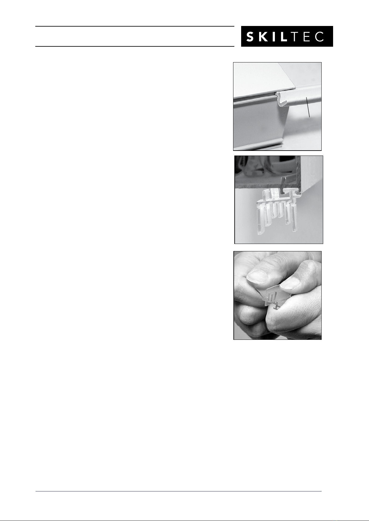
■Reveal Mount shades only: Light gap seals should be
inserted into the front channel of all four rails. Make
sure they are inserted in the correct orientation, as
shown.
■Reveal Mount shades only: If the angle of the installed shade will be
45° or steeper, slide two spacer blocks into the rear channel on the
underside of the bottomrail. The spacer blocks prevent the light gap seal
from over-compressing and ensure even positioning of the shade in the
casement.
■Position the spacer blocks approximately a quarter the shade
widthfrom each end of the bottom rail.
■The plastic spacer blocks have tabs of 13mm, 10mm, and 6mm. If
necessary, break off the outer tabs to adjust the spacer block to the
appropriate size, so the shade fits evenly into thecasement.
NOTE: The spacer blocks are packaged with the corner covers.
Front of Shade
Light Gap
Seal
Back
of
Shade

PRODUCT INFORMATION MANUAL
SECTION: 9E DUETTE®SKYLIFT POWERVIEW®SYSTEM
ISSUE DATE: NOVEMBER 2017 ORIGINATOR: SKILTEC
REPLACES ISSUE DATE: APPROVED BY: R.BOKTOR PAGE 7
Insert the Top Tension Plates in Place
IMPORTANT: Make sure the bottom rail and the bottom corner bracket with the “R” sticker are
placed on the right side before beginning the assembly.
■Position the left side rail close to the top rail.
■Orient and insert the top left tension plate in the slot in the top corner bracket on the left
side rail.
TIP: Tilt the screwhead up to insert the top tension plate first, then insert the screwhead in
place.
■Place a strip of tape over the screwhead to
keep the screw in place.
■Repeat the above steps on the right side.
■If there are more than two tension cables: Make sure all the top tension screw(s) and the
top tension plate(s) are in place.
PRODUCT INFORMATION MANUAL
SECTION: 9E DUETTE®SKYLIFT POWERVIEW®SYSTEM
ISSUE DATE: NOVEMBER 2017 ORIGINATOR: SKILTEC
REPLACES ISSUE DATE: APPROVED BY: R.BOKTOR PAGE 8
Attach the Side Rails to the Top and Bottom Rails
Attach the Left Side Rail to the Top Rail
■Insert the top left corner bracket into the top rail and
the moving rail end cap into the moving rail, while
keeping the fabric stacked.
IMPORTANT: Make sure both prongs of the
moving rail end cap are in the bottom channel of
the moving rail.
CAUTION: Be careful not to entangle the cable
with any of the shade components.
■Stack the fabric evenly near the top rail.
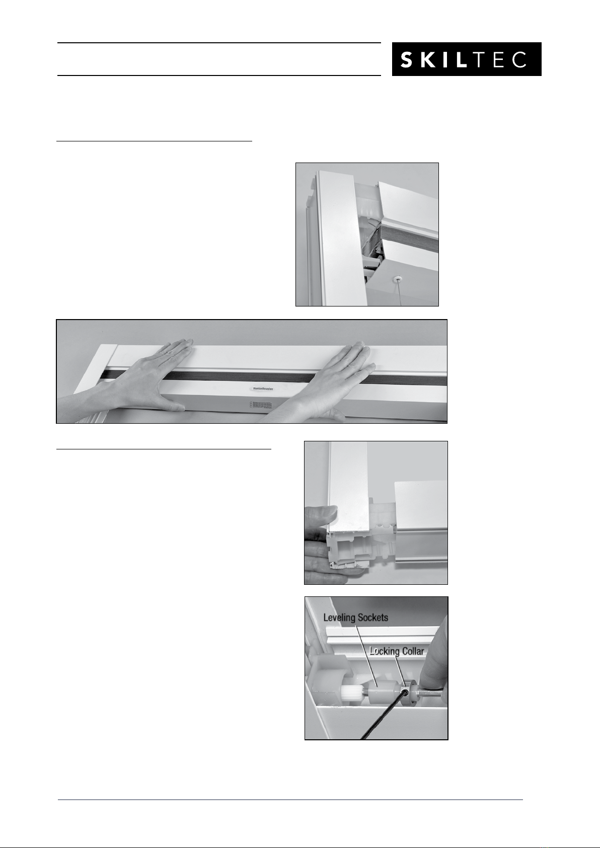
Attach the Left Side Rail to the Bottom Rail
■Insert the bottom left corner bracket into the
bottom rail.
■Align the left end of the shaft in the bottom rail with
the drive gear shaft.
■Slide the leveling socket onto the shaft and tighten the
locking collar using the provided Allen key.
Leveling Sockets
Locking Collar

PRODUCT INFORMATION MANUAL
SECTION: 9E DUETTE®SKYLIFT POWERVIEW®SYSTEM
ISSUE DATE: NOVEMBER 2017 ORIGINATOR: SKILTEC
REPLACES ISSUE DATE: APPROVED BY: R.BOKTOR PAGE 9
Attach the Right Side Rail to the Top Rail
■Insert the top right corner bracket into the top rail
and the moving rail end cap into the moving rail,
while keeping the fabric stacked.
IMPORTANT: Make sure both prongs of the
moving rail end cap are in the bottom channel of
the moving rail.
CAUTION: Be careful not to entangle the cable
with any of the shade components.
■Stack the fabric evenly near the top rail.
Attach the Right Side Rail to the Bottom Rail
■Insert the bottom right corner bracket into the
bottom rail.
■Align the right end of shaft in the bottom rail with the
drive gear shaft.
■Slide the leveling socket onto the shaft and tighten the locking
collar using the provided Allen key.
Leveling Sockets
Locking Collar
PRODUCT INFORMATION MANUAL
SECTION: 9E DUETTE®SKYLIFT POWERVIEW®SYSTEM
ISSUE DATE: NOVEMBER 2017 ORIGINATOR: SKILTEC
REPLACES ISSUE DATE: APPROVED BY: R.BOKTOR PAGE 10
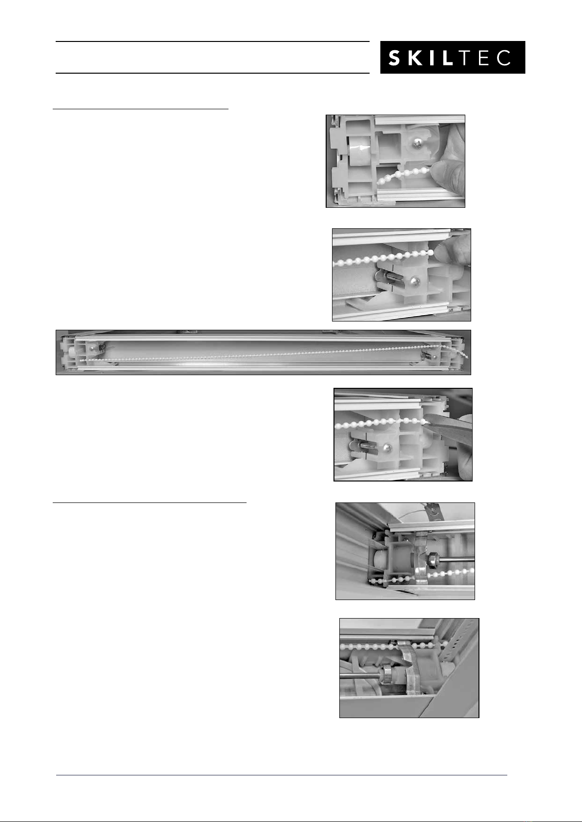
Secure the Side Rails to the Top Rail
■Hook one end of the bead chain between the third
and fourth bead from the end in the slot in the top
left corner bracket.
■Pull the bead chain taut and secure the other end
of the bead chain in the slot in the top right corner
bracket.
IMPORTANT: Make sure the bead chain is taut in order to hold
the side rails together.
■Cut the excess bead chain, leaving 3 to 4 extra beads
past the slot.
Secure the Side Rails to the Bottom Rail
■Hook one end of bead chain between the third and
fourth bead from the end in the slot in the bottom left
corner bracket.
■Pull the bead chain taut and secure the other end
of bead chain in the slot in the bottom right corner
bracket.
IMPORTANT: Make sure the bead chain is under
the tension cable brackets and taut in order to hold
the side rails together.

PRODUCT INFORMATION MANUAL
SECTION: 9E DUETTE®SKYLIFT POWERVIEW®SYSTEM
ISSUE DATE: NOVEMBER 2017 ORIGINATOR: SKILTEC
REPLACES ISSUE DATE: APPROVED BY: R.BOKTOR PAGE 11
Insert the Bottom Tension Plates in Place
■Place the bottom rail tension plate under the tension
cable bracket in the bottom rail on the left side.
■If you moved the tension cable bracket out of
the way, move it back against the bottom corner bracket.
■If the tension plate does not reach the tension
cable bracket, check that the cable is not tangled with the top
corner bracket.
IMPORTANT: Make sure the tension cable is in
the slot.
■Locate the bottom tension plate screws in the
package, place the screw in the screw hole in the
left bottom tension plate and tighten it to keep the tension plate in
place.
■Repeat the above steps on the right side.
■If there are more than two tension cables: Repeat
the above steps for each tension plate.
Install the Bottom Rail Cover
■Center the bottom rail cover on the bottomrail.
■Angle the cover into the back groove thendown.
■Press the front of the cover into the front groove.
Tension Cable
Bracket
Tension
Plate
Tension Cable
Bracket
Tension
Plate

PRODUCT INFORMATION MANUAL
SECTION: 9E DUETTE®SKYLIFT POWERVIEW®SYSTEM
ISSUE DATE: NOVEMBER 2017 ORIGINATOR: SKILTEC
REPLACES ISSUE DATE: APPROVED BY: R.BOKTOR PAGE 12
■Make sure all the tension cables are in the center of
the holes in the rail cover.
■Move the tension cable bracket(s) if necessary.
IMPORTANT: Be sure the cover is centered on the bottom rail.
■To remove the bottom rail cover: Place your finger
under one edge of the cover and pull it up while
spreading the bottom rail with your other hand. Once
you get an edge started, continue pulling the cover
up and out of the slot.
Adjust the Tension
■Remove the tape and tighten all the top tension screws
in the top rail until the tension plates line up with the
mark.
PRODUCT INFORMATION MANUAL
SECTION: 9E DUETTE®SKYLIFT POWERVIEW®SYSTEM
ISSUE DATE: NOVEMBER 2017 ORIGINATOR: SKILTEC
REPLACES ISSUE DATE: APPROVED BY: R.BOKTOR PAGE 13
Connect the Power Source
NOTE: When power is connected to the motor, a green LED below the manual control button
will flash to indicate the shade is ready for operation.
■Refer to the appropriate page based on your order.
■For battery wands (787mm and wider shades), see below.
■For a satellite battery pack (for shade less than 787mm), see “If You Have a Satellite
Battery Pack...” on page 14.
■For an optional DC power supply, see “If You Have a DC Power Supply...” on page 13.
If You Have Battery Wands...
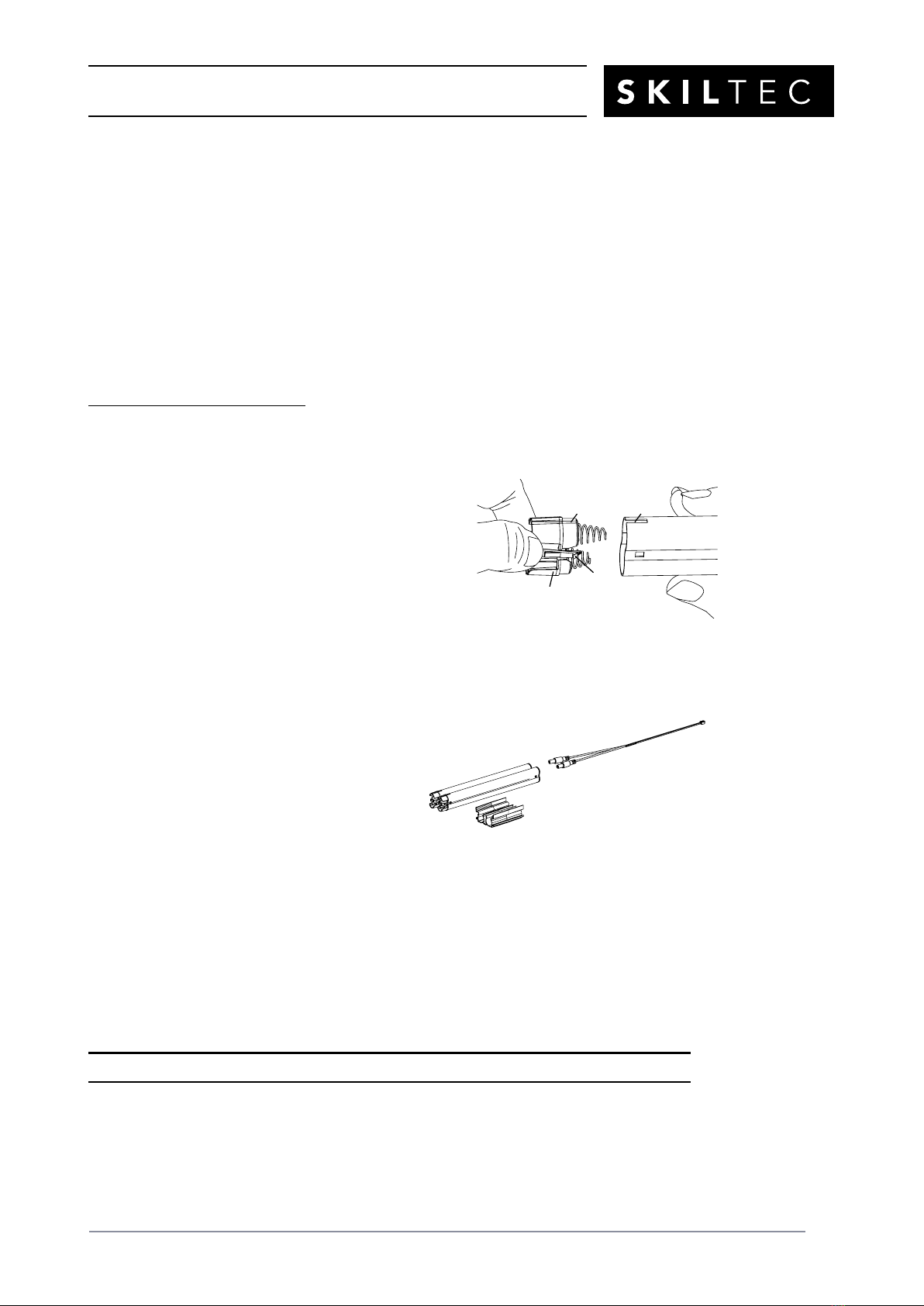
Install the Batteries into the Battery Wands
■Squeeze the cap latch to release and remove thecap.
■Install AA Lithium batteries according to the instructions
on on
the battery wand label.
■Replace the cap.
■Align the tab with the end of the wand.
■Press the cap on until it latches.
Mount the Battery Wands into theBatteryWandHolder
■Remove the bottom rail cover.
■Align the battery wands with the sockets toward
the motor.
■Push the battery wands straight down into the
battery wand holder in the bottom rail.
CAUTION: Be sure the cable does not become
pinched by the battery wand holder during
installation. Damage or overheating of components could result.
Plug the Power Cable into the Battery Wand
■Connect the power cable into the both sockets on the battery wands.
■Make sure the cable is not wrapped around the shaft.
■Reinstall the bottom railcover.
Proceed to ““Test the Shade” on page 16.
Tab Slot
Cap
Latch
Battery
Wand
Squeeze
Battery Wand
Holder
Battery Wand
PRODUCT INFORMATION MANUAL
SECTION: 9E DUETTE®SKYLIFT POWERVIEW®SYSTEM
ISSUE DATE: NOVEMBER 2017 ORIGINATOR: SKILTEC
REPLACES ISSUE DATE: APPROVED BY: R.BOKTOR PAGE 14
If You Have a Satellite Battery Pack...
Install the Batteries into the Battery Wand
■Squeeze the cap latch to release and remove thecap.
■Install AA Lithium batteries according to the instructions
on on
the battery wand label.
■Replace the cap.
■Align the tab with the end of the wand.
■Press the cap on until it latches.
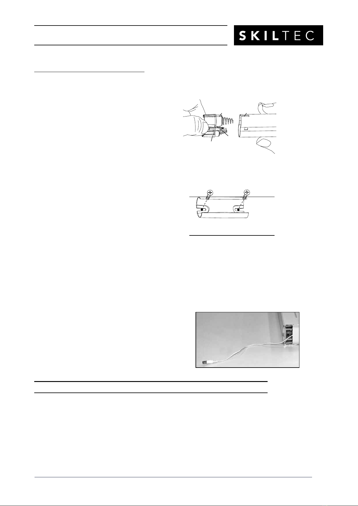
Mount the Satellite Battery Pack Behind the Bottom Rail
■Remove the bottom rail cover.
■Attach the wall mount bracket to the back side of
the bottom rail using the pre-drilled holes.
■Remove the screws attached to the back side of the
bottom rail.
■Attach the wall mount bracket using those screws.
NOTE: With the satellite battery pack behind the shade, the minimum casement depth for
fully recessed mounting is 115mm. If there is not enough clearance for the satellite battery
pack to be mounted on the back side of the bottom rail, it may be mounted on the wall or
ceiling in any orientation. See “Mount the Satellite Battery Pack on the Wall or Ceiling” on
page 19.
■Route the power cable from the shade
through the bottom left corner bracket and
plug into the socket in the battery wand or
the extension cable.
■If using an extension cable, plug the
other end of the extension cable into
the socket in the battery wand.
■Reinstall the bottom railcover.
Proceed to ““Test the Shade” on page 16.
Tab Slot
Cap
Latch
Battery
Wand
Squeeze
Wall Mount Bracket
Back of
Bottom Rail
PRODUCT INFORMATION MANUAL
SECTION: 9E DUETTE®SKYLIFT POWERVIEW®SYSTEM
ISSUE DATE: NOVEMBER 2017 ORIGINATOR: SKILTEC
REPLACES ISSUE DATE: APPROVED BY: R.BOKTOR PAGE 15
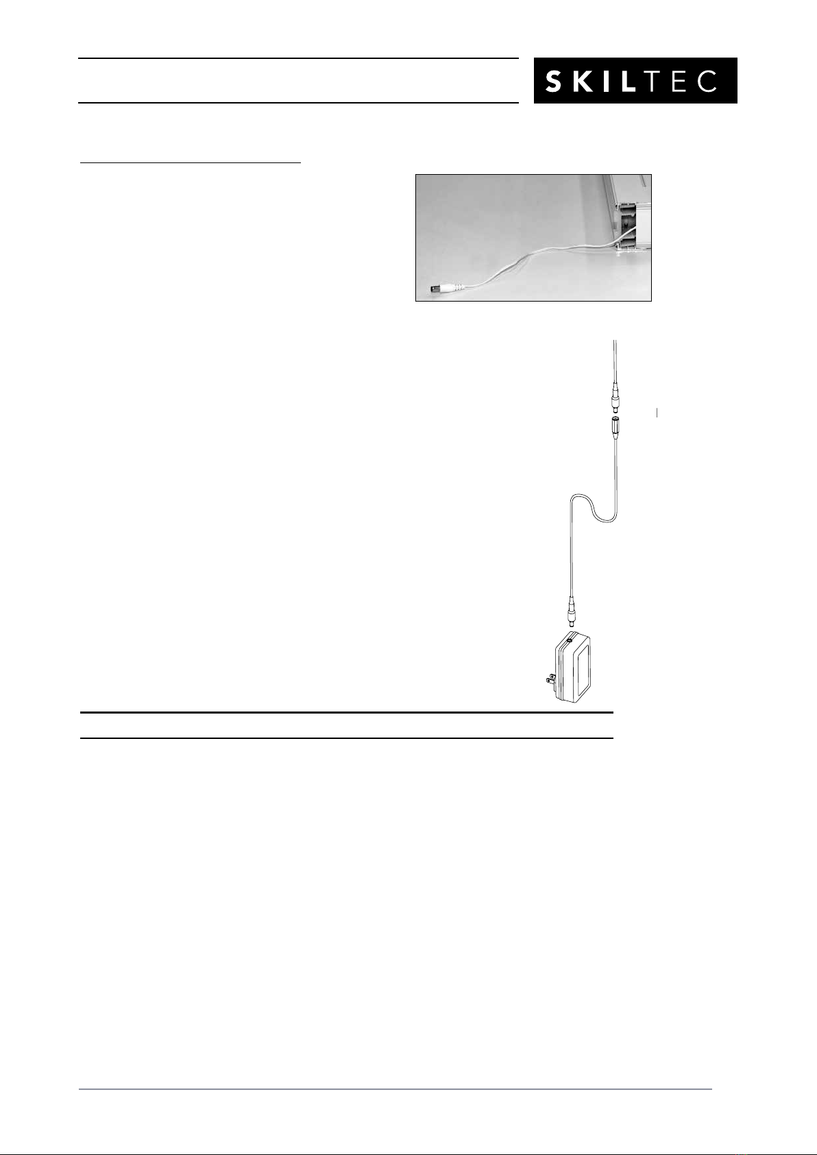
If You Have a DC Power Supply...
Connect the Power Supply
■Remove the bottom rail cover.
■Route the power cable from the shade through
the bottom left corner bracket and plug into the
extension cable.
■Reinstall the bottom railcover.
■Plug the other end of the extension cable into the DC power supply.
■Plug the DC power supply into a standard wall outlet.
■The power supply may be oriented with the cable at the top or bottom.
Proceed to ““Test the Shade” on page 16.
Power Cable
from Shade
Extension
Cable
DC
Power
Supply
380mm
Maximum
Wire Retainers

PRODUCT INFORMATION MANUAL
SECTION: 9E DUETTE®SKYLIFT POWERVIEW®SYSTEM
ISSUE DATE: NOVEMBER 2017 ORIGINATOR: SKILTEC
REPLACES ISSUE DATE: APPROVED BY: R.BOKTOR PAGE 16
Test the Shade
Prior to installing the shade in the window, test its operation using the manual control button and
the PowerView®remote.
■Press the manual control button to alternately lower, stop, and raise the shade.
■If the shade does not operate correctly, see “Troubleshooting” on page 26.
■Follow the instructions “Using the PowerView Remote” on page 21 and set up a remote. Test
the shade operation to verify that the side rails are assembled correctly.
■Press and release ▲ OPEN to make sure the shade moves up.
■Press and release ▲CLOSE to make sure the shade moves down.
IMPORTANT: If the shade moves opposite of the command, disassemble the shade and
switch out the side rails.
■If you used the wall or ceiling mounted satellite battery pack or the DC power supply to test
the shade, disconnect the extension cable from the battery pack or the power supply until
you complete the installation.
Adjust the Shade (If Necessary)
■Raise the moving rail approximately 300mm above the bottom rail and check the level of the
moving rail.
■Measure the distance from the bottom rail to the moving rail on the left and right sides. If
the distances are not equal, you must adjust the rail to level it.
■Adjust one side of the moving rail if necessary.
■Remove the bottom rail cover.
■Loosen a locking collar on one side and slide the
leveling socket off the shaft.
■Adjust the moving rail on the side where the leveling socket is
off the drive shaft.
■After the moving rail is level, slide the leveling socket onto the
drive gear shaft and tighten the locking collar.
■Operate the shade to verify that the shade is level. Repeat the
above steps, if necessary.
■Reinstall the bottom railcover.

PRODUCT INFORMATION MANUAL
SECTION: 9E DUETTE®SKYLIFT POWERVIEW®SYSTEM
ISSUE DATE: NOVEMBER 2017 ORIGINATOR: SKILTEC
REPLACES ISSUE DATE: APPROVED BY: R.BOKTOR PAGE 17
Install the Shade — Reveal Mount
Your order will include four installation brackets per shade
and two mounting screws per installation bracket, plus four
extra screws.
Trim the Light Gap Seals
■Trim the excess light gap seal at all
four corners with sharp scissors.
Mount the Installation Brackets
■Starting with the bottom right corner
of the skylight opening, hold the
provided SkyLift Inside Mount
Bracket Template with the
arrow toward the glass.
■Line up the front edge of the jamb with the dotted line
located at the
2 1/2" (65mm) mark on the template.
IMPORTANT: If you are installing a satellite battery
pack behind the bottom rail, line up the front edge
of the jamb with the dotted line located at the 4 1/2"
(115mm) mark.
■Mark the screw holes.
■Use the same side of the template
for the top left corner of the skylight
opening.
■Flip the template and use the
backside for the top right and the
bottom left corners.
■After marking all four corners, drill
the screw holes using a
3
/
32
" drill bit.
■Attach the installation brackets using
the screws provided.
Installation
Bracket
Installation
Brackets
Sill
Jamb

PRODUCT INFORMATION MANUAL
SECTION: 9E DUETTE®SKYLIFT POWERVIEW®SYSTEM
ISSUE DATE: NOVEMBER 2017 ORIGINATOR: SKILTEC
REPLACES ISSUE DATE: APPROVED BY: R.BOKTOR PAGE 18
Mount the Shade
■Slip the upper portion of the
shade into the window frame.
Make sure the installation
brackets fit into the notches
on the plastic hooks (inset).
■Slip a screwdriver behind the shade and push back the
brackets to install the lower
end of the shade.
■Additional holes are punched in the side rails 200mm
from
each corner. You may attach the side rails to the window
frame using the provided extra screws.
IMPORTANT: Do not overtighten these screws. Doing so
can cause the side rails to bow in and prevent the shade
from operating correctly.
NOTE: Additional screws can be added to secure the larger
shades. If you choose to use more screws, drill installation
holes on the screw indicator grooves in the side rails.
Attach the Corner Covers
■Remove the adhesive backing from the corner covers.
■Press a cover onto each shade corner, extending them to
the window frame to cover the light gap.
If you have the wall or ceiling mounted satellite battery pack or the DC
power supply,
proceed to “Finish Mounting the Power Supply” on page 19
or “Finish Mounting the Power Supply” on page 21 21.
Screw Indicator
Grooves
Corner
Cover
PRODUCT INFORMATION MANUAL
SECTION: 9E DUETTE®SKYLIFT POWERVIEW®SYSTEM
ISSUE DATE: NOVEMBER 2017 ORIGINATOR: SKILTEC
REPLACES ISSUE DATE: APPROVED BY: R.BOKTOR PAGE 19
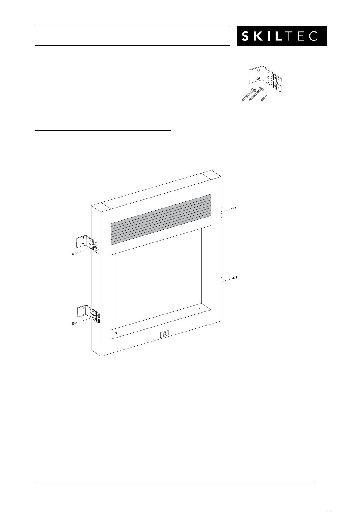
Install the Shade — Face Mount
Your order will include four installation brackets (two for each side rail)
as well as one 10mm screw and two 38mm screws per installation bracket.
IMPORTANT: You may need another person to assist you with
this installation.
Attach the Installation Brackets to the Shade
■Attach the installation brackets to the shade through pre-drilled holes on the side rails using
the 10mm screws provided.
PRODUCT INFORMATION MANUAL
SECTION: 9E DUETTE®SKYLIFT POWERVIEW®SYSTEM
ISSUE DATE: NOVEMBER 2017 ORIGINATOR: SKILTEC
REPLACES ISSUE DATE: APPROVED BY: R.BOKTOR PAGE 20
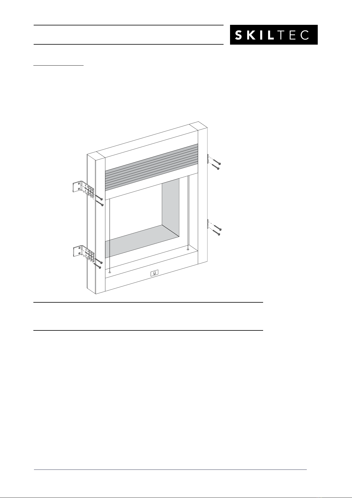
Mount the Shade
■Place the shade over the window opening at the desired location.
■Mark the screw holes and drill them using a
3
/
32
" drill bit.
CAUTION: Use drywall anchors when mounting into drywall.
■Attach the installation brackets to the mounting surface using the 38mm screws provided.
If you have the wall or ceiling mounted satellite battery pack or the DC power supply,
proceed to “Finish Mounting the Power Supply” on page 19
or “Finish Mounting the Power Supply” on page 21 21.
Table of contents
Other SKILTEC Indoor Furnishing manuals


Popular Indoor Furnishing manuals by other brands

Regency
Regency LWMS3015 Assembly instructions

Furniture of America
Furniture of America CM7751C Assembly instructions

Safavieh Furniture
Safavieh Furniture Estella CNS5731 manual

PLACES OF STYLE
PLACES OF STYLE Ovalfuss Assembly instruction

Trasman
Trasman 1138 Bo1 Assembly manual

Costway
Costway JV10856 manual


