ISSUE DATE: NOVEMBER 2017 ORIGINATOR: SKILTEC
REPLACES ISSUE DATE: APPROVED BY: D.ALTIPARMAKOVA PAGE 20
PRODUCT INFORMATION MANUAL
SECTION: 9F-2 DUETTE®POWERVIEW®MOTORISATION
Resetting the Shade, If Necessary
Basic Reset
The basic reset is used to reset the shade’s travel limits.
Bottom-Up Shades:
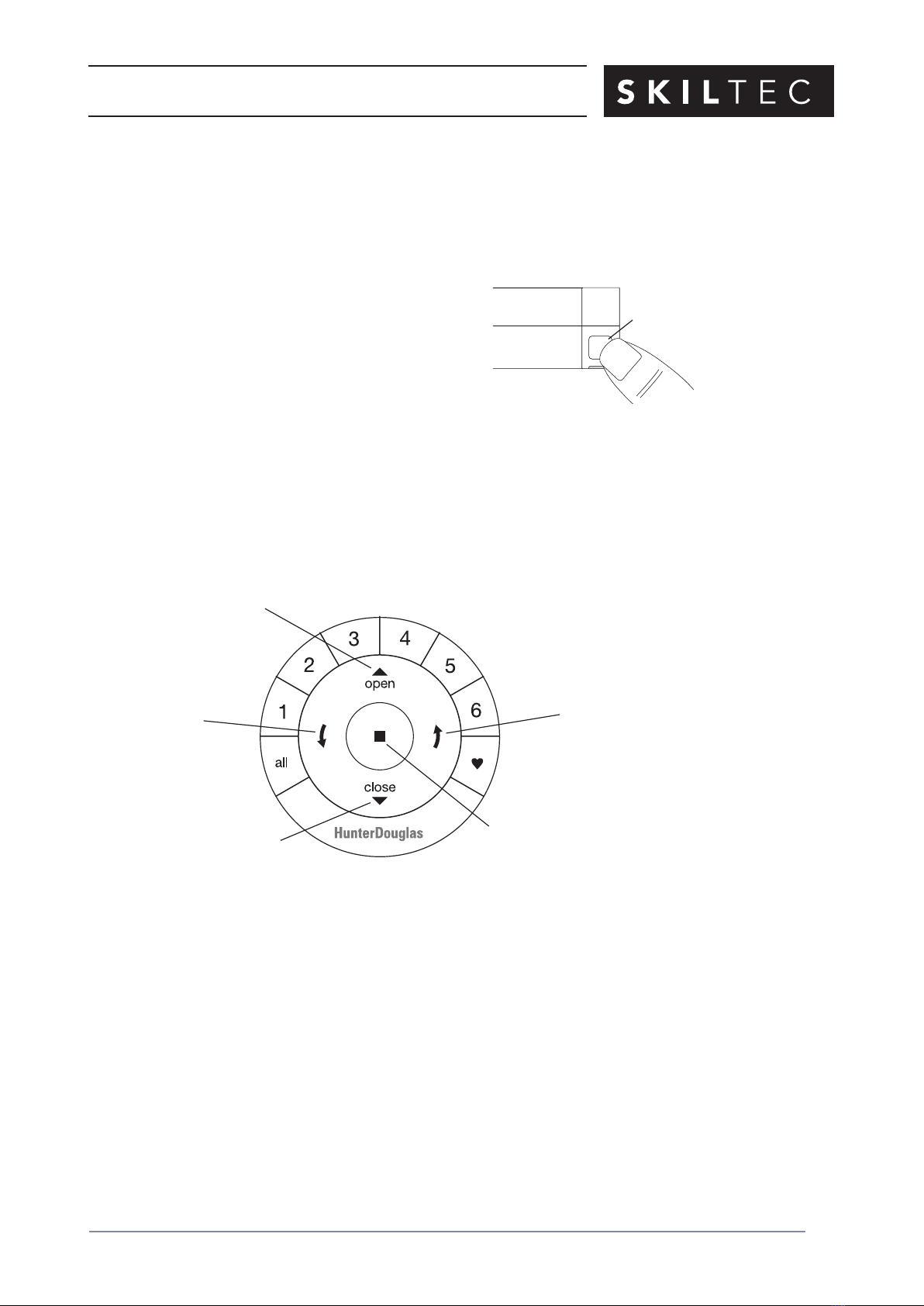
1. Press and hold the manual control button for 6 seconds. The shade will move slightly.
2. Release the manual control button. The shade will raise to its fully open position to set the
upper travel limit, then lower to the fully closed position to set the lower travel limit. The shade
will move slightly one more time to indicate that the travel limits have been reset.
Top-Down Shades:
1. Press and hold the manual control button for 6 seconds. The shade will move slightly.
2. Release the manual control button. The middle rail will raise, closing the shade to set the
upper travel limit, then lower, opening the shade to set the lower travel limit. The shade will
move slightly one more time to indicate that the travel limits have been reset.
Top-Down/Bottom-Up and Duolite™Shades:
1. Press and hold the manual control button for 6 seconds. The shade will move slightly.
2. Release the manual control button. The middle rail will raise to the top, followed by the bottom
rail, opening the shade bottom-up to set the upper travel limits. The bottom rail will then
lower, followed by the middle rail, opening the shade top-down to set the lower travel limits.
The shade will move slightly one more time to indicate that the travel limits have been reset.
Resetting Shade Programming
This reset erases all shade programming from memory, including group assignments, preventing
any input device from operating the shade. Its primary use is during installation to correct group
and network assignments. This reset does not affect travel limits.
1. Press and hold the manual control button for 12 seconds. The shade will move slightly once
after 6 seconds, then again after 12 seconds. Release the button.
2. Refer to “Joining a Shade to a Group” on page 16 to program the shade to a group.