SKILTEC DUETTE VERTIGLIDE SIDE STACK DESIGNPOWERVIEW MOTORISATION... Dimensional drawing
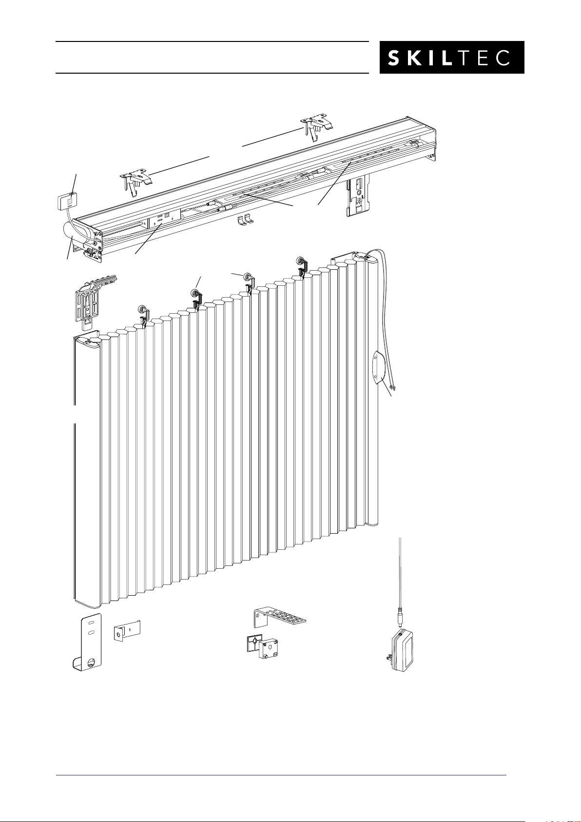
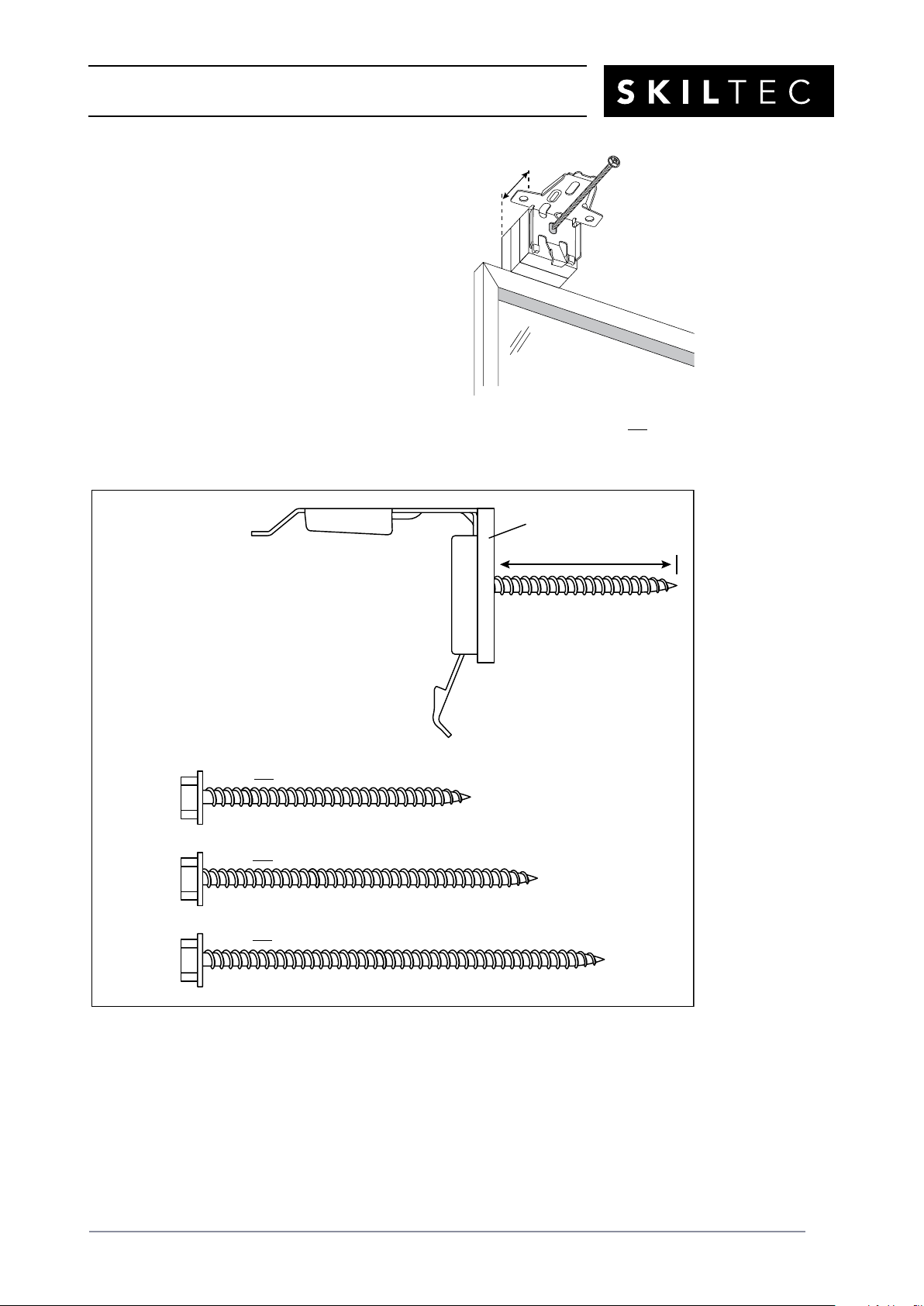
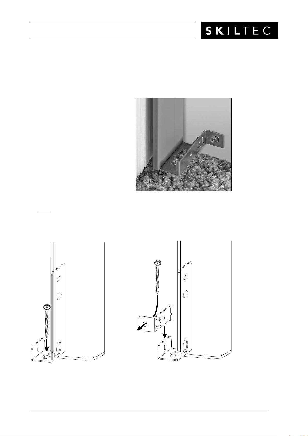
DUETTE®VERTIGLIDE™
SIDE STACK DESIGN
POWERVIEW®MOTORISATION
PRODUCT INFORMATION MANUAL
SECTION: 9G-B DUETTE®VERTIGLIDE™SIDE STACK DESIGN
POWERVIEW®MOTORISATION


PRODUCT INFORMATION MANUAL
SECTION: 9G-B DUETTE®VERTIGLIDE™SIDE STACK DESIGN
POWERVIEW®MOTORISATION
ISSUE DATE: NOVEMBER 2017 ORIGINATOR: SKILTEC
REPLACES ISSUE DATE: APPROVED BY: D.ALTIPARMAKOVA PAGE 3
Product View
Left Stack Shown
Stationary
Rail
Bracket
Tension
Cord
Handle
Stationary Rail
Bottom Bracket
*Located inside headrail
Inside
Mount
Adaptor
Moving
Rail
Fabric Carriers
Extension
Bracket
Optional Outside Mount Hardware:
3mm Shim 13mm Spacer
Block
Stationary
Rail
Extension
Cable
DC Power Supply
(Optional)
Headrail
Gearbox
Cord
Tensioners*
Battery
Wands
Moving
Rail
Bracket*
Manual
Control Button
Motor
Installation
Brackets

PRODUCT INFORMATION MANUAL
SECTION: 9G-B DUETTE®VERTIGLIDE™SIDE STACK DESIGN
POWERVIEW®MOTORISATION
ISSUE DATE: NOVEMBER 2017 ORIGINATOR: SKILTEC
REPLACES ISSUE DATE: APPROVED BY: D.ALTIPARMAKOVA PAGE 4
Thank you for purchasing Luxaflex®Duette®Vertiglide™honeycomb shades. With proper
installation, operation, and care, your new shades will provide years of beauty and performance.
To get started, unpack the shade and remove all foam/
packaging materials. Check that all parts shown on
the packing list are included with the order.
Please thoroughly review this instruction booklet before
beginning the installation.
IMPORTANT: Cords are wrapped around a
cord organizer located approximately 152mm
from the top of the moving rail. Please do not
unwrap the cords until instructed to do so.
Tools and Fasteners Needed
■Flat blade and magnetic-tipped Phillips screwdrivers
■Level (laser level is recommended)
■Measuring tape and pencil
■Power drill, 3mm
drill bit, and 6mm hex driver
■Scissors
In addition, you will need fasteners designed to work with your specific mounting surface(s).
■#6 Hex Head Screws (Provided). Two 38mm screws are provided per installation bracket.
■Longer #6 Hex Head Screws (Not Provided). If using spacer blocks, use #6 screws long
enough for a secure attachment.
■Speed Nuts and Screws (Provided). Extension brackets come with speed nuts and screws.
■Drywall Anchors (Not Provided). Use drywall anchors when mounting into drywall.
Installation Brackets Required
■The number of installation brackets required varies with headrail width, as
shown in the table.
Speed Nut
and Screw
(Two Provided with
Each Extension Bracket)
#6 x 38mm
Hex Head Screw
(Provided)
Longer #6 Hex Head Screw
for Use with Spacer Blocks
(Not Provided)
Do Not
Unwrap
Cords
NOTE: Two installers are recommended for shades
over 2130mm wide.
Shade
Width
Brackets
Required
310mm – 788mm 2
789mm – 1675mm 3
1676mm – 2440mm 4
2441mm – 3531mm 5
3532mm – 4270mm 6

PRODUCT INFORMATION MANUAL
SECTION: 9G-B DUETTE®VERTIGLIDE™SIDE STACK DESIGN
POWERVIEW®MOTORISATION
ISSUE DATE: NOVEMBER 2017 ORIGINATOR: SKILTEC
REPLACES ISSUE DATE: APPROVED BY: D.ALTIPARMAKOVA PAGE 5
Installation Overview
Installation of Vertiglide™shades varies based on the shade mounting type and stacking design
selected.
Mounting Types and Window Terminology
■Review the mounting types and basic window terminology illustrated below. Determine if
your shade is an outside mount or inside mount. For ceiling mount applications, refer to the
inside mount instructions.
Stacking Designs
■Determine which Vertiglide stacking design you are installing: left stack or right stack.
■If a sliding glass door opens from the right side, a left stack design is best. If the door opens
from the left side, a right stack design is best.
NOTE: A left stack design is shown throughout these instructions. Procedures for a right stack
design are the same but at opposite sides of the fabric stack and headrail.
Next Step
■Refer to the page below based on your shade mounting type:
➤Face Mount — Page <?>
➤Reveal/Ceiling Mount — Page 9
Molding
Floor
Jamb Jamb
Head Jamb
Outside Mount
Shade mounts outside
door or window opening.
Inside Mount
Shade fits within door
or window opening.
Window or
Patio/Sliding Door
Left Stack Right Stack

PRODUCT INFORMATION MANUAL
SECTION: 9G-B DUETTE®VERTIGLIDE™SIDE STACK DESIGN
POWERVIEW®MOTORISATION
ISSUE DATE: NOVEMBER 2017 ORIGINATOR: SKILTEC
REPLACES ISSUE DATE: APPROVED BY: D.ALTIPARMAKOVA PAGE 6
Face Mount
Mount the Installation Brackets
■Center the headrail over the window opening at the desired height. Use a pencil to mark
each end of the headrail. (On the stacking side, the end of the white gearbox counts as the
end of the headrail.)
➤Alternatively, measure the width of the headrail and use that width to mark the headrail
end points.
■Mark end bracket locations 200mm in from each end of the headrail.
➤Mark the locations of any additional brackets, spaced evenly between the two end
brackets. Mount into wood whenever possible.
■Determine where to place the top of the installationbrackets.
➤Add the desired floor clearance to the ordered
height of the shade. The ordered height can be
found on the packaging label. A minimum of 13mm
floor clearance is recommended.
➤Measure the total distance up from the floor. This is
where to place the top of the installation brackets.
➤A minimum flat vertical surface of 32mm is required
to mount the brackets.
CAUTION: The rear of the brackets must be flush
against a flat mounting surface. Do not mount
brackets oncurved molding.
■Center the brackets on your marks and mark the screw holes.
➤When using extension brackets, mark two screw holes
per bracket.
Headrail End Marks
Window/Door Opening
8" 8"
Space Evenly Space Evenly
Top of
Bracket
FloorClearance
Ordered
Shade
Height

PRODUCT INFORMATION MANUAL
SECTION: 9G-B DUETTE®VERTIGLIDE™SIDE STACK DESIGN
POWERVIEW®MOTORISATION
ISSUE DATE: NOVEMBER 2017 ORIGINATOR: SKILTEC
REPLACES ISSUE DATE: APPROVED BY: D.ALTIPARMAKOVA PAGE 7
■Drill the screw holes using a 3mm drill bit.
CAUTION: Use drywall anchors when mounting into drywall. Use the drill bit size
recommended by the manufacturer.
■Attach the installation or extension brackets using the screws provided.
IMPORTANT: The front edges of the brackets must be level and aligned to each other.
■If using extension brackets, attach an installation bracket to
the underside of each extension bracket using theprovided
screws and speed nuts.
■If using spacer blocks, first attach the installation bracket to the
13mm spacer block before stacking additional spacer blocks or
shims together.
➤Insert the legs of the installation bracket into the tabs on the
spacer block.
➤Then rotate the installation bracket back.
➤Use a maximum of three spacer blocks (38mm) per installationbracket.
IMPORTANT: For the 38mm pleat size, a minimum 6mm rear clearance is recommended.
Tab

PRODUCT INFORMATION MANUAL
SECTION: 9G-B DUETTE®VERTIGLIDE™SIDE STACK DESIGN
POWERVIEW®MOTORISATION
ISSUE DATE: NOVEMBER 2017 ORIGINATOR: SKILTEC
REPLACES ISSUE DATE: APPROVED BY: D.ALTIPARMAKOVA PAGE 8
■Attach the spacer blocks and installation brackets
with #6hex head mounting screws long enough for
asecure installation. (See chart below.) Longer screws
are not provided.
➤The top of the spacer blocks should be at the
desired shade height.
➤The front edges of the installation brackets must
be level and aligned to each other.
CAUTION: Use drywall anchors when mounting
into drywall.
CAUTION: The rear of the spacer blocks must be flush against a flat surface. Do not mount
spacer blocks and installation brackets oncurved molding.
76mm (Not provided; up to 38mm of spacer blocks/shims)
64mm (Not provided; up to 29mm of spacer blocks/shims)
Never use more than 38mm of spacer blocks/shims!
IMPORTANT: The provided 38mm screws can only
be used with a maximum of one 3mm shim. You will
need to supply longer screws if additional
clearance is required.
A minimum 32mm length of screw threads must
extend beyond the last spacer block or shim.
Use appropriate wall anchors when mounting
into drywall.
51mm (Not provided; up to 16mm of spacer blocks/shims)
32mm Minimum
Shim
Maximum of One
Shim with Provided
38mm Screws
Longer Screw
(Not Provided)
Maximum
38mm

PRODUCT INFORMATION MANUAL
SECTION: 9G-B DUETTE®VERTIGLIDE™SIDE STACK DESIGN
POWERVIEW®MOTORISATION
ISSUE DATE: NOVEMBER 2017 ORIGINATOR: SKILTEC
REPLACES ISSUE DATE: APPROVED BY: D.ALTIPARMAKOVA PAGE 9
Mount the Headrail
■Mount the headrail into the installation brackets. Do not remove any components from the
headrail. Both end plates should remain attached to the ends of the headrail.
➤Carefully align the headrail with the end marks on the mounting surface. Headrail
position cannot easily be adjusted after the headrail is mounted. (Remember that the
end of the white gearbox is the end of the headrail on the stacking side.)
➤Place the front groove on the headrail onto the front lip of the installation brackets.
➤Rotate the rear of the headrail up and push back until the headrail snaps in place.
Proceed to “Install the Fabric Stack” on page 11.
Align Headrail with End Marks
Align End of
Gearbox with
End Mark
Snap in
Place
Place Groove onto
Front of Bracket

PRODUCT INFORMATION MANUAL
SECTION: 9G-B DUETTE®VERTIGLIDE™SIDE STACK DESIGN
POWERVIEW®MOTORISATION
ISSUE DATE: NOVEMBER 2017 ORIGINATOR: SKILTEC
REPLACES ISSUE DATE: APPROVED BY: D.ALTIPARMAKOVA PAGE 10
Reveal/Ceiling Mount
Mount the Installation Brackets
■Mark 200mm in from each jamb. This marks the center points of the two end brackets.
➤Mark the locations of any additional brackets, spaced evenly between the two end
brackets.
■Center the brackets on your marks and mark the screw holes.
➤The minimum casement depth for mounting the installation brackets is 13mm. Mark
both of the winged screw holes with shallow mounting depths.
➤The minimum casement depth for
a fully recessed mount varies with
valance type and fabric pleat size, as
shown in the table. Mark the center
screw hole when depth permits.
IMPORTANT: For the 38mm pleat size, a minimum 6mm rear clearance is
recommended.
■Drill the screw holes using a 3mm drill bit.
CAUTION: Use drywall anchors when mounting into drywall. Use the drill bit size
recommended by the manufacturer.
Window/Door Opening
200mm Space Evenly
Jamb Jamb
Space Evenly 200mm
Minimum
13mm Use Center Hole
When Depth Permits
Fully Recessed Depth
20mm Pleat
98mm

PRODUCT INFORMATION MANUAL
SECTION: 9G-B DUETTE®VERTIGLIDE™SIDE STACK DESIGN
POWERVIEW®MOTORISATION
ISSUE DATE: NOVEMBER 2017 ORIGINATOR: SKILTEC
REPLACES ISSUE DATE: APPROVED BY: D.ALTIPARMAKOVA PAGE 11
■Attach the installation brackets using the screwsprovided.
IMPORTANT: Be sure the front edges of the installation brackets are level and aligned to
eachother. Use shims if necessary to level the brackets.
Mount the Headrail
■Mount the headrail into the installation brackets. Do not remove any components from the
headrail. Both end plates should remain attached to the ends of the headrail.
➤Place the front groove on the headrail onto the front lip of the installation bracket.
➤Position the end of the headrail opposite the fabric stack flush against the jamb. This
leaves a gap on the stationary rail side. The stationary rail fills this gap when anchored.
➤Rotate the rear of the headrail up and push back until the headrail snaps in place.
Gap Left Stack Shown Flush
Place Groove onto
Front of Bracket
Snap in
Place

PRODUCT INFORMATION MANUAL
SECTION: 9G-B DUETTE®VERTIGLIDE™SIDE STACK DESIGN
POWERVIEW®MOTORISATION
ISSUE DATE: NOVEMBER 2017 ORIGINATOR: SKILTEC
REPLACES ISSUE DATE: APPROVED BY: D.ALTIPARMAKOVA PAGE 12
Install the Fabric Stack
NOTE: The installation procedures that follow are the same for Reveal and Face mounts, except
where indicated.
Prepare the Fabric Stack
■Insert the stationary rail bracket into the vertical rail on the side where the fabric stacks.
➤The bracket fits into the grooves on the rear of the vertical rail.
➤Insert the bracket until it is seated and the bracket catch snaps into the hole on the back
of the rail. Check that the bracket catch is fully engaged.
Bracket Catch
Seated Bracket

PRODUCT INFORMATION MANUAL
SECTION: 9G-B DUETTE®VERTIGLIDE™SIDE STACK DESIGN
POWERVIEW®MOTORISATION
ISSUE DATE: NOVEMBER 2017 ORIGINATOR: SKILTEC
REPLACES ISSUE DATE: APPROVED BY: D.ALTIPARMAKOVA PAGE 13
■Insert the stationary rail bottom bracket into the bottom of the stationary rail.
➤The bracket fits into grooves at the bottom of the rail.
➤Insert the bracket with the mounting flanges to the back, away from the fabric stack as
shown. Do not seat the bracket; about 6mm should extend from the rail.
➤After inserting the bracket, peel off the red label.
Install the Fabric Stack into the Headrail
■Insert the moving rail onto the moving rail bracket.
➤The bracket fits into the grooves on the rear of
the vertical rail. Be sure to fit the bracket into
both rear grooves.
➤Insert the bracket until the bracket catch snaps
into the hole on the back of the rail. Check that
the bracket catch is fully engaged.
Rear Grooves
Moving
Rail

PRODUCT INFORMATION MANUAL
SECTION: 9G-B DUETTE®VERTIGLIDE™SIDE STACK DESIGN
POWERVIEW®MOTORISATION
ISSUE DATE: NOVEMBER 2017 ORIGINATOR: SKILTEC
REPLACES ISSUE DATE: APPROVED BY: D.ALTIPARMAKOVA PAGE 14
■Review the diagram below to familiarize yourself with where the fabric carrier wheels fit
inside the headrail. Note that the headrail is notched to allow insertion of the wheels.
➤Above the notch is a foam block to keep the wheels in place during installation.
Compress the foam to install the fabric carrier wheels.
■Insert the fabric carrier wheels into the headrail through the notch on the stationary rail
side, compressing the foam block. (Unwrap a small amount of cord from the orange cord
organizer if you need more slack.)
➤The wheels with clear stems fit into the rear channel and the wheels with black stems
into the front channel.
NOTE: The fabric carrier wheels only fit into the rail the correct way; it is not possible to
install them into the wrong channel.
IMPORTANT: Do not attach the stationary rail bracket until after inserting all fabric carriers.
Black = Front Clear = Rear
Foam Block
Above Notch
Clear Stem
Fabric Carriers
Black Stem
Fabric Carriers
FRONT

PRODUCT INFORMATION MANUAL
SECTION: 9G-B DUETTE®VERTIGLIDE™SIDE STACK DESIGN
POWERVIEW®MOTORISATION
ISSUE DATE: NOVEMBER 2017 ORIGINATOR: SKILTEC
REPLACES ISSUE DATE: APPROVED BY: D.ALTIPARMAKOVA PAGE 15
■Install the stationary rail bracket.
➤Hook the stational rail bracket to the headrail as illustrated below.
➤After hooking it to the headrail, you may allow the stationary rail to hang freely.
■Position the stationary rail bracket.
➤To move the stationary rail bracket, pull the bottom of the rail into the room slightly
before sliding the bracket.
➤Face Mount: Move the stationary rail bracket so that the stationary rail is aligned with
the end of the white gearbox.
➤Reveal Mount: Move the stationary rail bracket so that the stationary rail is flush against
the jamb.
Stationary
Rail
Stationary
Rail Bracket
Align
Outside Mount
Inside Mount
Flush
Against
Jamb

PRODUCT INFORMATION MANUAL
SECTION: 9G-B DUETTE®VERTIGLIDE™SIDE STACK DESIGN
POWERVIEW®MOTORISATION
ISSUE DATE: NOVEMBER 2017 ORIGINATOR: SKILTEC
REPLACES ISSUE DATE: APPROVED BY: D.ALTIPARMAKOVA PAGE 16
■Face Mount: Attach the stationary rail bottom bracket. The bracket may be attached to the
wall or floor. In most cases, to avoid drilling into the floor it is attached to the wall.
➤Level the stationary rail front to back
and side to side.
➤Attach the stationary rail bottom
bracket using the screw provided.
➤If you used spacer blocks or extension
brackets withthe installationbrackets,
use an extension bracket to mount the
stationary rail away from the wall.
CAUTION: Use drywall anchors when
mounting into drywall.
Wall
Stationary Rail
Bottom Bracket
Stationary
Rail
Stationary Rail
Bottom Bracket
Stationary
Rail
Extension
Bracket
Wall
Level
Stationary
Rail

PRODUCT INFORMATION MANUAL
SECTION: 9G-B DUETTE®VERTIGLIDE™SIDE STACK DESIGN
POWERVIEW®MOTORISATION
ISSUE DATE: NOVEMBER 2017 ORIGINATOR: SKILTEC
REPLACES ISSUE DATE: APPROVED BY: D.ALTIPARMAKOVA PAGE 17
■Reveal Mount: Attach the stationary rail bottom bracket. The bracket may be attached to
the sill or floor. It may also be attached to the jamb using the inside mount adapter.
➤Be sure the stationary rail is flush against the jamb.
➤Floor or sill attachment: Attach the stationary rail bottom bracket using the screw
provided.
➤Jamb attachment: Use the inside
mount adaptor to secure the
stationary rail to the side of the jamb.
— Slide the inside mount adaptor
onto the stationary rail bottom
bracket. Align the screw hole of
the adaptor to face the side jamb
(or side wall).
— Secure with the provided screw
through the inside mount adaptor
and into the side jamb (or side
wall).
NOTE: If you ordered your shade with a cut-out, for baseboards or other obstructions, you
must use the inside mount adaptor.
CAUTION: Use drywall anchors when mounting into drywall.
Inside Mount
Adapter
Stationary
Rail Bottom
Bracket
Stationary
Rail Bottom
Bracket
Floor or Sill Attachment Jamb Attachment
Jamb
Attachment

PRODUCT INFORMATION MANUAL
SECTION: 9G-B DUETTE®VERTIGLIDE™SIDE STACK DESIGN
POWERVIEW®MOTORISATION
ISSUE DATE: NOVEMBER 2017 ORIGINATOR: SKILTEC
REPLACES ISSUE DATE: APPROVED BY: D.ALTIPARMAKOVA PAGE 18
■Secure the stationary rail bracket using
the provided small screw. Hold the
bracket in place and screw through
either of the two holes on the bracket.
NOTE: Two #8 x 10mm pan head screws
are provided; one is a spare.
Set Cord Tension
■Unwrap the cord from the orange cord organizer.
➤Remove any twists by running a finger between the two cords.
➤Note that both ends of the cords are tied to washers to prevent the cords from slipping
into the vertical rail.

PRODUCT INFORMATION MANUAL
SECTION: 9G-B DUETTE®VERTIGLIDE™SIDE STACK DESIGN
POWERVIEW®MOTORISATION
ISSUE DATE: NOVEMBER 2017 ORIGINATOR: SKILTEC
REPLACES ISSUE DATE: APPROVED BY: D.ALTIPARMAKOVA PAGE 19
■Study the cording diagram below. The cords are connected to the end plate that is opposite
the fabric stack. (In the illustration, the two cords are shaded differently to make the routing
easier to follow.)
➤One of the washers is anchored to the end plate in the middle slot. The cord is routed
under the end plate and into the slot so that the washer is on the inside of the end plate,
as shown.
➤The washer on the other cord is trimmed off and the end is tied to the cord tensioner.
Then that cord is looped around the “T” near the front of the end plate.
IMPORTANT: The top of the looped cord must be the portion of the cord coming from the
cord tensioner.
Cord
Tensioner
Moving
Rail
End
Plate
End Plate
FrontRear
Cord with
Washer
Cord with
Washer
To Cord
Tensioner

PRODUCT INFORMATION MANUAL
SECTION: 9G-B DUETTE®VERTIGLIDE™SIDE STACK DESIGN
POWERVIEW®MOTORISATION
ISSUE DATE: NOVEMBER 2017 ORIGINATOR: SKILTEC
REPLACES ISSUE DATE: APPROVED BY: D.ALTIPARMAKOVA PAGE 20
■Position the cords.
➤From the outside of the end plate, place the washer on the end of one cord behind the
slot in the middle of the end plate, so that the cord fits into the slot. Pull the cord taut to
seat the washer.
➤Cut the knot from the end of the other cord and tie the cord to the cord tensioner using a
square knot. (There are two cord tensioners in the headrail; one is a spare.) Trim the end
of the cord to about 13mm.
➤Loop the cord from the tensioner around the “T” near the front of the end plate. The top
of the loop must be the cord from the cord tensioner. Be sure the cord is not twisted.
Washer Slot
Loop Around
the “T”
Top from
Tensioner
Bottom from
Moving Rail
Table of contents
Other SKILTEC Indoor Furnishing manuals
Popular Indoor Furnishing manuals by other brands

Members Mark
Members Mark Enzo SMENZDSK Assembly instructions & user manual

Costway
Costway HU10226 user manual

Home Styles
Home Styles 88 5053 101 manual

Work Smart
Work Smart KCM1420 operating instructions

Little Seeds
Little Seeds DA4030739LS Assembly manual

VS
VS Vis-a-Vis Lounge Series Assembly instructions

Safavieh Furniture
Safavieh Furniture Charleston SFV2513B manual

Germania
Germania 1695 Assembly instruction

Home Styles
Home Styles 5033 352 quick start guide

Herman Miller
Herman Miller Electric Sit Stand Desk operating instructions

Forte
Forte OHIO OHSD72 Assembling Instruction

Fromm&Starck
Fromm&Starck PP SEAT STAR SEAT 34 user manual