Skipper EMES60 User manual

Document YYYYYYY
Revision 1824
Date 2018-06-12
Software version 01.01.32
EMES60
Navigational STW speed log
User manual

1
EMES60 is a combined echo sounder and speed log, providing both
speed and water depth from the same unit.
This manual gives the information necessary to use the Speed log
system.
Introduction

2
Introduction................................................................................................................................1
Table of Contents.......................................................................................................................2
1About this Manual ..............................................................................................................4
1.1 Glossary ..........................................................................................................................4
1.2 Parts of the Manual......................................................................................................5
2Introduction to EMES60.......................................................................................................6
2.1 Summary.........................................................................................................................6
2.2 Highlights........................................................................................................................6
2.3 System Structure............................................................................................................7
3Operation, generic.............................................................................................................8
3.1 HMI Touch-Screen Controls.........................................................................................8
3.2 Structure of the operational screen..........................................................................8
3.3 GNSS and THD sensors data.......................................................................................9
3.4 Using the on-screen keyboard to enter data.........................................................9
3.5 Miscellaneous buttons...............................................................................................10
3.6 Administrator mode ...................................................................................................10
3.7 Home screen ...............................................................................................................10
3.8 Alerts..............................................................................................................................13
3.9 Screens navigation.....................................................................................................14
3.10 Brightness control........................................................................................................15
3.11 Hardware interface setup.........................................................................................15
3.12 Demo and Simulation modes...................................................................................17
3.13 Printing and screen snapshots .................................................................................18
3.14 Setting the time and date ........................................................................................19
4Operation, Speed log.......................................................................................................20
4.1 Speed log Home Screen...........................................................................20
4.2 Speed log main operational screen (screen 1).......................................21
4.3 Speed log single axis indicator (screen 2).................................................22
4.4 Speed log alerts screen (screen 3).............................................................23
4.5 Speedlog communication screen (screen 4)..........................................26
4.6 Speed log hardware interface setup screen (screen 5)........................27
Table of Contents
3
4.7 Speed log history screen (screen 6)..........................................................33
4.8 Speedlog oscilloscope screen (screen 7).................................................35
4.9 Speedlog test and troubleshooting screen (screen 8)..........................35
4.10 Speedlog calibration screen (screen 9)...................................................37
5Calibration.........................................................................................................................38
5.1 Calibration ...................................................................................................................38
6Specifications....................................................................................................................42

4
1About this Manual
1.1 Glossary
Terms used in this manual include:
DIV Division
echo sounder A device that measures the depth of water under a ship, by
measuring the time between sending a sound pulse and
receiving its echo from the seabed
electromagnetic log A type of speed log that uses electromagnetic
measurements to calculate the speed of a vessel through
water. Compare with acoustic Doppler log, which calculates
the speed through the water or relative to the seabed by
detecting shifts in frequency of acoustic echoes. EMES60 uses
an electromagnetic log.
HMI Human-machine interface: screen units that give readouts of
speed and depth, and allow the user to control and set up
the system
IMO International Maritime Organization
Interface Unit EMES60 electronic unit that connects sensor, Sensor Power
Unit and ship’s power
longitudinal speed Speed in the aft-fore direction of the vessel
opto Short for “opto-isolated”
opto-isolated An electrical input that is separated electrically from the
inputting device using an optical converter circuit
Sensor Power Unit EMES60 electronic unit that connects HMI units, external
equipment and Interface Unit
speed log A device that measures the speed of a ship relative to the
water around it and the seabed under it
TVG Time Varied Gain, signal compensation that removes
transmission loss effects from echosounder data
transducer A device that converts electrical signals to sound and back
again
transverse speed Speed in the port-starboard direction of the vessel

5
swipe technique Touch and drag – common scrolling technique applicable to
the touch screens.
1.2 Parts of the Manual
•Section 1, About this Manual, introduces this manual.
•Section 2, Introduction to EMES60, provides an overview of the system.
•Section 3, 4 and 5 Operation, describes the day-to-day operation of the
system, including how to use the information and control screens.
•Section 6 provides EMES60 System Specifications.

6
2Introduction to EMES60
2.1 Summary
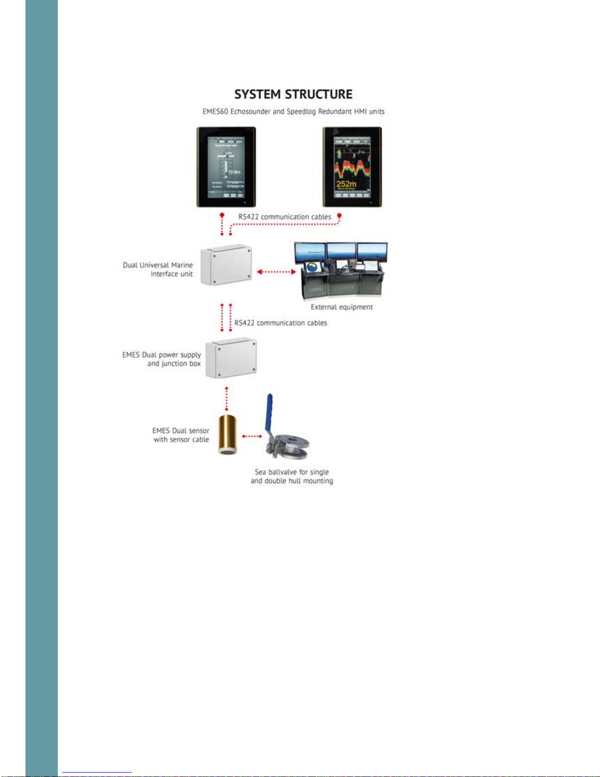
EMES60 is a combined electromagnetic speed log and echosounder navigation
system. It is a single sensor with two transducers in one housing.
Both parts have been designed to meet the relevant international standards and
provide all the modern and legacy input-output interfaces that are specified by
the IMO standards.
As required by the relevant regulations, the two parts are totally separated
internally.
The main advantage of this arrangement is that the system only needs one hull
penetration, and one set of mounting hardware, thus increasing reliability and
reducing costs of installation and maintenance.
The size and weight of the sensor is significantly less than other systems on the
market, which greatly facilitates installation and handling.
2.2 Highlights
•Only one hull penetration, which increases safety of navigation
•Small overall diameter of sensor, requiring small hull penetration, which
minimizes the risk of mechanical damage
•Sophisticated analog and digital signal processing, which provides reliable
data in any navigation conditions
•All modern and legacy input-output interfaces are supported, including
IEC61162-1
•Sound speed calibration based on temperature, which provides accurate
depth measurements in different conditions without the need for manual
adjustments
•Includes water temperature sensor, accurate to 1°C
•Optimized electromagnetic log operational parameters, which provides
accurate speed through water measurements in different water conditions,
such as sea water, river water, and brackish water
7
2.3 System Structure

8
3Operation, generic
3.1 HMI Touch-Screen Controls
Reading the speed and depth information from the system, and configuring the
system for use, is done through the touch-screen display units, called “human-
machine interface” (HMI) units.
Data is also sent to external equipment using a range of standard communication
protocols and data formats.
Two HMI Units are usually fitted, both of which can run both the echosounder and
speed log parts of the system, but typically one is configured to run the
echosounder, and the other is configured to run the speed log.
The HMI Units use touch-screen technology, so that controlling the system is done
by touching the relevant part of the HMI Unit screen.
The structure and operation of both HMI units is similar. The examples below are
from the echosounder, but the principles are the same for the speed log.
3.2 Structure of the operational screen
GNSS and THD sensors data, ref 3.3
Miscellaneous buttons, ref 3.5
Main window: different for each system and
each screen type
Settings buttons:touch to change
settings and Home access, screen
Simulation mode indicator

9
The exact contents of the parts of the screen are different for each screen type;
see the section for each screen for detailed information.
3.3 GNSS and THD sensors data
All the screens show GNSS and THD sensor data received by the system in the top
row of the screen.
This section can be enabled or disabled using the GPS Display on/off button at the
top of the Home screen.
3.4 Using the on-screen keyboard to enter data
On-screen keyboard is used to change some of
the user adjustable settings. The upper line
contains the name of the edited parameter. The
operator should enter the desired value and
press the “enter” button. Backspace button can
be used to delete the characters to the left from
the cursor. In order to cancel operation without
saving the changes – press the Esc button
or touch any area
Outside the keyboard frame.
GNSS receiver speed
Heading
Position, Northing
Position, Easting
Touch to toggle GNSS displaying
Backspace button
Enter button
Parameter name
Edit line
10
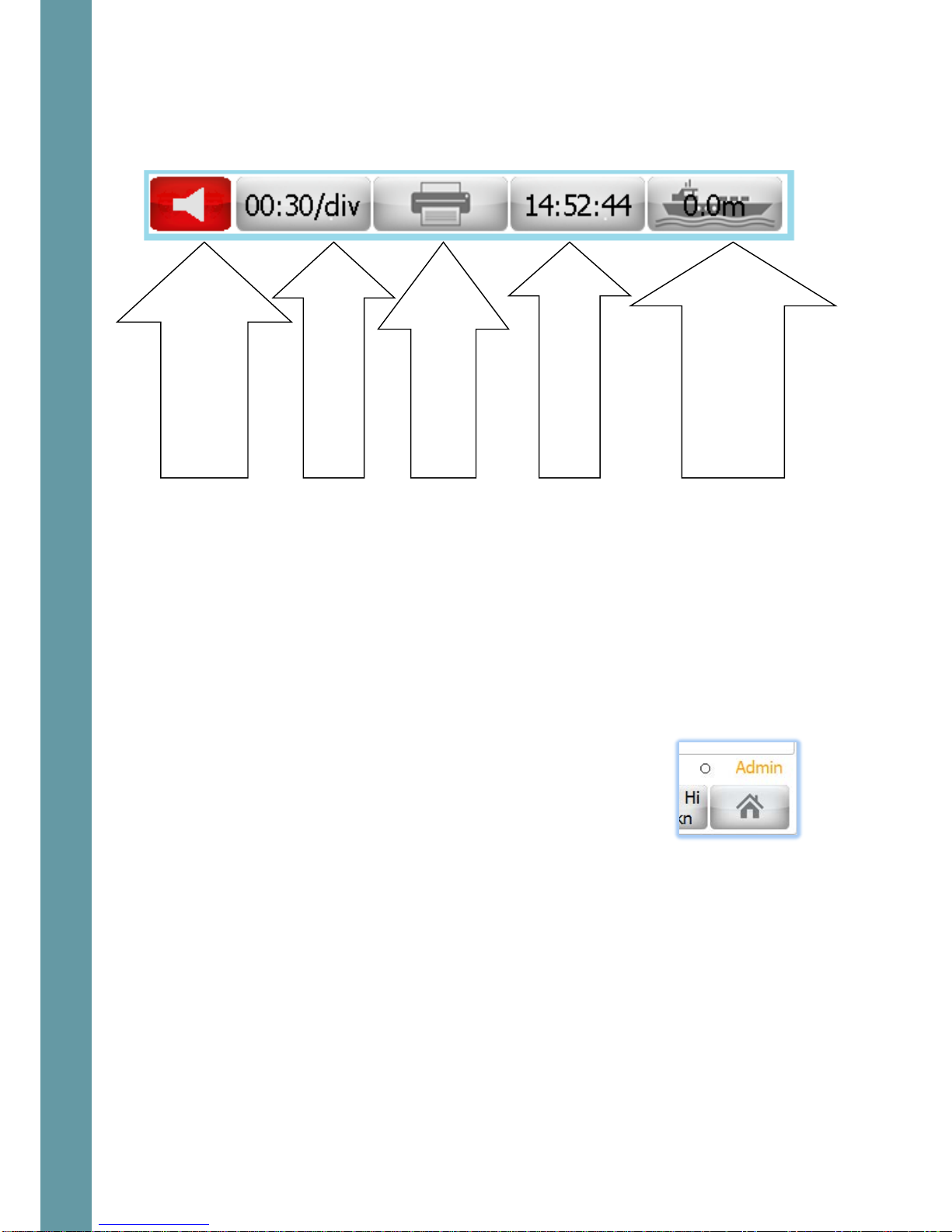
3.5 Miscellaneous buttons
The second row has a set of buttons, which provide numerical outputs as well as
controls for the system. Each screen type is slightly different, but a typical one is as
follows.
3.6 Administrator mode
EMES60 has two input modes: “Normal User” and “Administrator”.
Some operational parameters could prevent correct operation of EMES60 if they
are set incorrectly. These parameters cannot be set in Normal User mode, and the
operator must change to Administrator mode in order to get access to the setup
screens.
All setup, calibration and troubleshooting screens are accessible only in
Administrator mode.
The system starts in Normal User mode. To change to
Administrator mode, go to the Home Screen (ref 3.7), and
enter the Administrator password in the “Password” section.
The administrator password is 1963
The current input mode is shown at the bottom of the
screen.
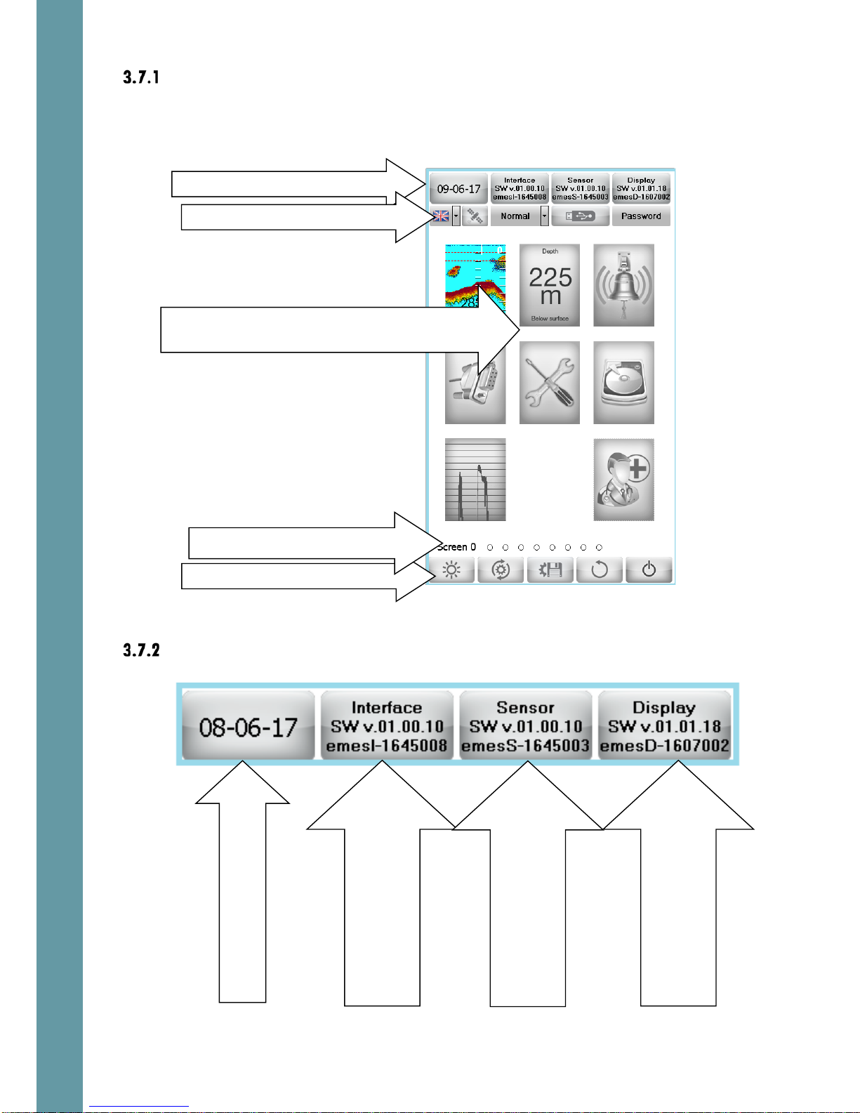
3.7 Home screen
Touch the button in the bottom-right of most screens to access the Home screen.
Window-specific control;
echogram advance
Screen dump or
continuous printing
Time display: touch to
change the time
System specific control
Draft – for echosounder,
Water temperature for
speedlog
Alarm indicator:
touch to see the list
of active alarms
11
Home screen layout
The Home screens of the Echosounder and Speed Log interfaces are similar, but a
different selection of screens is available for each.
Home screen upper line
Screen selection:touch to select an operational
screen
Home screen Control buttons
Home screen Upper line
Home screen Second line
Screens navigation
SW version and serial
number of Interface Unit.
Touch to upgrade software
Date: touch to change
SW version and serial
number of Sensor Unit.
Touch to upgrade software
SW version and serial
number of HMI(Display) Unit.
Touch to upgrade software
12
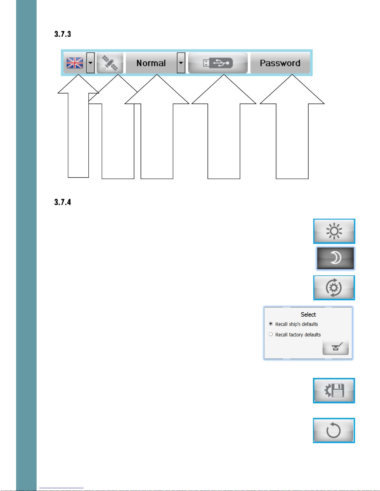
Home screen second line
Home screen Control buttons
Day/Night mode: touch to toggle between Day
and Night display modes. The button shows the
current mode. In night mode, the display is shown
in darker colors, to preserve the night vision of the
user. A sun icon is shown in Day mode, and a
moon in Night mode.
Defaults: sets the system settings to default values.
You are then presented with the option of restoring
to either the ship’s defaults (see below) or factory
defaults.
An “Are You Sure” screen appears when the tick
button is touched. Touch “OK” to return all the
settings of the system to the selected set of settings.
Store ship’s default settings: stores the current
settings of EMES60. This function is recommended
after the required setup is performed. Then it will be
easy to restore the original settings in case of
accidental in case of accidental loss of the
settings. Also see Saving Files to USB, section 7.1.
Return to Screen: returns the display to the previous
operational screen
Toggle ON/OFF GNSS and
heading indication line on
the operational screens
Language select
Toggle between
Normal/Demo/Simulation
modes ref 3.12
Activate functions related
to USB disk, ref 7.1
Enter the password – to
change the privileges
(User, Admin, and Service).

13
Standby: turns the system in Standby mode. An
“Are You Sure” screen appears when this button is
touched. Touch “OK” to turn the system in Standby
mode.
3.8 Alerts
Alerts basics
If a value goes over a minimum or maximum limit, or functional failure occurs, an
alert will be triggered. This causes the following things to happen:
•A flashing text indicator is shown in a
prominent position on the screen
•The alert state is logged to an alert list, with the time stamp of the alert status
change
•The potential free relays in the Interface Unit can be activated (depending
on the settings of each relay function, ref section 6.6.4). These can be used
to trigger audible alerts or set alerts in other systems.
To acknowledge an alert, causing the on-screen warning to disappear, touch the
flashing warning box. More than one alert condition could be in place at the same
time, so it may be necessary to repeat this procedure to acknowledge the other
alerts.
The alert parameters are adjusted, controlled and monitored using the Alert
screens, ref sections 4.4 and 5.4
The “loudspeaker” button is on provided in the
second line of each screen. The color of the
button depends on the existing alarm
conditions. If any alarm condition exists – the
button is red, otherwise – grey.
Touch the “loudspeaker” button and the active
alarms list will appear.
Alarm status can be “Active” or “Inactive”
Acknowledge status can be “A”
(Acknowledged) or “N” (Not acknowledged)
This way it is always possible to check the alarms
status after they has been acknowledged.
Generic alert conditions
There are several alert types, which are common for both echosounder and speed
log systems.

14
These are:
Void
Void
void
The alert types which are specific to one of the systems are explained in 4.4 and
5.4
Setting alert limits
The values at which alert is triggered are shown in Alert Buttons at the bottom of
the screen. There are two buttons, one for the alert when the value gets too low,
and one for when it gets too high.
To change these values, touch one of the Alert
buttons.
A digital keyboard appears on the screen; Enter
the desired value in the edit line and press “Enter”
button.
The value in the Alert button changes to show the
new selection.
3.9 Screens navigation
Use the Screens Navigation part of the screen to
go directly to a different screen: touch the dot
for the required screen.
Alternatively, “swipe” to left or right to move to an adjacent screen. The current
screen is shown as a filled dot.
IMPORTANT NOTE: Entire set of screens is available only in admin mode, ref 3.6. In
the user mode there are only basic screens (which are needed for a daily use) can
be selected.

15
3.10 Brightness control
Double-tap in any screen area, and a brightness control slider is
shown. Slide it up and down to increase and decrease the
brightness of the HMI screen.
If the brigthness is set so low that the screen picture is not visible
under the present ambient light conditons – touch any part of the
screen and keep touched for ca. 3 seconds. The brigtness will
change to a value so thee elemensts of the screen as visible in all
light conditions.
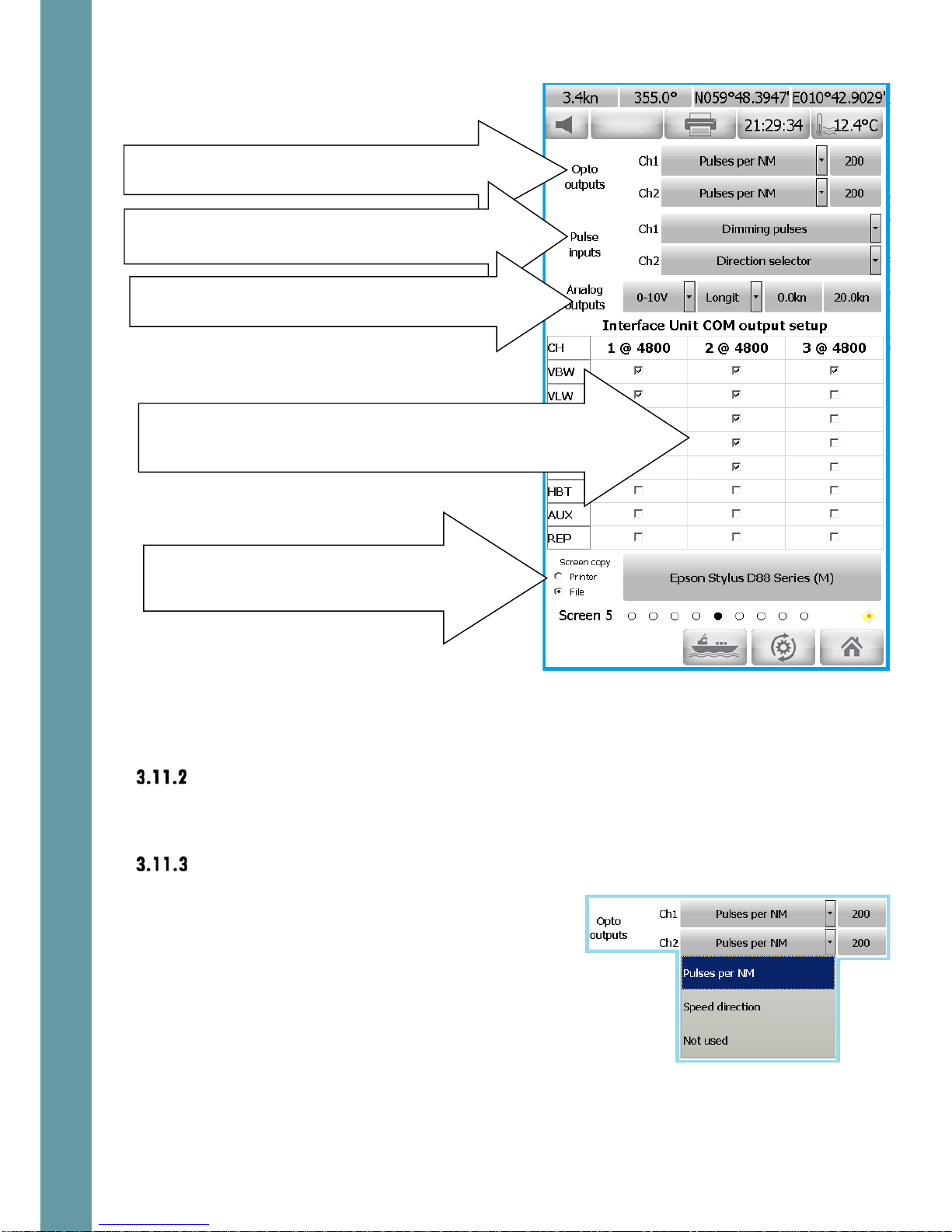
3.11 Hardware interface setup
Screen layout
This screen is used to program the Interface Unit according to the specific
requirements of the installation.
This screen can be accessed from both speed log and echosounder modes.
The default settings can be restored when necessary
Touch here to change day/night mode
16
The following outputs are available:
Relay outputs
These are controlled from the Alerts screen (ref 4.4 and 5.4)
Ref 6.5.25 for connections details.
Opto outputs
Two opto output channels are provided.
Touch the box next to each opto channel to
assign the function to this channel. Select “Not
Used” if no action is needed on that channel.
The functionality is different for speed log and
echosounder systems. Ref 4.6.7 and 5.6.7 for
further details
Factory default: Not used.
Opto outputs: touch to select the functions that drive
the Opto output channels
Pulse inputs: touch to select what happens when a
pulse is received on a pulse input channel
Analog outputs: touch to select the signals that drive
the Analog output channels
Screen copy: touch to select where screen
copy (print screen) is sent. Touch the printer
name to select the alternative
COM outputs: check/uncheck the boxes to select the messages
that are provided on the serial data output channels. Touch the
baud rate value – to set desired value
17
Pulse inputs
A signal received from an external system can
be selected to cause an action in the EMES60
system.
Two pulse input channels are provided.
The functionality is different for speed log and
echosounder systems. Ref 4.6.5 and 5.6.4 for
further details
Ref 8.2.6 for input connection details.
Factory default: Not used
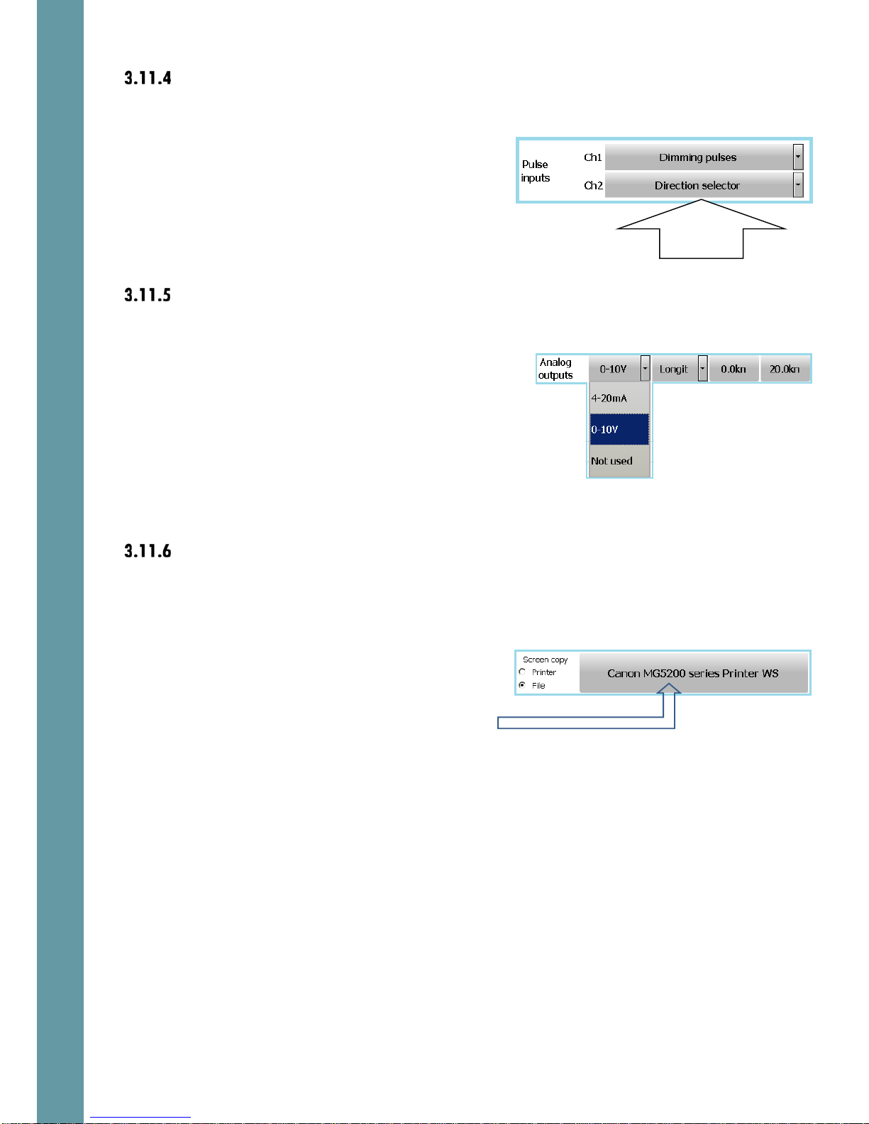
Analog outputs
Analog outputs can be configured to provide
a varying voltage output in response to a
measured value in the EMES60 system.
Two analog output channels are provided.
Touch the first box next to the channel number
to switch between 0 to 10 V voltage output and
4 to 20 mA current output.
The functionality is different for speed log and
echosounder systems. Ref 4.6.8 and 5.6.8 for
further details
Factory default: Not used
Screen copy and printing
Controls what happens when the Print Screen
button at the top of most windows is touched
Touch Printer to send screen copy images to a
printer, and File to send them to a file, stored in
the HMI memory.
Touch this box to select the printer from a list of
available system printers.
3.12 Demo and Simulation modes
EMES60 can be put into special modes, to help with training and testing.
Function
select

18
Demo and simulation modes are set in the
Home screens; touch the mode button and
select the required mode.
Warning: ensure that the mode is set to Normal
when EMES60 is used for navigation.
The available modes are:
•Normal: the information shown in the screens and the outputs from the
external interfaces are driven by the measurements made by the speed log
and echo sounder sensors.
•Demo: the screens are driven by artificial speed log and echo sounder data,
which is computed inside the EMES60 software. This mode is supposed to be
used for presentations.
•Simul: simulation mode; in this mode, the screens and outputs are also driven
by data computed by the EMES60 software, but the operator can program
the parameters of the data that is shown and output.
This is useful for training and checking the connections to the external
equipment, when real data from the sensor head is not available.
To set the simulation parameters: select simulation mode, then go back to
screen 1. Click in the area of the digital depth (or digital speed) indicator –
to change the simulated data.
Note that when either demo or simulator mode is activated the large
character S is indicated in the upper right part of all screens.
3.13 Printing and screen snapshots
Touch the Print Screen button to send data from the screen to a
printer or to the file screen for debug and maintenance
purposes.
In Echosounder mode, keep this button touched for 3 seconds
ant this this will start a continuous printout of the echogram and
the GPS position data.
The function of this button is controlled by the selection of the
Screen copy alternatives in the Hardware Interface Selection
screen (ref 3.11.6).

19
3.14 Setting the time and date
Touch the time display box to open the time-setting menu. Click
on the hours, minutes or seconds, and use the up and down
arrows to change them. Then touch the “tick box” to set the new
time.
Go to screen Home and touch the date button. Use the date
control dialog to select the required date. Then touch the “tick
box” to set the new date.
Other manuals for EMES60
2
Table of contents
Other Skipper Car Navigation System manuals


Popular Car Navigation System manuals by other brands

Lokatoo
Lokatoo A1000 Series Hardware user manual

Farenheit
Farenheit NAV-1 user manual

Garmin
Garmin nuvi 140T Series Quick start manual

Magellan
Magellan Maestro 3210 - Automotive GPS Receiver Manuel d'utilisation

Phonocar
Phonocar VM069M instruction manual

Car Solutions
Car Solutions Q-ROI-INFINITY q50 user manual


