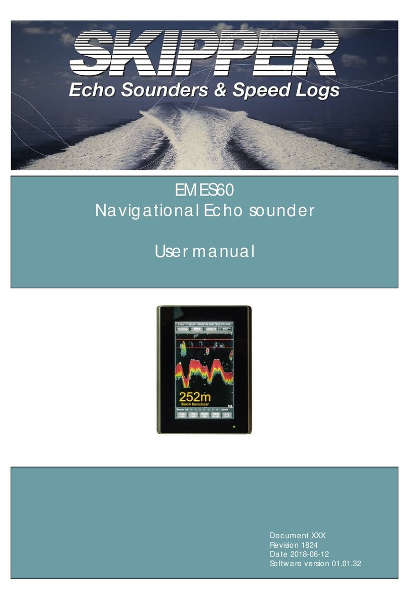
Skipper EMES60 User manual

Installation manual
Document DM-N001-SA
Revision 1824
Date 2018-06-27
Software version 01.01.32
EMES60
Navigational Echo sounder
and
Navigational STW speed log.

1
EMES60 is a combined echo sounder and speed log, providing both
speed and water depth from the same unit.
This manual gives the information necessary to install and maintain
the system.
Introduction

2
Introduction................................................................................................................................1
Table of Contents.......................................................................................................................2
1About this Manual ..............................................................................................................3
1.1 Glossary ..........................................................................................................................3
1.2 Parts of the Manual......................................................................................................4
2Introduction to EMES60.......................................................................................................5
2.1 Summary.........................................................................................................................5
2.2 Highlights........................................................................................................................5
2.3 System Structure............................................................................................................6
3Installation...........................................................................................................................7
3.1 Parts of the System .......................................................................................................7
3.2 Mounting the Sensor on the Vessel...........................................................................9
3.3 Mounting Electrical Components ...........................................................................11
3.4 Electrical Installation...................................................................................................13
3.5 Set Up the Hardware Interface................................................................................28
3.6 Calibration ...................................................................................................................29
4Maintenance.....................................................................................................................32
4.1 Saving/reading files to/from USB key and software upgrade...........................32
4.2 Precautions..................................................................................................................33
4.3 Tests and Checks........................................................................................................35
4.4 Troubleshooting...........................................................................................................38
5Technical Details ..............................................................................................................39
5.1 Circuit board layouts..................................................................................................39
5.2 Wiring Diagrams..........................................................................................................44
5.3 System Drawings.........................................................................................................47
5.4 IEC 61162-1 (NMEA 0183) Interface.........................................................................48
5.5 Data Output and Input Formats..............................................................................48
6Specifications....................................................................................................................61
Table of Contents

3
1About this Manual
1.1 Glossary
Terms used in this manual include:
DIV Division
echo sounder A device that measures the depth of water under a ship, by
measuring the time between sending a sound pulse and
receiving its echo from the seabed
electromagnetic log A type of speed log that uses electromagnetic
measurements to calculate the speed of a vessel through
water. Compare with acoustic Doppler log, which calculates
the speed through the water or relative to the seabed by
detecting shifts in frequency of acoustic echoes. EMES60 uses
an electromagnetic log.
HMI Human-machine interface: screen units that give readouts of
speed and depth, and allow the user to control and set up
the system
IMO International Maritime Organization
Interface Unit EMES60 electronic unit that connects sensor, Sensor Power
Unit and ship’s power
longitudinal speed Speed in the aft-fore direction of the vessel
opto Short for “opto-isolated”
opto-isolated An electrical input that is separated electrically from the
inputting device using an optical converter circuit
Sensor Power Unit EMES60 electronic unit that connects HMI units, external
equipment and Interface Unit
speed log A device that measures the speed of a ship relative to the
water around it and the seabed under it
TVG Time Varied Gain, signal compensation that removes
transmission loss effects from echosounder data
transducer A device that converts electrical signals to sound and back
again
transverse speed Speed in the port-starboard direction of the vessel

4
swipe technique Touch and drag – common scrolling technique applicable to
the touch screens.
1.2 Parts of the Manual
•Section 1, About this Manual, introduces this manual.
•Section 2, Introduction to EMES60, provides an overview of the system.
•Section 3, Operation, describes the day-to-day operation of the system,
including how to use the information and control screens.
•Section 5.10, Installation, gives instructions on installing the system, including
fitting the sensor unit in the hull, manual installation of the other components,
running cables between them, and setting up the system through its control
screens.
•Section 7, Maintenance, describes the maintenance procedures that are
necessary to keep the system in full working order, including the regular tests
that should be done.
•Section 8, Technical Details, provides technical details of the system,
including tables of specifications, drawings, output formats, etc.
•Section 9 provides EMES60 System Specifications.
•Section Feil! Fant ikke referansekilden., Feil! Fant ikke referansekilden., gives
more information about the company, with details of how to contact for
more information.

5
2Introduction to EMES60
2.1 Summary
EMES60 is a combined electromagnetic speed log and echosounder navigation
system. It is a single sensor with two transducers in one housing.
Both parts have been designed to meet the relevant international standards and
provide all the modern and legacy input-output interfaces that are specified by
the IMO standards.
As required by the relevant regulations, the two parts are totally separated
internally.
The main advantage of this arrangement is that the system only needs one hull
penetration, and one set of mounting hardware, thus increasing reliability and
reducing costs of installation and maintenance.
The size and weight of the sensor is significantly less than other systems on the
market, which greatly facilitates installation and handling.
2.2 Highlights
•Only one hull penetration, which increases safety of navigation
•Small overall diameter of sensor, requiring small hull penetration, which
minimizes the risk of mechanical damage
•Sophisticated analog and digital signal processing, which provides reliable
data in any navigation conditions
•All modern and legacy input-output interfaces are supported, including
IEC61162-1
•Sound speed calibration based on temperature, which provides accurate
depth measurements in different conditions without the need for manual
adjustments
•Includes water temperature sensor, accurate to 1°C
•Optimized electromagnetic log operational parameters, which provides
accurate speed through water measurements in different water conditions,
such as sea water, river water, and brackish water

6
2.3 System Structure

7
3Installation
3.1 Parts of the System
Qty
ES+
LOG
Image
HMI Units
HMI touch-screen panel 1+1
HMI panel fixings
4+4
HMI panel terminal blocks, 3pos 1+1
HMI panel Converter Board 1+1
Electronic Units and Cabling
Interface Unit cabinet 1
Interface Unit pluggable terminal
blocks, 6pos
3pos 2+2
1+1
Sensor Power Unit cabinet 1
Electronic unit fixing lugs 4+4
Sensor Power Unit pluggable ,
terminal blocks, 6pos
3pos
2+2
1+1

8
Sensor Head Assembly
The sensor are shown below. The sensor comes with 30m cable.

9
3.2 Mounting the Sensor on the Vessel
The sensor must be mounted in a water-tight valve or tank, so that the face of the
sensor is flush with the surface of the hull. This is important in order to minimize
turbulence around the sensor face.
The sensor should be mounted:
•Where there is space on the inside of the hull to access the unit for
installation and maintenance of the sensor
•On a section of the hull that is flat and horizontal, and large enough to
ensure laminar flow over the sensor face
•With the transducer face as horizontal as possible: within ±1°
•As close to the vessel’s centerline as possible
•As far forward on the vessel as possible, ideally just behind the bulbous bow,
and always in the front half of the vessel
•As deep as possible, where it remains underwater at all speeds, conditions
and vessel loadings
•Away from sources of turbulence or entrained air bubbles in all weathers,
speeds and vessel loadings. Avoid:
oBow thrusters
oObjects that protrude from the hull
•Where risk of damage, for example from anchor chains, is minimized
It may be necessary to modify the hull to provide a horizontal mounting surface. If
this is done, make sure that any welds are smoothed off to minimize turbulence.
Make sure that the direction markings on the sensor match the forward direction of
the vessel.
Before any welding:
•Remove O-rings and any parts that may be damaged by heat
After welding:
•Grind down to ensure a flush finish
Paint the fitting and hull with anti-corrosion and anti-fouling paint, but do not paint
the active surface of the sensor.

10
Installing the sensor in the valve
EMES60 is mounted in a 60mm sea valve SB-60-SA for single bottom or DB-60-SA for
double bottom. Please read sea valve installation manual for installation of sea
valve and installation of sensor in sea valve.
Cautions
•Take care not to damage the inner surfaces of the valve; do not attempt to
lift the valve by passing rope, strops or chain through the valve.
•Do not paint the surface of the sensor.
•Any modifications made to the vessel to fit the valve may require approval
of the appropriate classification body.
Removing the sensor while the vessel is afloat
The sensor can be removed from the valve while the vessel is afloat, as follows.
Caution: loosen nuts gradually, as water pressure may exert large forces on the
sensor assembly. Proceed carefully and look out for water leaks.
•Loosen the Top Nut and locking screws to free the Sensor Head Assembly.
•Lift the Installation Pipe until it stops, so that the Sensor Head is inside the Top
Flange.
•Re-tighten the Top Nut and locking screws.
•Turn the handle on the Ball Valve to close it.
•Remove the M12 nuts and washers that are holding the Top Flange to Ball
Valve.
•Carefully lift the Top Flange, with the Sensor Head inside it, from the top of
the Ball Valve.
•The Sensor Head can now be accessed by loosening the Top Nut and
locking screws and pushing on the Installation Pipe.
Preparing for dry dock
•If the vessel needs to be dry-docked again, loosen the Top Nut and locking
screws, and lift the Sensor Head by 50mm to protect its active surface.
Cathodic protection
Minimize corrosion of the sensor head by fitting a sacrificial anode.
Suitable anode types include SAF24 and SAF12 on steel hulls, and AG4 or AG4 MC
on aluminum hulls.
Regularly inspect the anode and replace it when necessary.

11
3.3 Mounting Electrical Components
The electrical components of the system are:
•Sensor Power Unit
oThis supplies power to the sensor head and communicates with the
Interface Unit.
oIt should be mounted in the forepeak, close to the sensor, where the
cable lengths are no more than 30 meters from the sensor (40 meter
cables are available on request) and no more than 600 meters from
the Interface Unit.
•Interface Unit
oThis connects the system to the HMI Units and any other external
equipment that needs the speed log or echosounder information.
oIt should be mounted in the bridge area, where the cable lengths are
no more than 600 meters from the Sensor Power Unit and no more
than 100m meters from the HMI Units and connected external
equipment.
•HMI Units
oThese provide graphical and numerical readouts of the speed and
depth information from the sensors, and allow the user to set the
control parameters of the system.
oTwo units are provided, both of which can control and monitor both
echosounder and speed log, thus providing redundancy.
oThe HMI units should be mounted in the bridge or overhead console,
where the cable lengths are no more than 100 meters from the
Interface Unit.
•External equipment
oEMES60 can be connected to external equipment, not supplied by
Northern Solutions, using standard data communications protocols
and data formats.
oThe maximum distance from the Interface Unit to the external
equipment is 500 meters.
Mounting the HMI units
The HMI units need to be mounted in a panel. Prepare a rectangular hole 138.0
mm wide and 192.0 mm high. The exterior dimensions of the unit are 149 x 202mm.
33mm depth is needed behind the panel, plus at least 20mm to allow for air
cooling and for the NMEA Converter Board.
Note that the HMI unit is used in “portrait” mode, with the long side vertical.
NMEA communications is made through an NMEA Converter Board, which
converts RS422 signals at the 9-way D-type connector on the HMI unit into NMEA
0183 signals on a screw terminal.

12
Figure 1 HMI unit dimensions
Mounting Electronic Units
Mount the electronic units with the glands facing downwards, to minimize the risk
of water ingress and ease cable routing.

13
3.4 Electrical Installation
Block Diagram
Figure 2 EMES60 Block Diagram

14
Electronic Unit Layouts
In both the Sensor Power Unit and the Interface Unit, the board handling the
echosounder is on the left, and the board handling the speed log is on the right.
Figure 3 Sensor Power Unit boards
Figure 4 Interface Unit boards

15
Cable Diagram
The cables used in the system, with their names, are shown in the diagram below.
The number of cables leading to external equipment depends on the number of
external systems that are required to be connected to EMES60. In the diagram, IU-
Ext1-* means IU-Ext1-1, IU-Ext1-2, IU-Ext1-3, etc.
Regulations require that the speed log and echosounder sides of the system must
be independent of each other, so they have separate power and
communications connection cables.
HMI 1HMI 2
Interface Unit
Sensor Power Unit
Sensor
External
equipment
External
equipment
IU-HMI1 IU-HMI2
IU-Ext1-* IU-Ext2-*
SPU-IU
SPU-Sensor
AC Power
SPU-AC-Power1
DC Power
SPU-DC-Power1
AC Power
SPU-AC-Power2
DC Power
SPU-DC-Power2
AC Power
IU-AC-Power1
DC Power
IU-DC-Power1
AC Power
IU-AC-Power2
DC Power
IU-DC-Power2
Cable Types
Name Use Construction
Supplied
By
Power1 Power from ship’s
power to EMES units
Conductor size: 2.5mm
2
Configuration: twisted pair with outer
shield.
Shield type: Overall braided with
drain wire.
Installer
Comms3 Communication
signals, 3 twisted
pairs
Conductor size: 22 to 18AWG or 0.33
to 0.78mm2(typical 0.5mm2)
Configuration: 3 twisted pairs with
individual screens and outer shield.
Shield type: Overall braided with
drain wire.
Capacitance wire to shield <
150pF/m
Installer
Comms4
Communication
signals, 4 twisted
pairs
As Comms3, but 4 twisted pairs Installer
EMESSensor
Custom EMES sensor
cable, supplied with
the system
Custom-made
In EMES60
system kit
Cable List
This table lists the cables that are used to connect up the parts of an EMES60
system.

16
Name
From
To
Cable
Max Length
SPU-
Sensor Sensor Sensor Power Unit
EMES Sensor:
Custom EMES
sensor cable,
supplied with the
system
40m provided
as standard
SPU-DC-
Pow1 Power 24VDC Sensor Power Unit, left
side Power1
SPU-AC-
Pow1 Power
110/230VAC Sensor Power Unit, left
side Power1
SPU-DC-
Pow2 Power 24VDC Sensor Power Unit,
right side Power1
SPU-AC-
Pow2 Power
110/230VAC Sensor Power Unit,
right side Power1
SPU-IU
Sensor Power
Unit Interface Unit Comms4 600m
IU-HMI1
Interface Unit
left side
HMI unit 1 Comms3 100m
IU-HMI2
Interface Unit
right side
HMI unit 2 Comms3 100m
IU-DC-
Pow1 Power 24VDC Interface Unit, left
side Power1
IU-AC-
Pow1 Power
110/230VAC Interface Unit, left side Power1
IU-DC-
Pow2 Power 24VDC Interface Unit, right
side Power1
IU-AC-
Pow2 Power
110/230VAC Interface Unit, right
side Power1
IU-Ext1-* Interface
Unit, left side
External equipment
(as many connections
as required)
Comms4 45m
IU-Ext2-* Interface
Unit, side
External equipment
(as many connections
as required)
Comms4 45m)
Avoid running communications cables close to electrically noisy systems and
cables.
Pluggable Terminal Block connectors
All cable terminations are made using pluggable terminal
block connectors.
To terminate a cable, simply strip and twist the ends, insert into
the screw terminal, and tighten the screw.
All needed connectors are supplied with the EMES60 system.

17
Connection Notes
The following instructions must be followed when connecting up the EMES60
electronic unites. Failure to do this may reduce the integrity and robustness of
navigation measurements.
•The sides (echosounder and speed log) must be isolated from each other:
do not connect any signals, grounds or power wires together.
•NMEA outputs from sensor must only be connected to correct opto-coupled
NMEA inputs.
Connecting to Electronic Unites
The EMES60 electronic unites (Sensor Power Unit and Interface Unit) are connected
to each other, other parts of the EMES60 system, and external equipment using
cables that are listed in 6.5.2. These cables are provided by the installer, except for
the sensor cable, which is provided as part of the EMES60 kit.
To connect a cable to an electronic unit:
•Cut the cable to length
•Cut back the jacket to expose the outer screen
•Expose the outer screen for the gland connection
•Keep twisted pairs together; don’t un-twist them
•Strip the insulation on each core to 7mm
•Refer to the wiring schedules in sections 6.5.9-6.5.31for each cable
•Check where the cable terminates on the boards inside the electronic unit,
and select a gland in the side of the box that minimises tail length inside the
electronic unit. This information is shown in the wiring tables below and on a
diagram fixed to the inside of the door of the electronic unit.
•Loosen the gland
•Feed the cable throughthe gland
•Ensure the outer screen of the cable is electrically terminated on the gland
(this important for EMC screening regulations)
•Separate one pluggable terminal block from a circuit board. Remove the
blocks one at a time, to help make sure that the headers go back in the
right place on the board.
•Match the numbers on the terminal blocks against block and pin numbers in
wiring tables
•locations indicated in the pin numbering tables below.
•Insert the pluggable terminal into header on board. Make sure that the
terminal goes back into the right part of the header.
•Ensure that cable core functions match the screen-print on the board.
•Seal any un-used glands.

18
SPU-Sensor Cable Wiring Schedule
Sensor Power Unit
Cable
Core Use
Board Header
Terminal
Number
Left-
Hand
Echo-
sounder
J200
Ref fig5
1
purple
Echosounder sensor out + (To sensor)
2
yellow
Echosounder sensor out - (To sensor)
3
screen
4
green
Echosounder sensor in+(From sensor)
5
white
Echosounder sensor in -(From sensor)
6
screen
7
red
Echosounder sensor power +
8
black
Echosounder sensor power -
9
screen
Right-
hand,
Speed
LOG
J200
Ref fig5
1
brown
Log sensor out +(To sensor)
2
yellow
Log sensor out -(To sensor)
3
screen
4
blue
Log sensor in +(From sensor)
5
white
Log sensor in -(From sensor)
6
screen
7
orange
Log sensor power +
8
black
Log sensor power -
9
screen
SPU-IU, echosounder Cable Wiring Schedule
Interface Unit
Sensor Power Unit
Cable
Core Use
Board Header
Terminal
Number
Board Header
Terminal
Number
Left-
hand
J500,
ref
fig6
1
Left-
hand J201,
ref fig5
4
1 a
From IU to SPU A
2
5
1 b
From IU to SPU B
3
6
1 scr
SCN
4
1
2 a
From SPU to IU A
5
2
2 b
From SP to IU A
6
3
2 scr
SCN
SPU-DC-Pow1 echosounder Cable Wiring Schedule
Power Supply
Sensor Power Unit
Cable Core Use
Board Header
Terminal
Number
24V +
Left-
hand J101, ref
fig5
1
1
24V +
24V -
2
2
24V -
Ground
None
screen
screen
SPU-AC-pow1 echosounder Cable Wiring Schedule
Power Supply
Sensor Power Unit
Cable Core Use
Board Header
Terminal
Number
AC
Left-
hand J100, ref
fig5
1
1
AC power
Ground
2
yellow/green
Ground
AC
3
2
AC power

19
SPU-IU, speed log Cable Wiring Schedule
Interface Unit
Sensor Power Unit
Cable
Core Use
Board Header
Terminal
Number
Board Header
Terminal
Number
Right-
hand
J500,
ref
fig6
1
Right-
hand J201,
ref fig5
4
1 a
From IU to SPU A
2
5
1 b
From IU to SPU B
3
6
1 scr
SCN
4
1
2 a
From SPU to IU A
5
2
2 b
From SPU IU A
6
3
2 scr
SCN
SPU-DC-pow2, speed log Cable Wiring Schedule
Power Supply
Sensor Power Unit
Cable Core Use
Board Header
Terminal
Number
24V +
Right-
hand J101,ref
fig5
1
1
24V +
24V -
2
2
24V -
Ground
None
screen
screen
SPU-AC-Pow2, speed log Cable Wiring Schedule
Power Supply
Sensor Power Unit
Cable Core Use
Board Header
Terminal
Number
AC
Right-
hand J100,
ref fig5
1
1
AC power
Ground
2
green/yellow
Ground
AC
3
2
AC power
Other manuals for EMES60
2
Table of contents
Other Skipper Car Navigation System manuals
