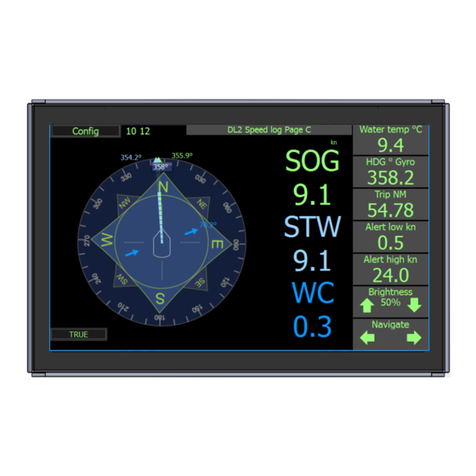
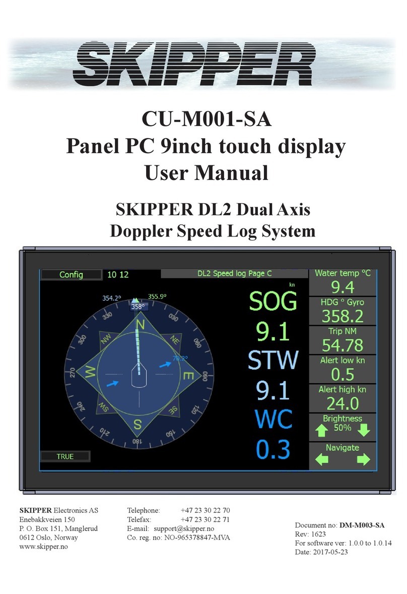
Skipper CU-M001-SB User manual

CU-M001-SA / CU-M001-SB
Panel PC 9inch touch display
User Manual
SKIPPER DL2 Dual Axis
Doppler Speed Log System
SKIPPER Electronics AS Telephone: +47 23 30 22 70
Enebakkveien 150 www.skipper.no
P. O. Box 151, Manglerud E-mail: support@skipper.no
0612 Oslo, Norway Co. reg. no: NO-965378847-MVA
Document no: DM-M003-SA
Rev: 2124
For software ver: 1.2.0
Date: 2021-06-24

Page 2 of 40 2021-06-24
CU-M001 User manual
CU-M001 PANEL PC 9” TOUCH DISPLAY. USER MANUAL
Copying of this document, and giving it to others and the use
or communication of contents thereof, are forbidden without
express authority. Oenders are liable to the payment of dam-
ages.
Sin nuestra expresa autorización, queda terminantemente
prohibida la reproducción total o parcial de este documento,
asì como su uso indebido y/o su exhibición o comunicación
a terceros. De los infractores se exigirá el correspondiente
resarcimiento de daños y perjuicios.
Weitergabe sowie vervielfältigung dieser unterlage, verwertung und mitteilung ihres
Inhaltes nicht gestattet, soweit nicht ausdrücklich zugestanden. Zuwiderhandlungen
verpichten zu schadenersatz.
Toute communication ou reproduction de ce document, toute Exploitation ou
communication de ou son contenu sont interdites, sauf autorisation expresse.
Tout manquement à cette règle est illicite et expose son auteur au versement de
dommeges et intèrèts.

2021-06-24 Page 3 of 40
CU-M001 User manual
COMMUNICATING WITH US
If you need more information, support or other assistance from us, do not hesitate to contact us:
SKIPPER Electronics AS
P. O. Box 151, Manglerud
NO-0612 Oslo
Norway
Phone: (+47) 23 30 22 70, Fax: (+47) 23 30 22 71
E-mail: support@skipper.no
SOFTWARE UPDATES AND TECHNICAL SUPPORT
Find us on the internet: www.skipper.no
YOUR FEEDBACK IS APPRECIATED
If you nd errors, misspellings or poorly explained sections in this document, please do not hesitate
to contact us at:
support@skipper.no

Page 4 of 40 2021-06-24
CU-M001 User manual
CONTENTS
TERMINOLOGY ....................................................................................................................... 5
Terms used in this manual................................................................................................................................... 5
Units .................................................................................................................................................................... 5
Abbreviations....................................................................................................................................................... 5
Symbols............................................................................................................................................................... 6
CHAPTER 1: INTRODUCTION............................................................................................... 7
DL2 Introduction .................................................................................................................................................. 7
Alarms/Alerts ....................................................................................................................................................... 8
Distance .............................................................................................................................................................. 8
The control unit.................................................................................................................................................... 8
Maintenance........................................................................................................................................................ 8
Diagnostics.......................................................................................................................................................... 8
CHAPTER 2: DL2 OPERATION.............................................................................................. 9
Run time pages ................................................................................................................................................... 9
Page A-E Navigation ........................................................................................................................................... 10
Brightness (Dimming).......................................................................................................................................... 10
Press this value (kn : NM) to change to other units............................................................................................. 11
Page A Primary Data ........................................................................................................................................... 12
Page B User selectable....................................................................................................................................... 13
Page C Resultant and direction........................................................................................................................... 14
Page D Docking .................................................................................................................................................. 15
Page E Depth ...................................................................................................................................................... 16
Page 2nd Data From DL1 (Only in DL21) ........................................................................................................... 17
CONFIGURATION MENU........................................................................................................ 20
RUNTIME SCREEN SETUP.................................................................................................... 22
CALIBRATION.......................................................................................................................... 23
Calibration Status ................................................................................................................................................ 24
Calibration. Installation angle .............................................................................................................................. 25
Calibration, Speed............................................................................................................................................... 27
Calibration, Temperature ..................................................................................................................................... 31
Calibration, Tilt..................................................................................................................................................... 31
ALERT INFORMATION ........................................................................................................... 32
Speed alerts ........................................................................................................................................................ 33
System alerts....................................................................................................................................................... 33
CHAPTER 5: DIAGNOSTICS.................................................................................................. 34
Available options in the diagnostic page ............................................................................................................. 35
CHAPTER 6: OPTIONS ON THE SYSTEM ........................................................................... 37

2021-06-24 Page 5 of 40
CU-M001 User manual
TERMINOLOGY
Terms used in this manual
_________________________________________________________
Units
Unless otherwise stated, all values shown on the display are as follows:
Speed knots
Distance (Vessel) Nautical miles
Depth Meters
Tilt ° Degrees
Temperature ° Centigrade
Rotation Degrees per minute
Heading Degrees
Abbreviations
In addition, the following abbreviations are used
WT Water track
BT Bottom track
STW Speed through water
SOG Speed over ground
TripW TripG Text for trip/total through water (W) and over ground (G)
ECDIS Electronic Chart Display and Information System
INS Inertial Navigation System
VDR Voyage Data Recorder
ROT Rotation from Gyro
GYRO Gyroscopic heading / rotation sensor
HDG Heading
DL2 2 Axis Doppler Log (with speed over bottom and Speed through water)
DL1 1 Axis speed through water sensor (part of DL21 system)
DL21 A system with combined DL1 and DL2 in the same housings

Page 6 of 40 2021-06-24
CU-M001 User manual
Symbols
In addition, the following symbols are used
Indicating that the information presented is partly from the GPS input, and therefore not
from this sensor. (outputs may show invalid data in this mode)
Symbolising that the data presented is longitudinal (forward or backwards for aft)
Symbolising the data is transversal (port or starboard)
Symbolising the resultant speed direction
Simulator Mode - The system is using a simulator to generate the speed and depth
Option - Mute Mode. The system has a sync option activated and the system is
currently being muted (No acoustics)
Symbol warning Warning/Alert Status Sound
Unrectied, unacknowledged 2 beep
Rectied, unacknowledged No beep
Unrectied, acknowledged No beep
Rectied, acknowledge (Normal) No beep
Silenced alarm No beep for 30 seconds
Responsibility transferred No beep

2021-06-24 Page 7 of 40
CU-M001 User manual
CHAPTER 1: INTRODUCTION
DL2 Introduction
The dual axis Doppler speed log system (DL2) works by the Doppler principle. This principle is that
a sound bouncing o a moving object will change in frequency. This principle can be utilized by
making a narrow beam of sound and analyzing the frequency of the returning sound. This frequency
change is proportional to the relative speed of the reecting object.
On a vessel, a transducer is positioned pointing slightly in one direction and the reected sound
comes from particles in the water (STW) and the bottom (SOG). The frequency of these echoes
is translated to speed. By having 2 transducers pointing in 90 deg directions, the speed can be
measured in two axis.
The DL2 system sends from both beams at the same time. The transducers are moulded into the
same sensor head together with the ampliers and detection circuitry (transceiver). In addition, the
sensor sends at two frequencies giving accurate values.
The sensor also contains temperature sensors and tilt sensors to allow compensation of the data.
The transceiver contains a small computer which processes the data and signals and converts them
to speeds. This data is sent to the electronic unit (JB70D2-XX) where it is formatted transferred
to the display and presented on screen , and as data in formats to be integrated into the vessels
navigation and presentation systems such as repeaters and conning.

Page 8 of 40 2021-06-24
CU-M001 User manual
Speed
The screen presents speed through water (STW) used for the autopilot, radar and logged on the
voyage data recorder (VDR). The speed data can also be used for setting limits on the rudder and
stabilizer wings. It also shows speed over ground (SOG) used as a primary system for speed. Some
of this information is also available from the GPS systems. By adding an approved gyro heading
input into the system, together with parameters of the vessel, it is possible for the system to calculate
the transversal speed at any point of the vessel. This feature known as docking, allows the pilot to
be sure that both the fore and aft of the vessel are under tight control.
Alarms/Alerts
A speed log is a “Category B” equipment with no mandatory alarms. Alarm signals from “Category
B” equipments are called alerts. Alerts can be set on the speed, usually speed through water. These
are commonly used to warn the crew if the vessel is in danger of loosing rudder steerage, or if the
vessel is going over its recommended speeds.
The DL2 display does not have an internal inbuilt audible alarm. The audible alarm must be in the
external alarm system or from an optional external alert sounder.
Distance
In addition the system shows distance travelled through water, and distance over ground and has
a resettable daily trip counter. This information is used for service intervals and navigation. Extra
information is available regarding the sea temperature and tilt of the vessel. Note. The Distance over
ground measures only when the bottom is within range.
The control unit
The user can operate the system via a touch screen or using an application on the conning unit.
The displays are intuitive and have a menu system, but also allows the user to click on the screen
to adjust the relevant parameters. Full setup, calibration and diagnostics are available from the
screens. Calibration is performed by a two leg sailing procedure, and once set, should not need
repeating unless the sensor is moved.
Maintenance
The system is low maintenance. After initial setup and calibration, the system requires no attention
except to change alert parameters if required. The sensor is exposed to the water and over time
some growth may appear. This can be carefully removed when possible, and is normally not a
problem except if the vessel is still for longer periods of time (weeks) in warm waters. The eect of
this growth is usually seen as the range of the bottom track being reduced.
Diagnostics
The system has comprehensive built in test (BIT) that can be used to analyse the performance of the
equipment and give a warning if the data is not within specication. It also has inbuilt redundancy in
some areas, such that even if a failure occurs, it can still give some data. Due to the systems LAN
network point, it is possible to set up the system for remote diagnostics and upgrade using network.
In time this will help reduce service visits and increase the probability of rst time x. Inserting a USB
stick into the electronic unit causes the system to log all the available parameters, and these les
can be sent to skipper or your service provider to diagnose errors in the system

2021-06-24 Page 9 of 40
CU-M001 User manual
CHAPTER 2: DL2 OPERATION
Run time pages
The DL2 display has 5 main runtime pages A-E, all except A can be deactivated..
Additional an optional “page 2.nd system” is available for use on DL21 systems to show STW from
DL1 part of DL21.
Page A
Basic
Page B
Combination
(Programmable)
(Optional)
Page C
Rose diagram
(Optional)
Page D
Docking
(Optional)
Page E
Depth
(Optional)
Page 2nd. system
(Optional for DL21
systems)

Page 10 of 40 2021-06-24
CU-M001 User manual
Page A-E Navigation
Pages can be changed by using the “Navigate” arrows on the lower right side of the screen.
In each of the pages A-E the main area is programmable to enable/disable required information.
Page A is not possible to disable. SOG is always on in page A.
Conguration and enabling of pages is performed in “cong” See “Runtime Screen setup”
Brightness (Dimming)
The brightness can be set from 1 to 100%.
If an unacknowledged alert is present, the screen cannot be dimmed to the lowest settings.
If the screen is dimmed too low to see. press and hold on the left of the screen, the dimming will
raise itself to default (50%)

2021-06-24 Page 11 of 40
CU-M001 User manual
Colour code:
Speed Through Water (STW) is in light blue
Speed Over Ground (SOG) is in green/yellow
Water Current (WC) is in dark blue
If the speed value is not available it will show -.- (dashed line).
SOG will be available only when the bottom is within range.(depth <150m)
If GPS and Rate of turn is connected from an external source, the speed will be shown with a
symbol, when the depth >150m, bt this will n ot be sent out of the system as this system is not the
source of the data.
Press this value (kn : NM) to
change to other units
Information 1-5
Informations can be set to the following: Water temperature / Trip / Total / Alert Hi / Alert lo / Pitch /
Roll / SOG from GPS / ROT from gyro / Heading from gyro / STW (DL1) Items that can be changed
or reset, will do so by pressing and holding the information panel (Trip/ Alert)

Page 12 of 40 2021-06-24
CU-M001 User manual
Page A Primary Data
Options:
This screen shows the primary data of the system.
The parameters shown can be selected or removed,
and the information on the side panel can be selected
The shown values are resultant values combine both
the ahead (Longitudinal) and sideways (Transvesal)
data. The angle of the movement is shown in the
symbol of a vessel with a moving arrow.
If the system is a DL21 then the information from
the DL1 can also be shown on this display as shown
above.
An option exists (in DL2 setup), to change the DL2
system tinto a SOG only system (The STW param-
eter coming from DL1 part) . In this case the STW
information will not be available except from DL1.
If selected, The GPS speed can be displayed if the
bottom tracking fails. In this case a GPS symbol will
appear next to the inuenced parameters.

2021-06-24 Page 13 of 40
CU-M001 User manual
Page B User selectable
Options:
This Screen can be used to display combinations of
data either as a vector with large arrows (as shown),
or as a resultant and direction symbol.
The Information sidebar can be programmed to
show whatever is available

Page 14 of 40 2021-06-24
CU-M001 User manual
Page C Resultant and direction
If True is selected then a compass rose will be shown on screen, if the gyro input is not present the Relative
display should be selected.
TRUE and RELATIVE can be selected by pressing the text or on the screen setup menu
Water current (WC)
The Dark blue arrow is the calculated current, this only shows direction as the current is normally small. The
arrow points in the direction the current ows (sets) This option is default o and can only be turned on if
there are a satisfactory number of calibrations (3).
If the bottom tracking of the system fails (too deep or poor signal) and a GPS input is connected, then this
display can be made to compensate the current using that signal.
Options:
This screen can show the resultant speeds of the vessel, and also the direction of the current. If a Gyro is
connected and activated, the angles will be true, if not they will be relative. The length of the vector in the
graphic to the left represents the speed. The Outer rim of the compass rose indicates maximum speed (the
speed is entered in the DL2 Menu)

2021-06-24 Page 15 of 40
CU-M001 User manual
Page D Docking
Options:
This page is designed to clearly show the speed over ground of the vessel, and is particularly useful during
docking manouvres and general manouvring.
If Gyro is connected with a valid ROT signal, the system will calculate the Aft speed based on the vessel
length measurements entered in DL2 Menu.

Page 16 of 40 2021-06-24
CU-M001 User manual
Page E Depth
Depth is measured on the two main measurement beams of the system. These are tilted at 30 degrees from
vertical and will therefore measure in front of the sensor and to the side.
As the system does not measure vertically, there is a danger that the beam will be bent (refracted) in the wa-
ter as the water temperature (and therfore sound speed) changes. This is impossible to predict, and so there
will be some error in the system particularly in deeper water.
This system is therefore not approved to be used as the primary echo sounder for the vessel.
The average value takes the forward looking beam, and calulates the depth at that point and using the meas-
ured speeds predicts when that point is vertically under the vessel
The graphic on the left shows an echogram of the depth below the vessel. This graphic is unusual in that it
uses the speed to calulate where the displayed points are relative to the vessel. If the vessel sails backawards
the plot will grow to the right, if still all the points will congregate in front of the vessel. The calculated
depth directly below the sensor is shown as the depth.
The graphic on the right shows the individual beams depths adjusted to vertical depth.
Options: There are no options on this page, pressing the depth unit (default meters) will change the unit to
feet, or fathoms.

2021-06-24 Page 17 of 40
CU-M001 User manual
Page 2nd Data From DL1 (Only in DL21)
Options:
This page may be used in the DL21 dual system
conguration. In this conguration the second DL1
Single axis system communicates internally (no ad-
ditional wiring needed) with the DL2 and allows it
to display the calibrated speeds from that system.
The Information on the sidepanel is from the this
DL2 system
The Colour background is in place to highlight that
this is secondary information. In the case of an alert
on the DL2 the system will jump back to page A

Page 18 of 40 2021-06-24
CU-M001 User manual
Loss of bottom track/open ocean
If the bottom track is lost, normally due to depth outside of the range of the vessel, the system will
put dashes into the areas with no data. If water current is selected and both GPS and heading are
input, the current will use these data for compensation. If not, this parameter will not be available.
Display of bottom track from GPS
If this function is enabled, the unit can be made to replace SOG information on screen with information
derived from GPS and heading. This information is not given out from the units communication
system, as it is not generated from this unit.(MED regulations) if GPS data is inuse for all or part of
the calculation of the displayed data, a symbol will be displayed by the eected data
Surface current measurement
Surface current is measured in the water track cell.(1-3m distance from sensor)
This cell size may vary in dierent water depth conditions, but it is shown on the depth display.
Surface current has its own separate display allowing the user to adjust some of the parameters.
Other parameters
• Temperature: is measured at the water boundary, with in the sensor, its data is used
internally to compensate for sound speed
• Tilt, is measured in the sensor, and is used internally for quality control of data
• Depth, is measured from all beams. These beams are slanted at approx. 30 degrees and
will therefore not measure directly underneath the vessel. For this reason, they cannot
be used as an approved sounder. However they cvan be ouput as a PSKPDPC NMEA
message
Trip
The trip values measure the distance travelled through water, or over the ground. The total is the
distance since system installation, the trip can be reset to show daily trip or service intervals. If
presented in an information the trip can be reset by pressing and holding the Trip information,
otherwise the trip reset can be found in the DL setup menu. Trip can also be reset remotely as
required in some standards, from SKIPPER multi-repeaters, or by NMEA command.
If presented on the main screen, the trip and total through water will show in blue, and the ground
values will show in green/yellow. Trip through water is the most meaningful in this system and is
displayed by default. Trip over ground can be selected, but will become inaccurate once the bottom
is lost, it is then displayed as yellow, for ‘low integrity’
Total
The total value is by default the total distance sailed through water (using the STW value that should
always be present) or over ground. This value cannot be reset except by qualied service personnel.
Water total is shown by default, but Ground distance total can also be selected. This will also show
as yellow once the bottom is lost and the number becomes inaccurate

2021-06-24 Page 19 of 40
CU-M001 User manual
Things that may effect performance:
The system sends acoustic beams into the water. These need reections from the bottom for SOG
and from particals in the water for STW. If the bottom is out of range then the bottom track will fail. If
there are very few particals in the water, the signal may also be weakened.
If the vessel bow is breaching the surface, so that there is air in front of the sensor, then the system
may temporarily loose the signal. Increasing the averaging will stabilise this data.
Interpretation of the IEC61023 standard can vary, and generally it is expected that the STW
parameter should be measured within 3m of the vessel. In some cases the vessel may drag water
with it, and this is compensated by calibration. This unit meausres within the rst 3 m, but if required
the sampling volume can be moved out from the vessel in the DL2 setup pages to give better results.
At low depths the system will adjust its sampling volume down to be within the water volume. This
may increase the STW noise.
Depth
Depth is calculated from the bottom track (SOG) signal. Depth from each individual beam can be
plotted on a depth plot and the average of both can also be displayed. These depths are default from
the sensor, and the draught setting must be used to make them display from the surface or from the
hull bottom. There is no calibration for this sensor, however it is important the tilt and temperature are
correct to allow the best possible correction for beam bending and soundspeed in water.

Page 20 of 40 2021-06-24
CU-M001 User manual
CONFIGURATION MENU
By pressing the Cong button on the top left, a set of conguration menus are entered.
This manual suits for next models
1
Table of contents
Other Skipper Touch Panel manuals
Popular Touch Panel manuals by other brands
Transcell Technology
Transcell Technology TI-500 RF Series user manual
EMS
EMS FireCell FCZ-170-111 Programming guide
American Lighting
American Lighting CTRLW-DMXB-TW-4Z manual
IEI Technology
IEI Technology UPC-V315-QM77 user manual

Crestron
Crestron Isys TPS-4L Operations & installation guide
Extron electronics
Extron electronics TouchLink TLP 350CV installation guide
