Skope VF Series User manual

VF Series
SKOPE Glass Door Vertical Freezer
Service Manual
MAN10522 Rev. 3.1 Jul. 2018

VF Series
SKOPE Glass Door Vertical Freezer
Service Manual
MAN10522
Rev. 3.1 Jul. 2018
© 2013 SKOPE Industries Limited. All rights reserved.
SKOPE Industries Limited reserve the right to alter specifications without notice.
is a registered trademark of SKOPE Industries Limited.
SKOPE INDUSTRIES LIMITED
Head Office
PO Box 1091, Christchurch
New Zealand
Freephone: 0800 947 5673
Fax: (03) 983 3896
E-mail: [email protected]
Website: www.skope.co.nz
Trademark Infringement
The SKOPE trademark on this product is infringed if the owner, for the time being, does
any of the following:
• Applies the trade mark to the product after their state, condition, get-up or packaging
has been altered in any manner
• Alters, removes (including part removal) or obliterates (including part obliteration) the
trade mark on the product
• Applies any other trade mark to the product
• Adds to the product any written material that is likely to damage the reputation of the
trade mark
Notice of the above contractual obligations passes to:
• Successors or assignees of the buyer
• Future owners of the product

SKOPE VF Series
Service Manual iii
CONTENTS
1 Specifications
VF650 Series . . . . . . . . . . . . . . . . . . . . . . . . . . . . . . . . . . . . . . . . . . . . . . . 5
VF1000 Series . . . . . . . . . . . . . . . . . . . . . . . . . . . . . . . . . . . . . . . . . . . . . . 6
VF1300 Series . . . . . . . . . . . . . . . . . . . . . . . . . . . . . . . . . . . . . . . . . . . . . . 7
VF1500 Series (twin unit) . . . . . . . . . . . . . . . . . . . . . . . . . . . . . . . . . . . . . 8
Servicing Tools . . . . . . . . . . . . . . . . . . . . . . . . . . . . . . . . . . . . . . . . . . . . . . . . 9
2 SKOPE CAREL ir33 Controller
Overview . . . . . . . . . . . . . . . . . . . . . . . . . . . . . . . . . . . . . . . . . . . . . . . . . . . . 10
Display . . . . . . . . . . . . . . . . . . . . . . . . . . . . . . . . . . . . . . . . . . . . . . . . . . . . . 11
Cycles . . . . . . . . . . . . . . . . . . . . . . . . . . . . . . . . . . . . . . . . . . . . . . . . . . . . . . 12
Defrost Cycle . . . . . . . . . . . . . . . . . . . . . . . . . . . . . . . . . . . . . . . . . . . . . . 12
Continuous Cycle . . . . . . . . . . . . . . . . . . . . . . . . . . . . . . . . . . . . . . . . . . 12
Temperature Probes . . . . . . . . . . . . . . . . . . . . . . . . . . . . . . . . . . . . . . . . . . . 13
Control Probe . . . . . . . . . . . . . . . . . . . . . . . . . . . . . . . . . . . . . . . . . . . . . 13
Ambient Probe . . . . . . . . . . . . . . . . . . . . . . . . . . . . . . . . . . . . . . . . . . . . . 13
Evaporator Probe . . . . . . . . . . . . . . . . . . . . . . . . . . . . . . . . . . . . . . . . . . 13
Temperature Probe Reading . . . . . . . . . . . . . . . . . . . . . . . . . . . . . . . . . . 13
Alarms . . . . . . . . . . . . . . . . . . . . . . . . . . . . . . . . . . . . . . . . . . . . . . . . . . . . . . 14
Programming. . . . . . . . . . . . . . . . . . . . . . . . . . . . . . . . . . . . . . . . . . . . . . . . . 15
Set-Point . . . . . . . . . . . . . . . . . . . . . . . . . . . . . . . . . . . . . . . . . . . . . . . . . 15
Controller Reset . . . . . . . . . . . . . . . . . . . . . . . . . . . . . . . . . . . . . . . . . . . . 16
Default Program Configuration . . . . . . . . . . . . . . . . . . . . . . . . . . . . . . . . . . . 17
BN Parameter Sets . . . . . . . . . . . . . . . . . . . . . . . . . . . . . . . . . . . . . . . . . 17
Field Adjustable Programming . . . . . . . . . . . . . . . . . . . . . . . . . . . . . . . . 17
Display Stability. . . . . . . . . . . . . . . . . . . . . . . . . . . . . . . . . . . . . . . . . . . . . . . 20
Parameters . . . . . . . . . . . . . . . . . . . . . . . . . . . . . . . . . . . . . . . . . . . . . . . . . . 20
Program 485 BN1. . . . . . . . . . . . . . . . . . . . . . . . . . . . . . . . . . . . . . . . . . . 21
Program 485 BN2. . . . . . . . . . . . . . . . . . . . . . . . . . . . . . . . . . . . . . . . . . . 23
Program 485 BN3. . . . . . . . . . . . . . . . . . . . . . . . . . . . . . . . . . . . . . . . . . . 25
3 Wiring
VF Series Single Unit (EBM fan motors) . . . . . . . . . . . . . . . . . . . . . . . . . 28
VF Series Twin Unit (EBM fan motors) . . . . . . . . . . . . . . . . . . . . . . . . . . 29
VF Series Single Unit (UNADA fan motors) . . . . . . . . . . . . . . . . . . . . . . . 30
VF Series Twin Unit (UNADA fan motors) . . . . . . . . . . . . . . . . . . . . . . . . 31
4 Spare Parts
VF650 Series Cabinet Assembly. . . . . . . . . . . . . . . . . . . . . . . . . . . . . . . . . . 32
VF1000 Series Cabinet Assembly. . . . . . . . . . . . . . . . . . . . . . . . . . . . . . . . . 34
VF1300 Series Cabinet Assembly. . . . . . . . . . . . . . . . . . . . . . . . . . . . . . . . . 36
VF1500 Series Cabinet Assembly. . . . . . . . . . . . . . . . . . . . . . . . . . . . . . . . . 38
VF650 Series Side Light Assembly . . . . . . . . . . . . . . . . . . . . . . . . . . . . . . . . 40
VF1000/1300/1500 Series Centre Pillar Assembly . . . . . . . . . . . . . . . . . . . . 41
VF Glass Door Assembly . . . . . . . . . . . . . . . . . . . . . . . . . . . . . . . . . . . . . . . 42
VF Solid Door Assembly . . . . . . . . . . . . . . . . . . . . . . . . . . . . . . . . . . . . . . . . 43
Lit Sign Assembly (optional) . . . . . . . . . . . . . . . . . . . . . . . . . . . . . . . . . . . . . 44
Electronic Controller Assembly . . . . . . . . . . . . . . . . . . . . . . . . . . . . . . . . . . . 45
Unit Junction Box Assembly . . . . . . . . . . . . . . . . . . . . . . . . . . . . . . . . . . . . . 46
Unit Assembly - UF40AAD-485ZD (VF650/1500) . . . . . . . . . . . . . . . . . . . . . 47
Unit Assembly - UF50AAD-485ZD (VF1000/1300) . . . . . . . . . . . . . . . . . . . . 48
Unit Assembly - UF30AAD-485ZD (VF1300) . . . . . . . . . . . . . . . . . . . . . . . . 49

SKOPE VF Series
Service Manual
iv
5 Positioning
Positioning the Cabinet. . . . . . . . . . . . . . . . . . . . . . . . . . . . . . . . . . . . . . . . . 50
Power Cord . . . . . . . . . . . . . . . . . . . . . . . . . . . . . . . . . . . . . . . . . . . . . . . 50
Freezer Location. . . . . . . . . . . . . . . . . . . . . . . . . . . . . . . . . . . . . . . . . . . . . . 50
Ventilation . . . . . . . . . . . . . . . . . . . . . . . . . . . . . . . . . . . . . . . . . . . . . . . . 50
Shelves . . . . . . . . . . . . . . . . . . . . . . . . . . . . . . . . . . . . . . . . . . . . . . . . . . . . . 51
6 Operation
Optional Door Lock . . . . . . . . . . . . . . . . . . . . . . . . . . . . . . . . . . . . . . . . . . . . 52
Loading Product . . . . . . . . . . . . . . . . . . . . . . . . . . . . . . . . . . . . . . . . . . . . . . 52
Light Switch . . . . . . . . . . . . . . . . . . . . . . . . . . . . . . . . . . . . . . . . . . . . . . . . . 52
7 Replacement Procedures
Sign Assembly . . . . . . . . . . . . . . . . . . . . . . . . . . . . . . . . . . . . . . . . . . . . . . . 53
Lighting . . . . . . . . . . . . . . . . . . . . . . . . . . . . . . . . . . . . . . . . . . . . . . . . . . . . . 54
Interior Light . . . . . . . . . . . . . . . . . . . . . . . . . . . . . . . . . . . . . . . . . . . . . . 54
Sign Light . . . . . . . . . . . . . . . . . . . . . . . . . . . . . . . . . . . . . . . . . . . . . . . . 54
Doors . . . . . . . . . . . . . . . . . . . . . . . . . . . . . . . . . . . . . . . . . . . . . . . . . . . . . . 56
Alignment . . . . . . . . . . . . . . . . . . . . . . . . . . . . . . . . . . . . . . . . . . . . . . . . 56
Gasket Replacement . . . . . . . . . . . . . . . . . . . . . . . . . . . . . . . . . . . . . . . . 56
Tension Adjustment . . . . . . . . . . . . . . . . . . . . . . . . . . . . . . . . . . . . . . . . 57
Torsion Bar Replacement . . . . . . . . . . . . . . . . . . . . . . . . . . . . . . . . . . . . 57
Removal and Refitting . . . . . . . . . . . . . . . . . . . . . . . . . . . . . . . . . . . . . . . 58
Hinge Reversal . . . . . . . . . . . . . . . . . . . . . . . . . . . . . . . . . . . . . . . . . . . . 59
Cabinet Electrics. . . . . . . . . . . . . . . . . . . . . . . . . . . . . . . . . . . . . . . . . . . . . . 60
Control Panel . . . . . . . . . . . . . . . . . . . . . . . . . . . . . . . . . . . . . . . . . . . . . 60
Cabinet Fuses . . . . . . . . . . . . . . . . . . . . . . . . . . . . . . . . . . . . . . . . . . . . . 60
Refrigeration Unit. . . . . . . . . . . . . . . . . . . . . . . . . . . . . . . . . . . . . . . . . . . . . 61
Introduction . . . . . . . . . . . . . . . . . . . . . . . . . . . . . . . . . . . . . . . . . . . . . . . 61
Refrigeration Unit Assembly . . . . . . . . . . . . . . . . . . . . . . . . . . . . . . . . . . 62
Removing the Refrigeration Unit . . . . . . . . . . . . . . . . . . . . . . . . . . . . . . . 63
High Pressure Switch . . . . . . . . . . . . . . . . . . . . . . . . . . . . . . . . . . . . . . . 65
Unit Junction Box . . . . . . . . . . . . . . . . . . . . . . . . . . . . . . . . . . . . . . . . . . 66
Condenser Fan . . . . . . . . . . . . . . . . . . . . . . . . . . . . . . . . . . . . . . . . . . . . 67
Evaporator Fan . . . . . . . . . . . . . . . . . . . . . . . . . . . . . . . . . . . . . . . . . . . . 69
Compressor Electrics . . . . . . . . . . . . . . . . . . . . . . . . . . . . . . . . . . . . . . . 71
Compressor . . . . . . . . . . . . . . . . . . . . . . . . . . . . . . . . . . . . . . . . . . . . . . . 71
Defrost Elements . . . . . . . . . . . . . . . . . . . . . . . . . . . . . . . . . . . . . . . . . . . 72
Sump Element . . . . . . . . . . . . . . . . . . . . . . . . . . . . . . . . . . . . . . . . . . . . . 72
Electronic Controller . . . . . . . . . . . . . . . . . . . . . . . . . . . . . . . . . . . . . . . . . . . 73
Diagnostics . . . . . . . . . . . . . . . . . . . . . . . . . . . . . . . . . . . . . . . . . . . . . . . 73
Controller Wiring . . . . . . . . . . . . . . . . . . . . . . . . . . . . . . . . . . . . . . . . . . . 73
Ambient Probe Alarms . . . . . . . . . . . . . . . . . . . . . . . . . . . . . . . . . . . . . . 73
Probe Resistance . . . . . . . . . . . . . . . . . . . . . . . . . . . . . . . . . . . . . . . . . . 74
Control Probe . . . . . . . . . . . . . . . . . . . . . . . . . . . . . . . . . . . . . . . . . . . . . 75
Ambient Probe . . . . . . . . . . . . . . . . . . . . . . . . . . . . . . . . . . . . . . . . . . . . 76
Evaporator Probe . . . . . . . . . . . . . . . . . . . . . . . . . . . . . . . . . . . . . . . . . . 77
8 Maintenance
Cleaning . . . . . . . . . . . . . . . . . . . . . . . . . . . . . . . . . . . . . . . . . . . . . . . . . . . . 79
Cabinet . . . . . . . . . . . . . . . . . . . . . . . . . . . . . . . . . . . . . . . . . . . . . . . . . . 79
Condenser Coil . . . . . . . . . . . . . . . . . . . . . . . . . . . . . . . . . . . . . . . . . . . . 79
9 Troubleshooting
Diagnostic Table . . . . . . . . . . . . . . . . . . . . . . . . . . . . . . . . . . . . . 80

5
SKOPE VF Series
Specifications
Service Manual
1Specifications
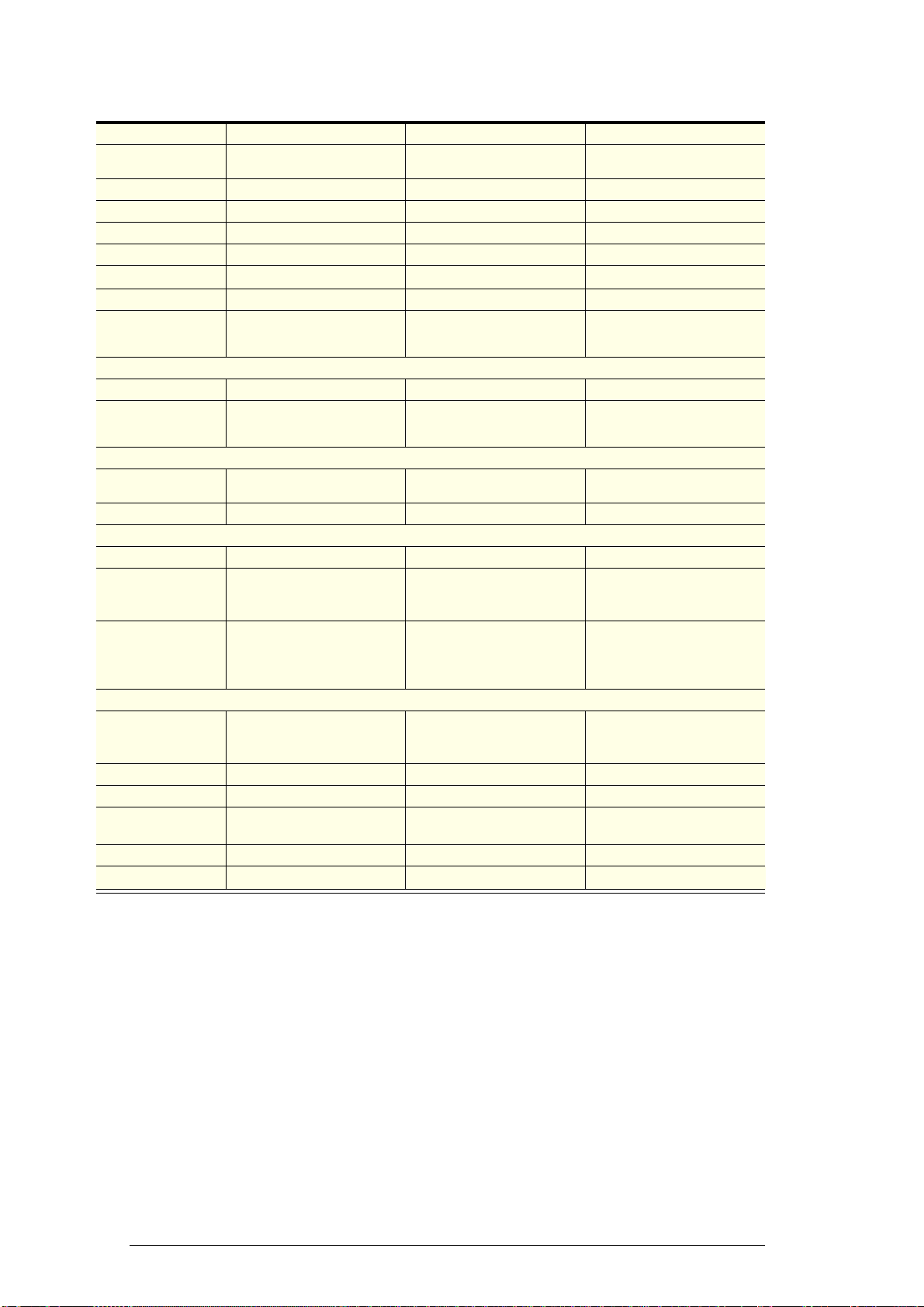
VF650 Series
VF650 VF650GP VF650-ICE
Description Glass door integral freezer Solid door integral freezer Glass door integral ice storage
cabinet
Dimensions External Internal External Internal External Internal
Height: 2195mm 1570mm 2195mm 1570mm 2195mm 1570mm
Width: 740mm 640mm 740mm 640mm 740mm 640mm
Depth: 710mm 555mm 710mm 555mm 710mm 555mm
Floor area: 0.53m20.53m20.53m2
Internal volume: 610 litres 610 litres 610 litres
Shelves: 5 × adjustable height wire
shelves: 620mm wide × 475mm
deep
5 × adjustable height wire
shelves: 620mm wide × 475mm
deep
1 × heavy duty ice shelf:
619mm wide × 475mm deep
Construction
Insulation: 50mm polyurethane foam 50mm polyurethane foam 50mm polyurethane foam
Doors: 1 × self-closing, triple glazed,
heated, toughened safety glass
swing door
1 × self-closing, solid foam
filled, swing door
1 × self-closing, triple glazed,
heated, toughened safety glass
swing door
Operating conditions
Maximum operating
temp:
40°C (Climatic Class 5) 40°C (Climatic Class 5) 32°C (Climatic Class 5)
Cabinet temp range: -18°C to -21°C -18°C to -21°C -9°C to -12°C
Electrical
Current draw: 7.5 Amps 7.5 Amps 7.5 Amps
Internal lighting: 1 × side light: 22 Watt T8 LED
tube (Ø26 × 1500mm)
1 × side light: 22 Watt T8 LED
tube (door switched) (Ø26 ×
1500mm)
1 × side light: 22 Watt T8 LED
tube (Ø26 × 1500mm)
Sign lighting: Not as standard. Optional
vented lit sign panel: 1 × 9 Watt
T8 Frosted LED tube (Ø26 ×
600mm)
Not as standard. Optional
vented lit sign panel: 1 × 9 Watt
T8 Frosted LED tube (Ø26 ×
600mm)
Not as standard. Optional
vented lit sign panel: 1 × 9 Watt
T8 Frosted LED tube (Ø26 ×
600mm)
Refrigeration unit
Description: Top mounted SKOPE Cyclone
freezer unit with electronic
controller
Top mounted SKOPE Cyclone
freezer unit with electronic
controller
Top mounted SKOPE Cyclone
freezer unit with electronic
controller
Unit model: UF40AAD-485ZD (BN1) UF40AAD-485ZD (BN2) UF40AAD-485ZD (BN3)
Compressor: DANFOSS GS26CLX DANFOSS GS26CLX DANFOSS GS26CLX
Nominal capacity: 752 Watts @ -30°C evaporator,
50°C condenser
752 Watts @ -30°C evaporator,
50°C condenser
1303 Watts @ -20°C
evaporator, 50°C condenser
Refrigerant: R404A / 700 g R404A / 700 g R404A / 700 g
Electronic controller: SKOPE CAREL ir33 SKOPE CAREL ir33 SKOPE CAREL ir33
6Specifications
Service Manual
SKOPE VF Series
VF1000 Series
VF1000 VF1000GP VF1000-ICE
Description Glass door integral freezer Solid door integral freezer Glass door integral ice storage
cabinet
Dimensions External Internal External Internal External Internal
Height: 2195mm 1570mm 2195mm 1570mm 2195mm 1570mm
Width: 1130mm 1030mm 1130mm 1030mm 1130mm 1030mm
Depth: 710mm 555mm 710mm 555mm 710mm 555mm
Floor area: 0.80m20.80m20.80m2
Internal volume: 980 litres 980 litres 980 litres
Shelves: 5 × adjustable height wire
shelves: 1009mm wide ×
460mm deep
5 × adjustable height wire
shelves: 1009mm wide ×
460mm deep
1 × heavy duty ice shelf:
1009mm wide × 460 deep
Construction
Insulation: 50mm polyurethane foam 50mm polyurethane foam 50mm polyurethane foam
Doors: 2 × self-closing, triple glazed,
heated, toughened safety glass
swing doors
2 × self-closing, solid foam
filled, swing doors
2 × self-closing, triple glazed,
heated, toughened safety glass
swing doors
Operating conditions
Maximum operating
temp:
40°C (Climatic Class 5) 40°C (Climatic Class 5) 32°C (Climatic Class 5)
Cabinet temp range: -18°C to -21°C -18°C to -21°C -9°C to -12°C
Electrical
Current draw: 9 Amps 9 Amps 9 Amps
Internal lighting: 1 × centre pillar light: Twin 24
Watt T8 LED tube (Ø26 ×
1500mm)
1 × centre pillar light: Twin 24
Watt T8 LED tube (door
switched) (Ø26 × 1500mm)
1 × centre pillar light: Twin 24
Watt T8 LED tube (Ø26 ×
1500mm)
Sign lighting: Not as standard. Optional
vented lit sign panel: 1 × 12
Watt T8 Frosted LED
tube (Ø26 × 900mm)
Not as standard. Optional
vented lit sign panel: 1 × 12
Watt T8 Frosted LED
tube (Ø26 × 900mm)
Not as standard. Optional
vented lit sign panel: 1 × 12
Watt T8 Frosted LED
tube (Ø26 × 900mm)
Refrigeration unit
Description: Top mounted SKOPE Cyclone
freezer unit with electronic
controller
Top mounted SKOPE Cyclone
freezer unit with electronic
controller
Top mounted SKOPE Cyclone
freezer unit with electronic
controller
Unit model: UF50AAD-485ZD (BN1) UF50AAD-485ZD (BN2) UF50AAD-485ZD (BN3)
Compressor: DANFOSS GS34CLX DANFOSS GS34CLX DANFOSS GS34CLX
Nominal capacity: 1097 Watts @ -30°C
evaporator, 50°C condenser
1097 Watts @ -30°C
evaporator, 50°C condenser
1846 Watts @ -20°C
evaporator, 50°C condenser
Refrigerant: R404A / 1150 g R404A / 1150 g R404A / 1150 g
Electronic controller: SKOPE CAREL ir33 SKOPE CAREL ir33 SKOPE CAREL ir33
7
SKOPE VF Series
Specifications
Service Manual
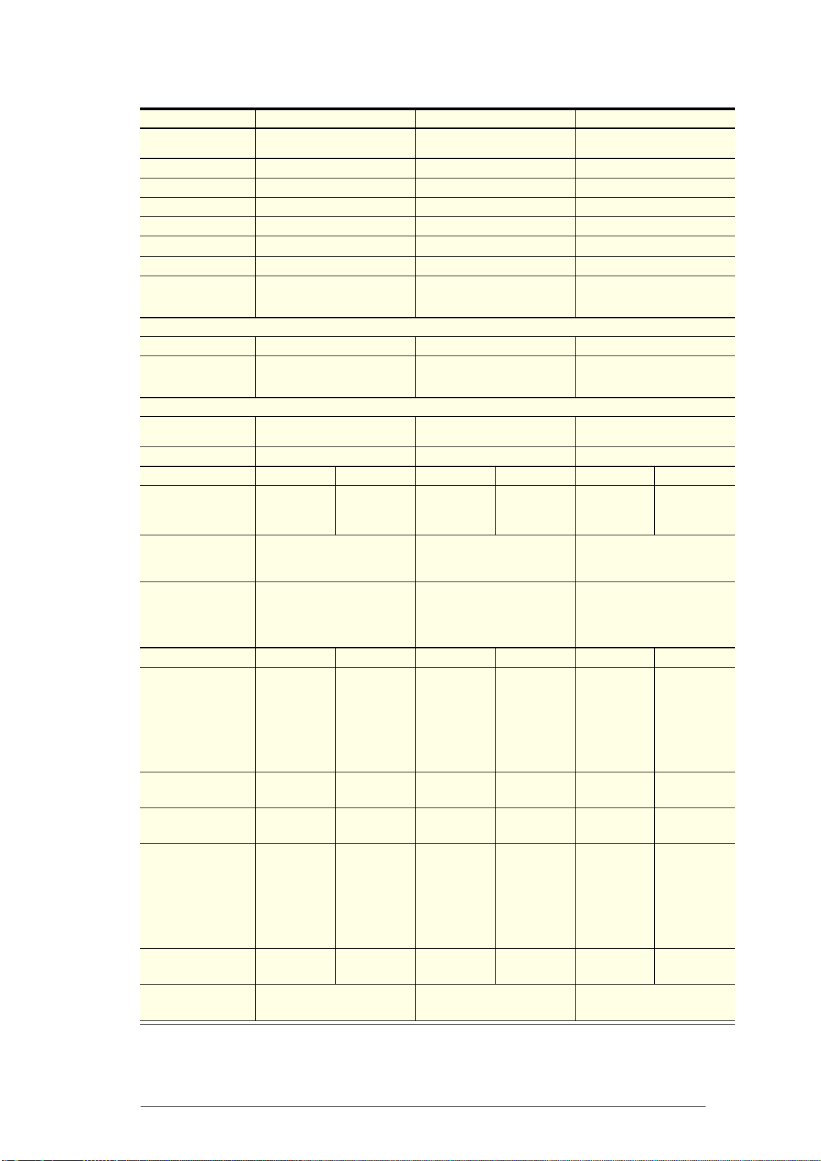
VF1300 Series
VF1300 VF1300GP VF1300-ICE
Description Glass door integral freezer Solid door integral freezer Glass door integral ice storage
cabinet
Dimensions External Internal External Internal External Internal
Height: 2195mm 1570mm 2195mm 1570mm 2195mm 1570mm
Width: 1480mm 1380mm 1480mm 1380mm 1480mm 1380mm
Depth: 710mm 555mm 710mm 555mm 710mm 555mm
Floor area: 1.05m21.05m21.05m2
Internal volume: 1310 litres 1310 litres 1310 litres
Shelves: 10 × adjustable height wire
shelves: 677mm wide × 460mm
deep
10 × adjustable height wire
shelves: 677mm wide × 460mm
deep
2 × heavy duty ice shelves:
677mm wide × 460mm deep
Construction
Insulation: 50mm polyurethane foam 50mm polyurethane foam 50mm polyurethane foam
Doors: 2 × self-closing, triple glazed,
heated, toughened safety glass
swing doors
2 × self-closing, solid foam
filled, swing doors
2 × self-closing, triple glazed,
heated, toughened safety glass
swing doors
Operating conditions
Maximum operating
temp:
40°C (Climatic Class 5) 40°C (Climatic Class 5) 32°C (Climatic Class 5)
Cabinet temp range: -18°C to -21°C -18°C to -21°C -9°C to -12°C
Electrical Single unit Twin unit Single unit Twin unit Single unit Twin unit
Current draw: 9 Amps Total 10.68
Amps (2 × 10A
plugs)
9 Amps Total 10.68
Amps (2 × 10A
plugs)
9 Amps Total 10.68
Amps (2 × 10A
plugs)
Internal lighting: 1 × centre pillar light: Twin 24
Watt T8 LED tube (Ø26 ×
1500mm)
1 × centre pillar light: Twin 24
Watt T8 LED tube (door
switched) (Ø26 × 1500mm)
1 × centre pillar light: Twin 24
Watt T8 LED tube (Ø26 ×
1500mm)
Sign lighting: Not as standard. Optional
vented lit sign panel: 1 × 20
Watt T8 Frosted LED tube (Ø26
× 1200mm)
Not as standard. Optional
vented lit sign panel: 1 × 20
Watt T8 Frosted LED tube (Ø26
× 1200mm)
Not as standard. Optional
vented lit sign panel: 1 × 20
Watt T8 Frosted LED tube (Ø26
× 1200mm)
Refrigeration unit Single unit Twin unit Single unit Twin unit Single unit Twin unit
Description: Top mounted
SKOPE
Cyclone
freezer unit
with electronic
controller
2 × top
mounted
SKOPE
Cyclone
freezer units
with electronic
controllers
Top mounted
SKOPE
Cyclone
freezer unit
with electronic
controller
2 × top
mounted
SKOPE
Cyclone
freezer units
with electronic
controllers
Top mounted
SKOPE
Cyclone
freezer unit
with electronic
controller
2 × top
mounted
SKOPE
Cyclone
freezer units
with electronic
controllers
Unit model: UF50AAD-
485ZD (BN1)
UF30AAD-
485ZD (BN1)
UF50AAD-
485ZD (BN2)
UF30AAD-
485ZD (BN2)
UF50AAD-
485ZD (BN3)
UF30AAD-
485ZD (BN3)
Compressor: DANFOSS
GS34CLX
DANFOSS
SC18CLX.2
DANFOSS
GS34CLX
DANFOSS
SC18CLX.2
DANFOSS
GS34CLX
DANFOSS
SC18CLX.2
Nominal capacity: 1097 Watts @
-30°C
evaporator,
50°C
condenser
1036 Watts (2
× 518 Watts)
@
-30°C
evaporator,
50°C
condenser
1097 Watts @
-30°C
evaporator,
50°C
condenser
1036 Watts (2
× 518 Watts)
@
-30°C
evaporator,
50°C
condenser
1846 Watts @
-20°C
evaporator,
50°C
condenser
1776 Watts (2
× 888 Watts)
@
-20°C
evaporator,
50°C
condenser
Refrigerant: R404A / 1150g R404A / 650g
(×2)
R404A / 1150g R404A / 650g
(×2)
R404A / 1150g R404A / 650g
(×2)
Electronic controller: SKOPE CAREL ir33 (1 per
freezer unit)
SKOPE CAREL ir33 (1 per
freezer unit)
SKOPE CAREL ir33 (1 per
freezer unit)
8Specifications
Service Manual
SKOPE VF Series
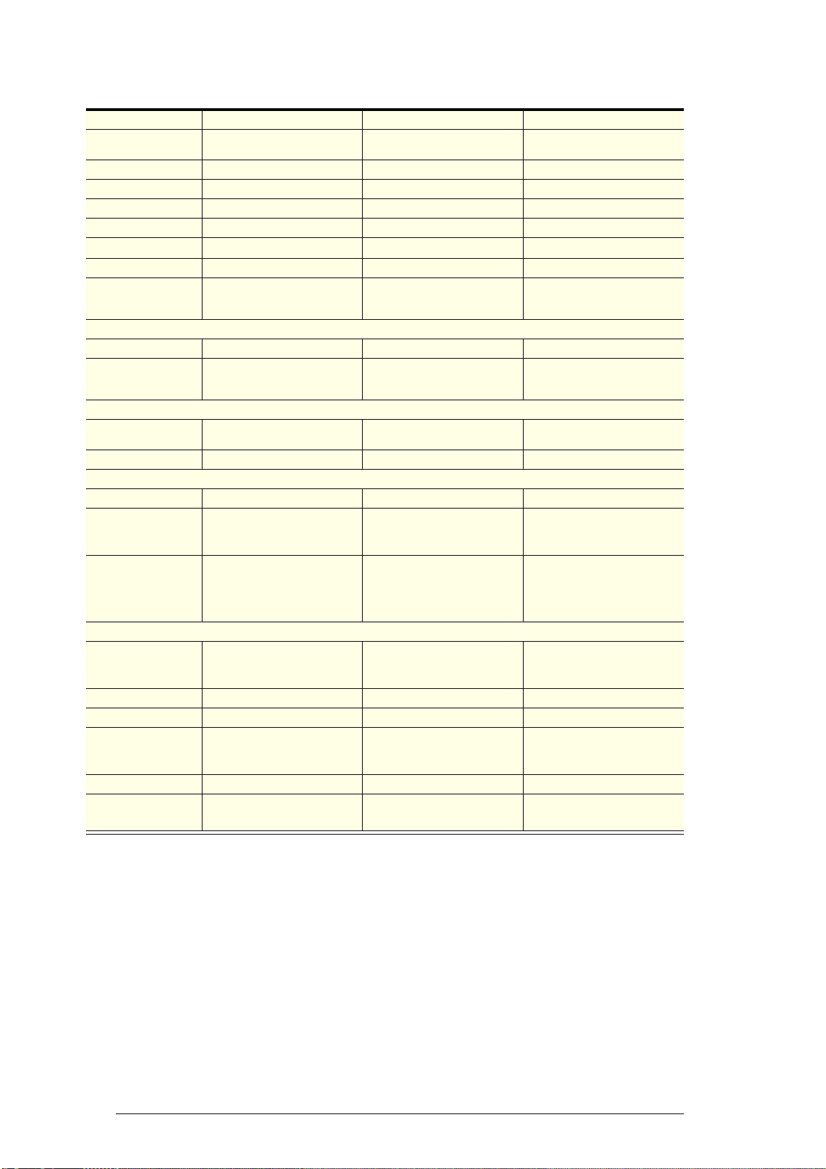
VF1500 Series (twin unit)
VF1500 VF1500GP VF1500-ICE
Description Glass door integral freezer Solid door integral freezer Glass door integral ice storage
cabinet
Dimensions External Internal External Internal External Internal
Height: 2195mm 1570mm 2195mm 1570mm 2195mm 1570mm
Width: 1706mm 1606mm 1706mm 1606mm 1706mm 1606mm
Depth: 710mm 555mm 710mm 555mm 710mm 555mm
Floor area: 1.21m21.21m21.21m2
Internal volume: 1500 litres 1500 litres 1500 litres
Shelves: 15 × adjustable height wire
shelves: 502mm wide × 460mm
deep
15 × adjustable height wire
shelves: 502mm wide × 460mm
deep
3 × heavy duty ice shelves:
502mm wide × 460mm deep
Construction
Insulation: 50mm polyurethane foam 50mm polyurethane foam 50mm polyurethane foam
Doors: 3 × self-closing, triple glazed,
heated, toughened safety glass
swing doors
3 × self-closing, solid foam
filled, swing doors
3 × self-closing, triple glazed,
heated, toughened safety glass
swing doors
Operating conditions
Maximum operating
temp:
40°C (Climatic Class 5) 40°C (Climatic Class 5) 32°C (Climatic Class 5)
Cabinet temp range: -18°C to -21°C -18°C to -21°C -9°C to -12°C
Electrical
Current draw: Total 14 Amps (2 × 10A plugs) Total 14 Amps (2 × 10A plugs) Total 14 Amps (2 × 10A plugs)
Internal lighting: 2 × centre pillar light: Twin 24
Watt T8 LED tube (Ø26 ×
1500mm)
2 × centre pillar light: Twin 24
Watt T8 LED tube (door
switched) (Ø26 × 1500mm)
2 × centre pillar light: Twin 24
Watt T8 LED tube (Ø26 ×
1500mm)
Sign lighting: Not as standard. Optional
vented lit sign panel: 1 × 22
Watt T8 LED tube
(Ø26 × 1500mm)
Not as standard. Optional
vented lit sign panel: 1 × 22
Watt T8 LED tube
(Ø26 × 1500mm)
Not as standard. Optional
vented lit sign panel: 1 × 22
Watt T8 LED tube
(Ø26 × 1500mm)
Refrigeration unit
Description: 2 × top mounted SKOPE
Cyclone freezer units with
electronic controllers
2 × top mounted SKOPE
Cyclone freezer units with
electronic controllers
2 × top mounted SKOPE
Cyclone freezer units with
electronic controllers
Unit model: UF40AAD-485ZD (BN1) UF40AAD-485ZD (BN2) UF40AAD-485ZD (BN3)
Compressor: DANFOSS GS26CLX DANFOSS GS26CLX DANFOSS GS26CLX
Nominal capacity: 1504 Watts (2 × 752 Watts) @
-30°C evaporator, 50°C
condenser
1504 Watts (2 × 752 Watts) @
-30°C evaporator, 50°C
condenser
2606 Watts (2 × 1303 Watts) @
-20°C evaporator, 50°C
condenser
Refrigerant: R404A / 700 g (×2) R404A / 700 g (×2) R404A / 700 g (×2)
Electronic controller: SKOPE CAREL ir33 (1 per
freezer unit)
SKOPE CAREL ir33 (1 per
freezer unit)
SKOPE CAREL ir33 (1 per
freezer unit)

9
SKOPE VF Series
Specifications
Service Manual
Servicing Tools Tools required for servicing may consist of the following:
Screwdriver with Pozidriv PZ1 and PZ2 bit
Slotted screwdriver
Small slotted screwdriver (for electrical connectors)

10 SKOPE CAREL ir33 Controller
Service Manual
SKOPE VF Series
2SKOPE CAREL ir33 Controller
Overview
The SKOPE electronic controller controls and displays the cabinet
temperature. The preset temperature setting controls internal air
temperature between -21°C and -18°C in integral freezers, and between
-12°C and -9°C in ice storage cabinets.
The electronic controller also signals temperature alarms, recording the
minimum and maximum value reached at the time of the alarm.
To ensure efficient operation, the electronic controller has a built in minimum
off cycle time of 5 minutes and features regular temperature terminated
defrost cycles. During the defrost cycle the compressor and evaporator fan
switch off.
The SKOPE electronic controller is a unique SKOPE customised Carel ir33
controller. This custom controller cannot be interchanged with a standard
Carel ir33 controller.
VF Series electronic controllers are pre-loaded with three different
parameter sets (BN1, BN2 and BN3) for use with VF Series cabinet
variations. Refer to “Parameters” on page 20 for more information.
Description Manufacturer part No. SKOPE part No.
SKOPE Carel ir33
Electronic Controller IRSKC0HF325 ELZ3333AP-485
Figure 1: SKOPE Carel
ir33 electronic controller
11
SKOPE VF Series
SKOPE CAREL ir33 Controller
Service Manual
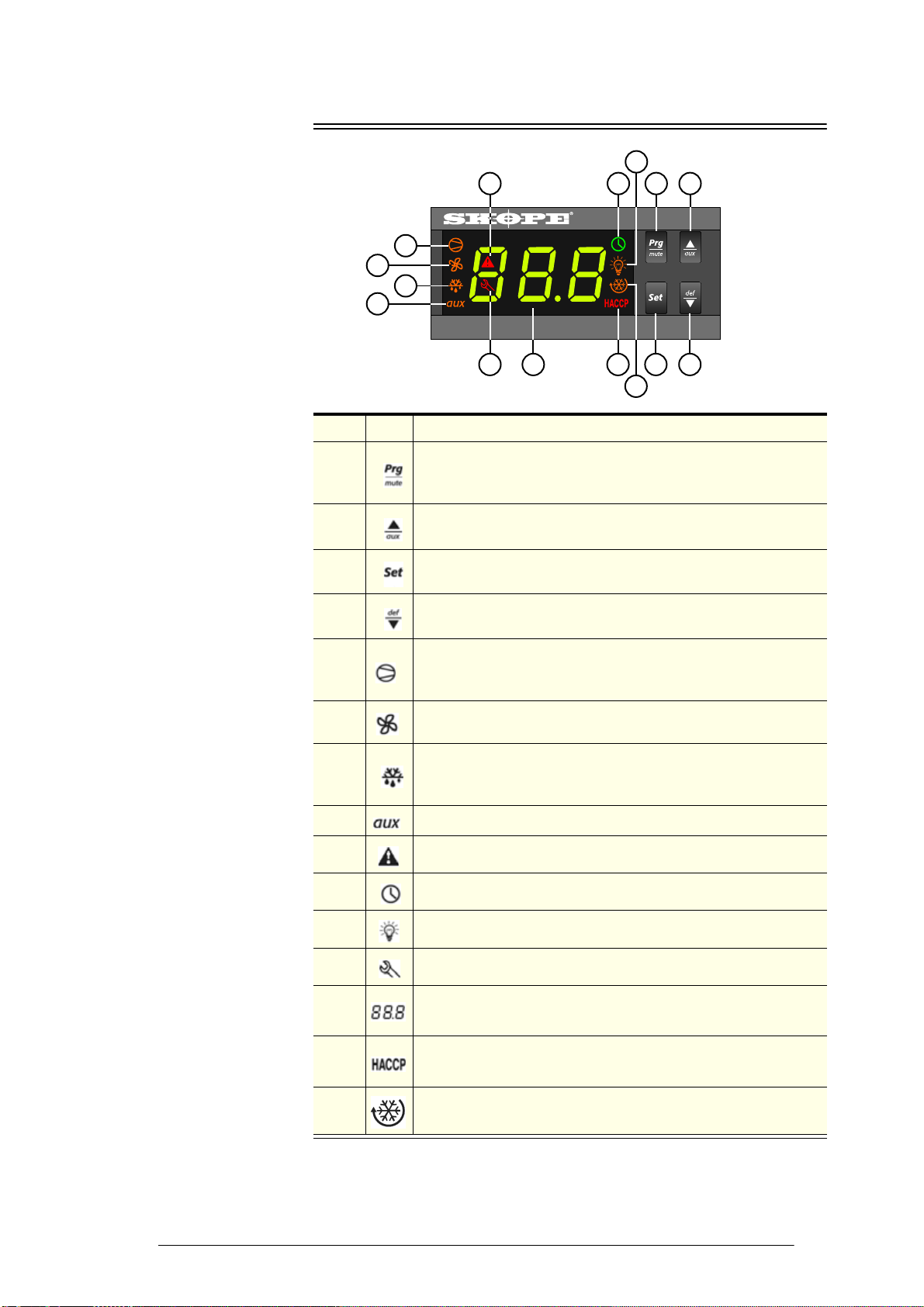
Display
910
11
12
43
15
14
1312
8
7
6
5
Figure 2: Electronic
controller faceplate
Item Icon Function
1
Mute / program: Mutes the audible alarm (buzzer) and
deactivates the alarm relay. To initiate program sets, press for 5
seconds.
2Light switch / up: Press and hold to switch the lights on and off.
To scroll settings up (in program mode).
3Set point: If pressed for more than 2 seconds displays and / or
enables changing the temperature setpoint.
4Manual defrost / down: Press for more than 5 seconds to initiate
manual defrost. To scroll settings down (in program mode).
5
Compressor: ON when the compressor and condenser fan
starts. Flashes when activation of the compressor is temporarily
delayed.
6Fan: Shows when the fan is operational.
7
Defrost: ON when the defrost is activated. Flashes when the
activation of the defrost is temporarily delayed due to procedures
in progress.
8Aux: n.a.
9Alarm: Flashes in the event of alarms.
10 Clock: n.a.
11 Light: n.a.
12 Service: Flashes in the event of malfunctions.
13 DISPLAY: Shows the cabinet temperature. Flashes when the
door is open.
14 HACCP: n.a.
15 CONTINUOUS CYCLE: On when freezer is running in continuous
run mode.
12 SKOPE CAREL ir33 Controller
Service Manual
SKOPE VF Series
Cycles
Defrost Cycle To ensure efficient operation, the electronic controller forces a defrost cycle
when required. During a defrost cycle, the compressor stops, DEF and the
will display on the electronic controller faceplate. The freezer will resume
normal operation once the defrost cycle has finished. A manual defrost can
also be initiated by pressing and holding the button.
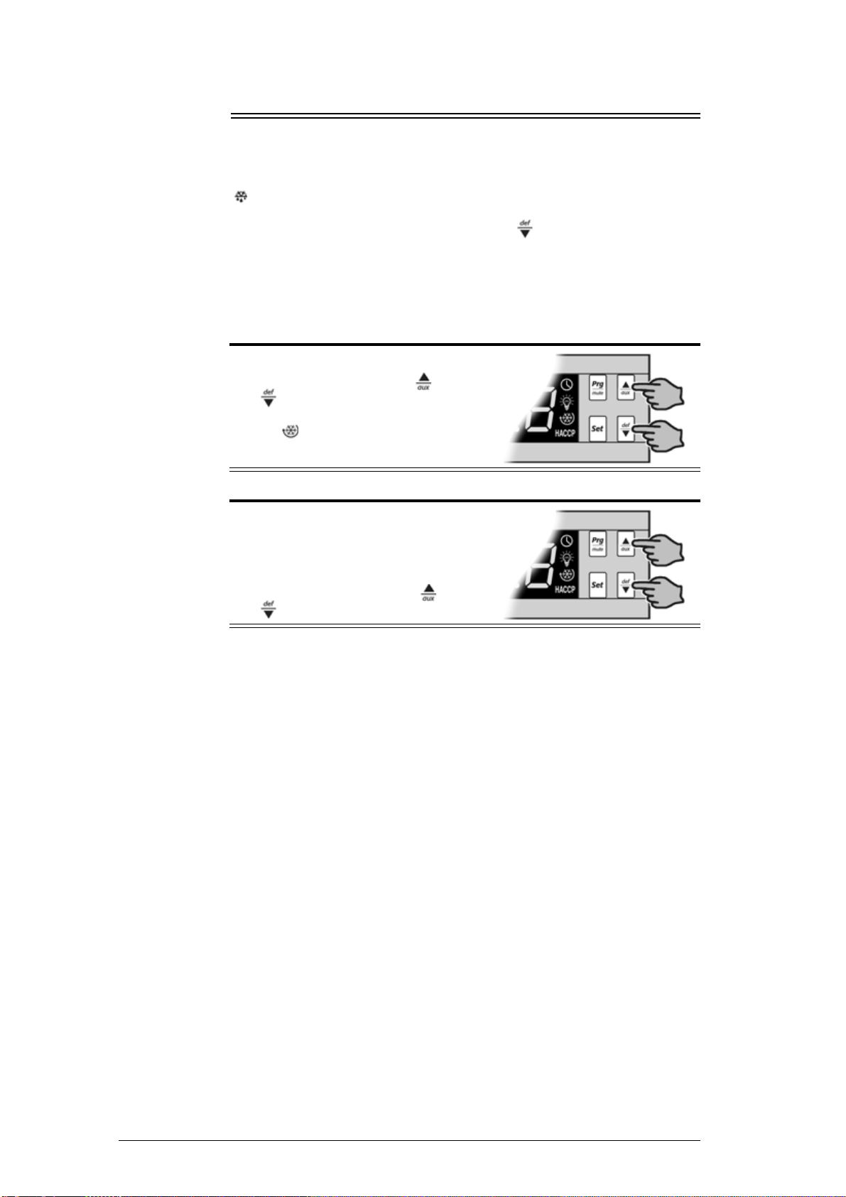
Continuous
Cycle The continuous cycle can be used to pull down the temperature of product
inside the freezer quickly. During a continuous cool down the compressor
runs continuously for a set time.
To start a continuous cycle
To stop a continuous cycle
1. While the freezer is switched on and
running, press and hold the and
buttons for five seconds.
The symbol will display during a
continuous cycle.
1. The electronic controller will
automatically stop the continuous cycle
after a period of time.
The continuous cycle can be stopped
by pressing and holding the and
buttons for five seconds.

13
SKOPE VF Series
SKOPE CAREL ir33 Controller
Service Manual
Temperature Probes
Three temperature probes feed data to the electronic controller - the control,
ambient and evaporator probes. Refer to page 73 for information on
servicing the probes.
Control Probe The control probe controls the freezertemperature and provides the freezer
temperature for the electronic controller to display.
Ambient Probe The ambient probe measures the temperature around the refrigeration unit
and activates the high ambient (HO) alarm if the temperature exceeds 40°C
(freezers) or 32°C (ice storage cabinets). Instances of high ambient alarm
activation are recorded and can be reviewed by accessing the parameters
and reviewing the AHO parameters (see page 20).
Evaporator
Probe The evaporator probe measures the evaporator coil temperature. The
evaporator coil temperature is used for evaporator fan operation (fan will
start when evaporator coil temperature drops to -8°C) and to stop the defrost
cycle (defrost cycle stops when evaporator temperature raises to +4.5°C).
Temperature
Probe Reading The temperature of each of the three temperature probes can be displayed
by pressing and holding both the and keys simultaneously for 5
seconds.
To display the temperature probe readings
Temperature probe readings
1. Press and hold both
the and keys simultaneously
for 5 seconds.
2. Press and hold the key to scroll the
probes (see table below). The key
is not active for this function. This
function will time out after 60 seconds
(cannot be turned off prior to 60
seconds elapsed time).
Display Description
P_1 Control probe temperature
P_2 Evaporator probe temperature
P_3 Ambient probe temperature
P_4 Unused
P_5 Unused

14 SKOPE CAREL ir33 Controller
Service Manual
SKOPE VF Series
Alarms
The following table explains messages that the electronic controller displays and related alarms.
Alarms signal unexpected operational changes in the freezer and stop when action is taken to
resolve the problem.
Controller alarms
Code Display
Icon
Alarm
Description
Action
Flashing
Product HIGH
temperature alarm
1. Check the cabinet product loading to ensure ventilation slots are not
blocked and that product does not overhang the shelves.
2. Ensure the cabinet is installed with good refrigeration unit ventilation.
3. Check and clean the condenser coil.
4. Unplug cabinet from the power supply for 1 minute, then reconnect to
power supply.
The alarm will automatically reset once the product has returned to
temperature specification.
Flashing
Product LOW
temperature alarm
Door open alarm. Door
has been open for
longer than 2 minutes.
Flashes between
cabinet temperature
and dor alarm.
1. Check door is closed.
2. Check door switch operation and wiring.
High ambient alarm 1. Check ventilation and operating conditions. Refer to ventilation label
to ensure correct ventilation.
High pressure
alarm
1. Check and clean the condenser coil.
2. Check condenser fan operation.
Flashing
Control probe fault
1. Check probe connection and wiring.
2. Check probe resistance.
3. Replace probe.
Flashing
Evaporator probe
fault
Flashing
Ambient probe fault
None Defrost over-time
limit 1. Check defrost elements are operating correctly.
Flashing
Real-time clock
fault
1. Unplug cabinet from the power supply for 1 minute, then reconnect to
power supply.
2. Replace controller.
Flashing
Controller E prom
error
Flashing
Controller E prom
error
None Start defrost
request
None
None End defrost request
15
SKOPE VF Series
SKOPE CAREL ir33 Controller
Service Manual
Programming
Set-Point The VF Freezer Range is manufactured with a pre-set control temperature
set-point. If this set-point does not match your required storage temperature
it is recommended that you change the set-point accordingly. The set-point
can be adjusted between a temperature range as detailed in the table below.
Temperature set-point
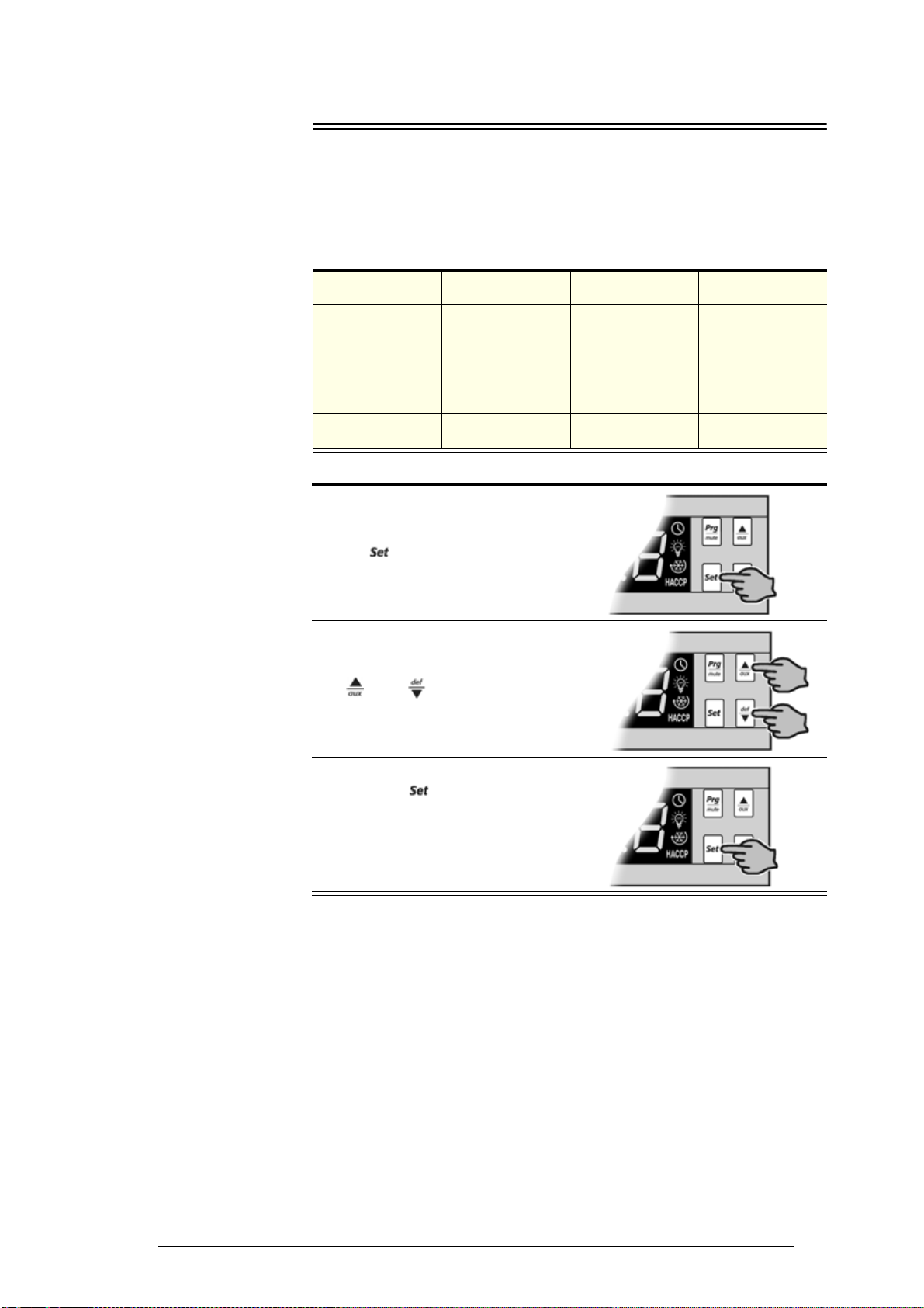
To view and adjust the temperature set-point
Parameter set Operational mode Factory set-point Adjsutable
temperature range
485 BN1
Glass door lit
integral freezer &
solid door unlit
integral freezer
-21°C -26°C to -16°C
485 BN2 Solid door lit
integral freezer -21°C -26°C to -16°C
485 BN3 Glass door ice
storage cabinet -12°C -18°C to -12°C
1. To view the set-point: press and hold
the key for 2 seconds, until the
set-point value flashes
2. To adjust the set-point: press either the
and keys to display the
required set-point value.
3. Press the key again to memorise
the new set-point value. If this is not
done within 60 seconds, changes will
be lost and you will need to repeat the
above procedure.

16 SKOPE CAREL ir33 Controller
Service Manual
SKOPE VF Series
Controller
Reset To delete program modifications and reset the controller to SKOPE default
program, to change the cabinet operational mode (e.g. change use from
freezer to ice storage cabinet), or when a replacement controller is being
fitted, a ‘Controller Reset’ must be performed.
To reset the controller
1. Disconnect the freezer from the power supply.
2. Press and hold the key while
plugging the freezer into the power
supply (this may require two people).
After a few seconds the controller is
reset and program mode ‘bn0’ is
displayed. The controller must never be
left in program mode ‘bn0’ as failure
will occur.
3. Press the or keys to select the
appropiate bn program (see page 17).
4. Immediately press the key to
confirm the preferred program. If not
confirmed within 60 seconds the
freezer will remain in program mode
‘bn0’ (and cause failure). If this occurs,
repeat the above procedure.
17
SKOPE VF Series
SKOPE CAREL ir33 Controller
Service Manual
Default Program Configuration
Factory Default Configuration of the controller is set by SKOPE to a specific
SKOPE Product. The factory default cannot be altered in the field. A label on
the controller box indicates the default program configuration number (e.g.
VF Series integral ‘Program 485’).
BN Parameter
Sets Program 485 includes 3 parameter sets (BN1, BN2 and BN3) for use with
VF Series cabinet variations. The BN set can be changed by performing a
controller reset (see “Controller Reset” on page 16) and selecting the
appropiate BN set. Refer to the table below for BN set operational mode
variations.
BN set variations
Field
Adjustable
Programming
Within each program set are field adjustable (Type C) parameters. To assist
with locating, the parameters can be displayed in groups detailed in the table
below. Non-useful parameters are hidden.
Parameter groups
Changes to SKOPE factory default programs are not recommended.
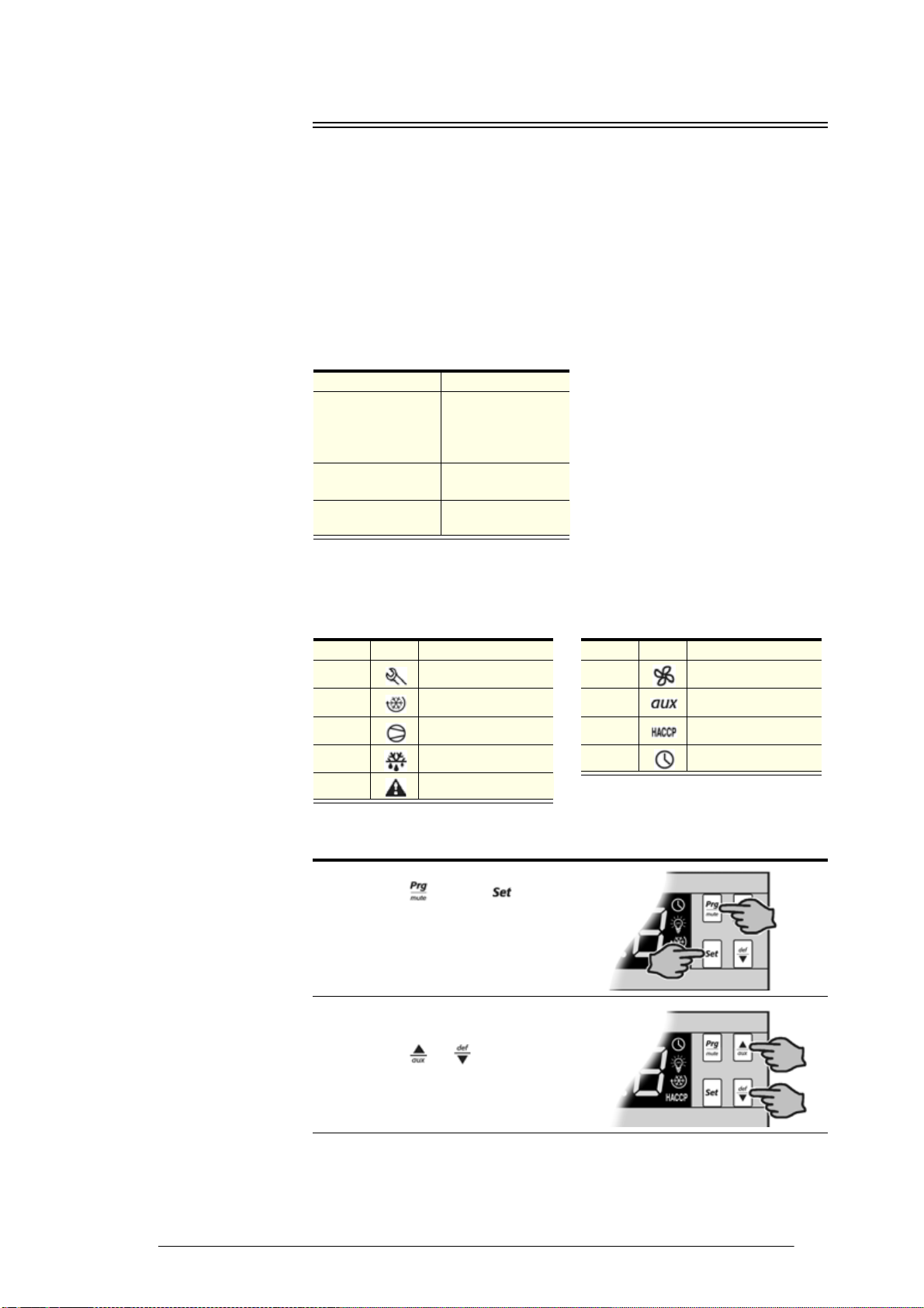
To access Type C parameters
Parameter set Operational mode
485 BN1
Glass door lit
integral freezer &
solid door unlit
integral freezer
485 BN2 Solid door lit
integral freezer
485 BN3 Glass door ice
storage cabinet
Display Icon Group Display Icon Group
Pro Probe Fan Fan
Ctl Temperature CnF General
CMP Compressor HcP HACCP
dEF Defrost rtc Real time clock
ALM Alarm
1. Press the key and keys
together for more than 5 seconds.
The display will show either ‘00’ or ‘-
1’, representing the password
prompt.
2. Press the or keys until
displaying the password number ‘66’
Continued over page

18 SKOPE CAREL ir33 Controller
Service Manual
SKOPE VF Series
To modify ‘Type C’ parameters
3. Confirm by pressing the key. The
display will show the code of the first
modifiable ‘Type C’ parameter.
1. Press the or keys until
reaching the parameter to be modified.
When scrolling, an icon appears on the
display representing the category the
parameter belongs to.
2. Alternatively, press the key to
display a menu that is used to quickly
access the group of parameters to be
modified (see table on previous page).
3. Scroll the menu with
the or keys. The display shows
the codes of the various categories of
parameters.
4. When having reached the desired
category, press the key to move
directly to the first parameter in the
category.
5. At this stage, continue to scroll the
parameters or press the key to
return to the categories.
6. Press the key to display the value
associated with the parameter.
7. Increase or decrease the value using
the or keys respectively.
Continued over page

19
SKOPE VF Series
SKOPE CAREL ir33 Controller
Service Manual
8. Press the key to temporarily save
the new value and return to the display
of the parameter code.
9. Repeat the operations from point 1 or
point 2 on the previous page.
10. If the parameter has sub-parameters,
press the key to display the first
sub-parameter.
11. Press the or keys to display all
the sub-parameters.
12. Press the key to display the
associated value.
13. Increase or decrease the value using
the or keys respectively.
14. Press the key to temporarily save
the new value and return to the display
of the sub-parameter code.
15. Press the key to return to the
display of the parent parameter.
16. Press the key for more than five
seconds to store the new values of the
modified parameters.

20 SKOPE CAREL ir33 Controller
Service Manual
SKOPE VF Series
Display Stability
To slow down rapid fluctuations from door openings and more closely
represent actual product temperature, change the probe parameters as
detailed below.
To change the display stability, adjust parameter ‘/3’ (SKOPE default
moderate stabilisation = 8).
To display setpoint permanently, change parameter’/tl’ from 1 to 7.
Parameters
Only an authorised service agent should change the parameters. A label on
the top of the controller indicates the factory parameter program. Refer to
the tables below for parameters included in this service manual. Refer to
“Field Adjustable Programming” on page 17 for information on accessing
and changing the parameters.
Parameter sets
Continued over page
Program No. Model Page
P485-BN1 Glass door lit integral freezer & solid door unlit integral
freezer 20
P485-BN2 Solid door lit integral freezer 21
P485-BN3 Glass door lit ice storage cabinet 24
This manual suits for next models
16
Table of contents
Other Skope Freezer manuals

Skope
Skope VF650 User manual

Skope
Skope PG600VF User manual

Skope
Skope ActiveCore SKFT1500N-A-WG User manual

Skope
Skope TMEF Series User manual

Skope
Skope PG Series User manual

Skope
Skope BC070-CB User manual

Skope
Skope Centaur Series User manual

Skope
Skope PG Series User manual

Skope
Skope SERENE SC430N User manual

Skope
Skope ProSpec Series User manual


