Skope ActiveCore TMF650N Series User manual

TMF / SKFT-N ActiveCore
SKOPE Top Mount Freezer
Hydrocarbon
Service Manual
MAN80227 Rev. 1.0 Dec. 2021

TMF / SKFT-N ActiveCore
SKOPE Top Mount Freezer
Hydrocarbon
Service Manual
MAN80227
Rev. 1.0 Dec. 2021
© 2021 SKOPE Industries Limited. All rights reserved.
SKOPE Industries Limited reserve the right to alter specifications without notice.
is a registered trademark of SKOPE Industries Limited.
SKOPE INDUSTRIES LIMITED
Head Office
PO Box 1091, Christchurch
New Zealand
NZ: 0800 947 5673
E-mail: [email protected]
Website: www.skope.com
Trademark Infringement
The SKOPE trademark on this product is infringed if the owner, for the time being, does
any of the following:
• Applies the trade mark to the product after their state, condition, get-up or packaging
has been altered in any manner
• Alters, removes (including part removal) or obliterates (including part obliteration) the
trade mark on the product
• Applies any other trade mark to the product
• Adds to the product any written material that is likely to damage the reputation of the
trade mark
Notice of the above contractual obligations passes to:
• Successors or assignees of the buyer
• Future owners of the product

SKOPE TMF-N ActiveCore Series
Service Manual iii
CONTENTS
1Servicing Hydrocarbon
Overview . . . . . . . . . . . . . . . . . . . . . . . . . . . . . . . . . . . . . . . . . . . . . . .6
SKOPE HC Service Requirements . . . . . . . . . . . . . . . . . . . . . . . . . . .7
2Specifications
Models. . . . . . . . . . . . . . . . . . . . . . . . . . . . . . . . . . . . . . . . . . . . . . . . .8
3Electronic Controller
Overview . . . . . . . . . . . . . . . . . . . . . . . . . . . . . . . . . . . . . . . . . . . . . . .9
Apps . . . . . . . . . . . . . . . . . . . . . . . . . . . . . . . . . . . . . . . . . . . . . . . . . .9
SCS Connect Field App . . . . . . . . . . . . . . . . . . . . . . . . . . . . . . . . . . . . . . . 9
SCS Connect Track App . . . . . . . . . . . . . . . . . . . . . . . . . . . . . . . . . . . . . . 9
SKOPE Connect App . . . . . . . . . . . . . . . . . . . . . . . . . . . . . . . . . . . . . . . . 9
Controller Faceplate . . . . . . . . . . . . . . . . . . . . . . . . . . . . . . . . . . . . .10
Buttons and Display . . . . . . . . . . . . . . . . . . . . . . . . . . . . . . . . . . . . . . . . . 10
Service Mode . . . . . . . . . . . . . . . . . . . . . . . . . . . . . . . . . . . . . . . . . . . . . . 10
SCS Connect Field App and Track App. . . . . . . . . . . . . . . . . . . . . . .12
Connecting . . . . . . . . . . . . . . . . . . . . . . . . . . . . . . . . . . . . . . . . . . . . . . . 12
App Categories . . . . . . . . . . . . . . . . . . . . . . . . . . . . . . . . . . . . . . . . . . . . 13
Faults and Alarms . . . . . . . . . . . . . . . . . . . . . . . . . . . . . . . . . . . . . . .15
4Wiring
Model: TMF/SKFT650N/1000N . . . . . . . . . . . . . . . . . . . . . . . . . .19
Notes . . . . . . . . . . . . . . . . . . . . . . . . . . . . . . . . . . . . . . . . . . . . . .21
5Spare Parts
Main Assembly - TMF/SKFT650N Series . . . . . . . . . . . . . . . . . . . . .22
Parts — Main Assembly TMF650N Series . . . . . . . . . . . . . . . . . .22
Main Assembly - TMF/SKFT1000N Series . . . . . . . . . . . . . . . . . . . .23
Parts — Main Assembly TMF1000N Series . . . . . . . . . . . . . . . . .23
Cabinet Assembly - TMF650N Series . . . . . . . . . . . . . . . . . . . . . . . .24
Parts — Cabinet Assembly TMF650N Series . . . . . . . . . . . . . . .24
Cabinet Assembly - TMF1000N Series. . . . . . . . . . . . . . . . . . . . . . .25
Parts — Cabinet Assembly TMF1000N Series . . . . . . . . . . . . . .25
Glass Door Assembly . . . . . . . . . . . . . . . . . . . . . . . . . . . . . . . . . . . .26
Parts — Glass Door Assembly . . . . . . . . . . . . . . . . . . . . . . . . . . .26
Sign Assembly. . . . . . . . . . . . . . . . . . . . . . . . . . . . . . . . . . . . . . . . . .27
Parts — Sign Assembly TMF650N . . . . . . . . . . . . . . . . . . . . . . .27
Parts — Sign Assembly TMF1000N . . . . . . . . . . . . . . . . . . . . . .27
Unit Assembly UTHDNI-0043 . . . . . . . . . . . . . . . . . . . . . . . . . . . . . .28
Parts — Unit Assembly . . . . . . . . . . . . . . . . . . . . . . . . . . . . . . . .29
Electronic Controller Assembly . . . . . . . . . . . . . . . . . . . . . . . . . . . . .30
Parts — Electronic Controller . . . . . . . . . . . . . . . . . . . . . . . . . . . .30
Unit Junction Box Assembly . . . . . . . . . . . . . . . . . . . . . . . . . . . . . . .31
Parts — Unit Junction Box . . . . . . . . . . . . . . . . . . . . . . . . . . . . . .31
6Installation
Installation Guidelines. . . . . . . . . . . . . . . . . . . . . . . . . . . . . . . . . . . .32
Ventilation Requirements . . . . . . . . . . . . . . . . . . . . . . . . . . . . . . . . .33
Door Handles . . . . . . . . . . . . . . . . . . . . . . . . . . . . . . . . . . . . . . . . . .34
Fitting Door Handles . . . . . . . . . . . . . . . . . . . . . . . . . . . . . . . . . . . . . . . . 34
Removing Door Handles . . . . . . . . . . . . . . . . . . . . . . . . . . . . . . . . . . . . . 35
Shelves . . . . . . . . . . . . . . . . . . . . . . . . . . . . . . . . . . . . . . . . . . . . . . .36
Shelf Clips . . . . . . . . . . . . . . . . . . . . . . . . . . . . . . . . . . . . . . . . . . . . . . . . 36

SKOPE TMF-N ActiveCore Series
Service Manual
iv
Repositioning Shelves . . . . . . . . . . . . . . . . . . . . . . . . . . . . . . . . . . . . . . . 36
7Operation
Loading Product . . . . . . . . . . . . . . . . . . . . . . . . . . . . . . . . . . . . . . . .37
Light Switch. . . . . . . . . . . . . . . . . . . . . . . . . . . . . . . . . . . . . . . . . . . .37
Cabinet Heat Control. . . . . . . . . . . . . . . . . . . . . . . . . . . . . . . . . . . . .38
Overview . . . . . . . . . . . . . . . . . . . . . . . . . . . . . . . . . . . . . . . . . . . . . . . . . 38
Dew Point Sensor . . . . . . . . . . . . . . . . . . . . . . . . . . . . . . . . . . . . . . . . . . 38
Temp Sensor . . . . . . . . . . . . . . . . . . . . . . . . . . . . . . . . . . . . . . . . . . . . . . 38
Hot Gas Defrost . . . . . . . . . . . . . . . . . . . . . . . . . . . . . . . . . . . . . . . .39
Refrigeration System Diagnostics - Function Test . . . . . . . . . . . . . .40
Refrigeration System Table. . . . . . . . . . . . . . . . . . . . . . . . . . . . . . . .41
Cabinet Heat Control. . . . . . . . . . . . . . . . . . . . . . . . . . . . . . . . . . . . .42
Overview . . . . . . . . . . . . . . . . . . . . . . . . . . . . . . . . . . . . . . . . . . . . . . . . . 42
Trouble Shooting . . . . . . . . . . . . . . . . . . . . . . . . . . . . . . . . . . . . . . . . . . . 42
Adjusting Heater Power . . . . . . . . . . . . . . . . . . . . . . . . . . . . . . . . . . . . . 43
Procedure . . . . . . . . . . . . . . . . . . . . . . . . . . . . . . . . . . . . . . . . . . . . . . . . 43
Dew Point Sensor . . . . . . . . . . . . . . . . . . . . . . . . . . . . . . . . . . . . . . . . . . 43
Temp Sensor . . . . . . . . . . . . . . . . . . . . . . . . . . . . . . . . . . . . . . . . . . . . . . 44
Compressor and Inverter Information . . . . . . . . . . . . . . . . . . . . . . . .45
Inverter LED Indication . . . . . . . . . . . . . . . . . . . . . . . . . . . . . . . . . . . . . . 45
Trouble Shooting . . . . . . . . . . . . . . . . . . . . . . . . . . . . . . . . . . . . . . . . . . . 45
Compressor . . . . . . . . . . . . . . . . . . . . . . . . . . . . . . . . . . . . . . . . . . . . . . . 46
Compressor Inverter . . . . . . . . . . . . . . . . . . . . . . . . . . . . . . . . . . . . . . . . 47
8Replacement Procedures
Lighting . . . . . . . . . . . . . . . . . . . . . . . . . . . . . . . . . . . . . . . . . . . . . . .48
Sign Light . . . . . . . . . . . . . . . . . . . . . . . . . . . . . . . . . . . . . . . . . . . . . . . . 51
Doors. . . . . . . . . . . . . . . . . . . . . . . . . . . . . . . . . . . . . . . . . . . . . . . . .52
Alignment Adjustment . . . . . . . . . . . . . . . . . . . . . . . . . . . . . . . . . . . . . . . 52
Height Adjustment . . . . . . . . . . . . . . . . . . . . . . . . . . . . . . . . . . . . . . . . . . 52
Replacing the Gasket . . . . . . . . . . . . . . . . . . . . . . . . . . . . . . . . . . . . . . . 52
Removing and Refitting the Door . . . . . . . . . . . . . . . . . . . . . . . . . . . . . . 52
Adjusting Door Tension . . . . . . . . . . . . . . . . . . . . . . . . . . . . . . . . . . . . . . 54
Replacing the Torsion Bar . . . . . . . . . . . . . . . . . . . . . . . . . . . . . . . . . . . . 54
Refrigeration Unit . . . . . . . . . . . . . . . . . . . . . . . . . . . . . . . . . . . . . . .55
Before Servicing . . . . . . . . . . . . . . . . . . . . . . . . . . . . . . . . . . . . . . . . . . . 55
Refrigeration Unit Assembly . . . . . . . . . . . . . . . . . . . . . . . . . . . . . . . . . . 56
Gas Detector . . . . . . . . . . . . . . . . . . . . . . . . . . . . . . . . . . . . . . . . . . . . . . 57
Leak Detector . . . . . . . . . . . . . . . . . . . . . . . . . . . . . . . . . . . . . . . . . . . . . 57
On-Site Work . . . . . . . . . . . . . . . . . . . . . . . . . . . . . . . . . . . . . . . . . . . . . . 57
Not Cooling Fault . . . . . . . . . . . . . . . . . . . . . . . . . . . . . . . . . . . . . . . . . . 57
Hydrocarbon Workshop . . . . . . . . . . . . . . . . . . . . . . . . . . . . . . . . . . . . . 57
Removing the Unit . . . . . . . . . . . . . . . . . . . . . . . . . . . . . . . . . . . . . . . . . . 59
Replacing the Unit . . . . . . . . . . . . . . . . . . . . . . . . . . . . . . . . . . . . . . . . . 60
Unit Electrics Box Assembly . . . . . . . . . . . . . . . . . . . . . . . . . . . . . . . . . . 61
Unit Cover . . . . . . . . . . . . . . . . . . . . . . . . . . . . . . . . . . . . . . . . . . . . . . . . 62
Condenser Fan . . . . . . . . . . . . . . . . . . . . . . . . . . . . . . . . . . . . . . . . . . . . 62
Evaporator Fan . . . . . . . . . . . . . . . . . . . . . . . . . . . . . . . . . . . . . . . . . . . . 64
Replacing the Controller . . . . . . . . . . . . . . . . . . . . . . . . . . . . . . . . . . . . . 67
Door Switch . . . . . . . . . . . . . . . . . . . . . . . . . . . . . . . . . . . . . . . . . . . . . . . 68
Control Probe . . . . . . . . . . . . . . . . . . . . . . . . . . . . . . . . . . . . . . . . . . . . . 68
Evaporator Probe . . . . . . . . . . . . . . . . . . . . . . . . . . . . . . . . . . . . . . . . . . 69
Condenser Probe . . . . . . . . . . . . . . . . . . . . . . . . . . . . . . . . . . . . . . . . . . 70
Ambient Probe . . . . . . . . . . . . . . . . . . . . . . . . . . . . . . . . . . . . . . . . . . . . 71
Oxygen Free Nitrogen . . . . . . . . . . . . . . . . . . . . . . . . . . . . . . . . . . . . . . . 72
Cleaning . . . . . . . . . . . . . . . . . . . . . . . . . . . . . . . . . . . . . . . . . . . . . .73
Cabinet . . . . . . . . . . . . . . . . . . . . . . . . . . . . . . . . . . . . . . . . . . . . . . . . . . 73
Condenser Coil . . . . . . . . . . . . . . . . . . . . . . . . . . . . . . . . . . . . . . . . . . . . 73
Probe Resistance . . . . . . . . . . . . . . . . . . . . . . . . . . . . . . . . . . . . .74

5
SKOPE TMF-N ActiveCore Series
Service Manual
Probe Resistance (continued) . . . . . . . . . . . . . . . . . . . . . . . . . . . 75
9Troubleshooting
Electronic Controller . . . . . . . . . . . . . . . . . . . . . . . . . . . . . . . . . . . . . 76
Cabinet and Refrigeration Unit . . . . . . . . . . . . . . . . . . . . . . . . . . . . . 76
On-site work procedure by authorised service person . . . . . . . . 78
On-site work procedure (continued) . . . . . . . . . . . . . . . . . . . . . . 79

6Servicing Hydrocarbon
Service Manual
SKOPE TMF-N ActiveCore Series
1Servicing Hydrocarbon
Overview
This ActiveCore freezer range utilises hydrocarbon (HC) R290 as its
refrigerant. R290 is a natural refrigerant that has a very low environmental
impact.
Special service requirements are needed as R290 is a flammable
refrigerant.
Safety hazards
The main hydrocarbon safety hazards are:
Flammable refrigerant.
Venting of hydrocarbon and compressor oil.
Asphyxiation.
Do not interfere with the refrigeration system. All refrigeration maintenance
and repairs must be undertaken according to the SKOPE HC Service
Requirements below.
See “SKOPE HC Service Requirements” on page 7 for more information
including examples of hazardous activities.
Electrical safety precautions
Correct wiring routing is as important as use of correct components for
compliance with safety and radio interference regulations. In order to
maintainsafety andcompliancewith regulations,any wiringthatis disturbed
during servicing must be replaced and secured in its original position.

7
SKOPE TMF-N ActiveCore Series
Servicing Hydrocarbon
Service Manual
SKOPE HC Service Requirements
Servicing must only be performed byApproved SKOPE Service Technicians, and must meet all
requirements in the SKOPE HC Service Policy (available from SKOPE), including the following:
Hydrocarbon work – SKOPE Service Policy
It is the responsibility of the service technician to follow SKOPE’s Hydrocarbon equipment service policy
and by accepting a service work order they agree to the following (where applicable):
xMUST – Ensure all workers are trained in the SAFETY of hydrocarbon products to the appropriate
level for the work required.
xMUST – Follow all Local Safety Regulations relevant to flammable refrigerant gases.
oAustralia should reference - AIRAH Flammable Refrigerants – Safety Guide
oNew Zealand should reference – Flammable Refrigerant Safety Documentation
(Refrigerant License NZ)
xMUST – Adhere to all on-site (workplace) Health and Safety requirements
xMUST – Not modify or alter the design of SKOPE equipment in any way
xMUST – In cases where the refrigeration system is not readily removable from the cabinet; then the
entire cabinet MUST be sent to the Hydrocarbon workshop for repair.
xMUST – ONLY use SKOPE OEM Spare Parts; or identical replacement parts. Any variation in
replacement part may render the system non-compliant and unsafe.
xMUST – Follow all best practice work activities for servicing hydrocarbon refrigerants (SKOPE
recommend attending specific hydrocarbon refrigeration handling training courses). Nitrogen must
be used for purging system before commencing “Hot Work” – brazing.
xMUST – Adhere to relevant SKOPE Service Manual. If any contradiction, the local Regulations take
precedence over SKOPE requirements
xMUST – Work only in suitable, safe and compliant work spaces. Personal Protective Equipment
must always be used when working on Hydrocarbon equipment.
xMUST – Service people diagnosing refrigeration faults must always carry and utilise Flammable Gas
detectors when working on Hydrocarbon equipment.
xMUST – Prior to any service work; know where and how to safely and quickly isolate power supply
to cabinet
xMUST – Not perform any Hot Work (brazing etc.) in the field. These are to be completed in a suitable
service depot / workshop (in a dedicated specific Hazardous Work Area compliant to local
flammable gas regulations)
xMUST – Not transport a refrigeration system with a known active leak. If there is an active leak the
refrigerant must be safely removed (with use of Bullet Piercing Valve or Line Tap valves) before
transporting. Valves must be removed at the hydrocarbon service depot once repair is completed.
xMUST – All hydrocarbon workshop areas must have emergency plans; that includes suitable
evacuation and fire control plans and equipment.
xMUST – Only use refrigerant grade hydrocarbon, to precise mass specified on removable
refrigeration system serial label.
xMUST – Be accurate refrigerant charge; The refrigerant mass is ultra-low charge and must only be
measured in by accurate scales to +/- 1.0gram. Refrigerant MUST not be overcharged; or added to
an already charged system.
xMUST – Use identical drier replacement; as any change will affect gas charge volume; and effect
reliability compliance and safety.
xMUST – Any pipework replacement, must be identical to genuine SKOPE parts.
xMUST – Not introduce a sparking device inside a cabinet or inside a removable refrigeration system.
Battery drills should not be used.
xMUST – Not perform any activity that could stress a refrigeration pipe (unless in a workshop).
xMUST – Get customer authorisation to permanently swap a removable refrigeration system.
xMUST – Have the Wellington Drive SCS Field app installed on a Bluetooth enabled device carried by
the service technician (exception is for cabinets that do not utilise the Wellington Drive Controller).
The app should be utilised for safe, accurate diagnosis of the system and it is required to complete
a controller replacement in the field.
xRECOMMENDED – Have the Wellington Drive SCS Track app installed on a Bluetooth enabled device
carried by the service technician. This passive app collects system data from the Wellington Drive
SCS Connect Controller and transmit it to the cloud.
xLogistics companies may be used to transport a complete refrigerator where no separation of the
refrigeration system occurs. Logistics companies are not required to be contracted to this SKOPE
Service Policy.

8Specifications
Service Manual
SKOPE TMF-N ActiveCore Series
2Specifications
Models
This freezers service manual is applicable to the SKOPE TMF ActiveCore
top mount freezers detailed in the table below. Refer to the relevant product
specification sheet (available on the SKOPE website: www.skope.com) for
specifications.
Series Model SKOPE ID Unit
TMF650N ActiveCore TMF650N-A LTH65GYN
UTHDNI-0043
TMF650N-AC LTH65BYN
TMF1000N ActiveCore TMF1000N-A LHT10GYN
TMF1000N-AC LTH10BYN
SKFT650N ActiveCore SKFT650N-A LT65GYN
SKFT650N-AC LT65BYN
SKFT1000N ActiveCore SKFT1000N-A LT10GYN
SKFT1000N-AC LT10BYN

9
SKOPE TMF-N ActiveCore Series
Electronic Controller
Service Manual
3Electronic Controller
Overview
The freezer is fitted with a Wellington Drive SCS Connect electronic
controller. The controller is located above the door/s and visible from the
outside of the freezer.
Controller servicing can be performed via the controller faceplate, or the
SCS Connect Field app.
This does not control the cabinet body and door heater elements
Apps
SCS Connect
Field App The SCS Connect Field app is designed for service techs, and provides
access to the controller from mobile devices with Bluetooth capability. The
app provides information on data logging, alarm notification and diagnostic
control.
See “SCS Connect Field App and Track App” on page 12 for information on
setting up and using the app.
SCS Connect
Track App The SCS Connect Track app is used to upload data from freezers fitted with
a Wellington SCS Connect electronic controller.
SKOPE
Connect App The SKOPE-connect app is designed for end-users and provides wireless
access to the controller from mobile devices with Bluetooth capability.
The app allows end users to adjust some electronic controller settings
including energy saving modes, open/close hours and preset temperature
set points for specific product.
The app may be useful for diagnostics. Download from
the Google Play Store, or Apple App Store.

10 Electronic Controller
Service Manual
SKOPE TMF-N ActiveCore Series
Controller Faceplate
Buttons and
Display The controller faceplate includes the front display panel and interface
buttons.
Service Mode Service mode can be accessed and used via the SCS Connect Field app
(see “SCS Connect FieldApp and TrackApp” on page 12), or the controller
faceplate (see below).
Note:A9 digit pin code is required to access service mode via the controller
buttons. Contact your User Manager to receive your activation code.
To enable and use service mode via the controller faceplate
12 3 4 5
8 7
11
10
96
No. Description
1Night Mode: Indicator. On during cooler night mode.
2
Display: Indicator. Digital display of cabinet air temperature or messages.
The temperature is what the sensor inside the cooler detects, and not
necessarily the product temperature. However, they may be very close
depending on how the controller is set to sense temperature.
3Light Switch - Night Mode (back/abort): Button. Press to switch the lights
on or off. Press and hold to switch cooler between day and night mode. Used
during programming.
4Up: Button. Used for programming.
5Bluetooth: Indicator. Flashing when connected to a device.
6Defrost Cycle (next/enter): Button. Press and hold to initiate manual defrost.
Used during programming.
7Down: Button. Used for programming.
8Fault - Alarm: Indicator. On during fault or alarm. Note: Alarm message is
also shown on the display during alarm.
9Compressor: Indicator. On when the compressor is running.
10 Defrost Mode: Indicator. On during defrost cycle.
11 Fan: Indicator. ON when evaporator fan running.
1. Press and hold the up and down buttons simultaneously until prompted to
enter the 9 digit pin code.
2. Enter service mode pin code.
3. Use the up, down, back/abort and next/enter buttons to navigate to the
desired category.

11
SKOPE TMF-N ActiveCore Series
Electronic Controller
Service Manual
There are 5 main service mode categories when accessing and using
service mode via the controller faceplate:
Parameters
Provides access and editing of individual controller parameters.
It is not recommended that parameters are changed unless absolutely
necessary. If incorrect parameter settings are suspected, reload the
complete parameter set.
Reset
Returns the controller back to factory settings. Parameter set must be
reloaded after performing a reset.
Manual test
Allows inspection of input values from sensors, and check the effects of
output adjustments to peripherals, and to run preset test routines.
Statistics
Displays logged values and event counts to assist with fine tuning and
diagnostics.
About
Lists the properties of the refrigeration system and the controller, including
cooler model codes, firmware, hardware and software versions.

12 Electronic Controller
Service Manual
SKOPE TMF-N ActiveCore Series
SCS Connect Field App and Track App
Connecting Follow the procedures below to install and set-up the app, and connect to a
controller.
Note: The SCS Connect Field app and Track app is separate from the
SKOPE-connect app.
To install the SCS Connect Field app
To connect to a controller
1. Download and install the Connect Field app or Track app from Google Play or
Apple Store (search for “scs wellington” to find it).
2. When you first run the app, you will be requested to enter an activation code.
Contact your Service Manager or SKOPE to receive your activation code
(you must be connected to the internet at the time of activation).
Your activation code is unique to you, and should NEVER be shared with
anyone else, as it determines your personal access level for the app. The
same code will give you access to all SCS apps you are authorised to use.
3. Once activation is complete, you must define a 4-digit PIN code. This can be
any code unique to you. Each time you start the app, you will be required to
enter this same PIN code. This is to prevent other people accessing the app
from unlocked phones.
4. You can see which databases you are activated against from the “Settings”
screen. You can be activated to more than one database at the same time.
Simply select ACTIVATE ANOTHER DATABASE, and enter the new
databases unique activation code, as in Step 2.
1. Check that the Bluetooth logo on the top right of the controller faceplate is
unlit, and when connection is achieved it will begin to flash.
Note: A flashing Bluetooth logo indicates that the controller is currently
connected to a device.
2. Open the SCS Connect Field app.
3. Select a controller to connect to from the list of visible controllers.
Note: This list is filtered by your activation permissions, so devices you are
not authorised to connect to will not be displayed.
4. Select ‘connect’ to connect to the controller.
5. Check that the Bluetooth logo on the top right of the controller faceplate is
flashing, indicating that the controller is connected.

13
SKOPE TMF-N ActiveCore Series
Electronic Controller
Service Manual
App
Categories Various options are available in the app menu to provide information about
the connected controller and it’s cooler. Depending on user access level,
some menu options may not be available.
Home screen
The home screen shows a graphic representation of the current state of the
cooler or freezer being controlled.
Output control
Provides control of the controller input sensors and switches, and output
relays.
Edit parameters
Provides access and editing of individual controller parameters.
Note: Parameter changes must be recorded on warranty/job card.
It is not recommended that parameters are changed unless absolutely
necessary. If incorrect parameter settings are suspected, reload the
complete parameter set. Note: Updated parameters are not applied until
DISCONNECT has been selected from the menu (after loading new
parameter set).

14 Electronic Controller
Service Manual
SKOPE TMF-N ActiveCore Series
Load parameter file
Allows reloading of cooler default parameter set or changing to new
parameter set. See See “Replacing the Controller” on page 65 for
instructions. Note: Updatedparametersare not applieduntil DISCONNECT
has been selected from the menu (after loading new parameter set).
Statistics
Information from the past seven days on cooler activity including
temperatures, door openings and alarms.
SCS info
Controller version and cooler asset information.
SCS setup
Add or change SCS info (see above).
Disconnect
Disconnect from currently connected controller.
Settings
Change app general settings.
Model Number TMF-N Models SKTF-N Models
Parameter Numbers 613 ✔ ✔

15
SKOPE TMF-N ActiveCore Series
Electronic Controller
Service Manual
Faults and Alarms
The following table explains faults and alarms that the electronic controller may log and display.
If a fault occurs, the fault - alarm indicator is lit on the controller faceplate, but no message is
displayed. Faults do not affect product temperature, and require no action from the shop owner.
Alarms are logged and the alarm message is displayed on the controller faceplate. Alarms may
result in abnormal product temperature.
Some faults and alarms can be cleared by the shop owner, and others can only be cleared by a
service technician.
If the cooler is connected to the power supply and has warm product, check the SCS Connect Field
App for active fault or alarm, and investigate. If the cooler does not have an active fault or alarm,
check the app statistics to determine if and when the controller signalled a fault or alarm.
Refer to the tables below for faults and alarm descriptions and possible causes and actions. The
service tech type column refers to the service tech skill level required to complete a task. Refer to
the “SKOPE HC Service Requirements” on page 7 for service tech type details.
Faults
Alarms
Description Service tech
type Possible root cause
Door left open.
The door has been open for several minutes. 1, 2, 3, 4 - door not self closing (torsion fault)
- door switch / circuit
- controller
Excessive door open counts
Over-voltage protection
The maximum allowable mains supply voltage has
been exceeded. The cabinet has temporarily shut
down to prevent damage and will restart once the
supply voltage decreases.
1, 2, 3, 4 - should be a one off; if continues:
- line voltage / rural
- voltage setting parameter
- controller
Under-voltage protection
The mains supply voltage has dropped below the
minimum allowable level. The cabinet has temporarily
shut down to prevent damage and will restart once the
supply voltage increases.
1, 2, 3, 4 - should be a one off; if continues:
- power supply overloaded / multibox
- line voltage / rural.
- voltage setting parameter
- controller
High condensing temperature protection
The system was operating at an elevated temperature
and has temporarily shut down to prevent damage.
Extended operation in this condition may result in
ALARM 15, increased energy consumption and a
reduction in cabinet life. This alarm may be caused by
very high ambient temperature.
2, 3, 4
NO swap unit required
- condenser not clean
- poor installation / ventilation
- condenser fan motor / blade
- controller
Excessive compressor cycling protection
The system has been turning on and off too frequently. 2, 3, 4
Take spare unit in case refrigeration system fault.
- condenser blocked
- poor installation / ventilation
- cabinet / unit gasket seals leaking
- door not self closing / gasket leaking
- product; hot / blocking cabinet airflow
- overloaded from excess door openings /
ambient
- fan motor / blade (condenser / Evap)
- controller
- compressor / gas leak = SWAP unit
Code Description Service tech
type Possible root cause
dor Door left open.
The door has been open for several minutes.
Will revert to door left open FAULT after 10
minutes (see faults table on previous page).
1, 2, 3, 4 - door not self closing (torsion fault)
- door switch / circuit
- controller

16 Electronic Controller
Service Manual
SKOPE TMF-N ActiveCore Series
8Estimated product temperature below
allowable range
The estimated product temperature has been
below the allowable range for longer than the
permissible time. Potential causes are: an
empty or partially filled cabinet, or low ambient
temperature.
1, 2, 3, 4 - low ambient
- App settings
- controller
9Estimated product temperature above
allowable range
The estimated product temperature has been
above the allowable range for longer than the
permissible time. Potential causes are:
excessive door openings, door being left
open, or warm product loaded into cabinet.
2, 3, 4 NO Swap unit required to be taken (but may be
required as fault could still be with sealed
refrigeration system)
- condenser blocked
- poor installation / ventilation
- frozen blocked evap coil
- unit gasket leaking (to cabinet seal / lid seal)
- door leaking air (bad gasket / door not self
closing)
- product; hot / blocking cabinet airflow
- overloaded from excess door openings / ambient
- fan motor / blade (condenser / Evap)
- App settings
- controller
- compressor / gas leak = arrange SWAP unit
15
Excessive condensing temperature protection
The system was operating at an excessive
temperature and has shut down to prevent
permanent damage. This alarm may occur
due to very high ambient temperature.
2, 3, 4
NO swap unit required
- condenser not clean
- poor installation / ventilation
- condenser fan motor / blade
- controller
17 Control probe failure
A critical system sensor has failed and the
cabinet can no longer operate. 2, 3, 4 NO swap unit required
- control Probe / circuit
- controller
18
Electrical over-current protection activated
The compressor was drawing too much
current and has shut down to prevent
permanent damage.
2, 3, 4
Take spare unit in case refrigeration system fault.
- condenser blocked
- poor installation / ventilation
- cabinet / unit gasket seals leaking
- door not self closing / gasket leaking
- product; hot / blocking cabinet airflow
- overloaded from excess door openings / ambient
- fan motor / blade (condenser / Evap)
- controller
- compressor / gas leak = SWAP unit
19
Failed to reach set temperature
The refrigeration system has been operating
continuously for a long period without
reaching the set temperature.
2, 3, 4
Take spare unit in case refrigeration system fault.
- condenser blocked
- poor installation / ventilation
- frozen blocked evap coil
- cabinet seal leaking / door / unit
- product; hot / blocking cabinet airflow
- overloaded from excess door openings / ambient
- fan motor / blade (condenser / Evap)
- controller
- compressor / gas leak = SWAP unit
20
Over cooling product
The internal temperature is too low. The
system has temporarily shut down until the
temperature has returned to normal. This can
occur if the set temperature has been raised
by a large amount.
1, 2, 3, 4 - confirm if really too cold; change parameters
accordingly
22 Evaporator fan over-current protection
The current supplied to the evaporator fan
motor is too high. 2, 3, 4
NO swap unit required
- faulty fan motor
- fan blade fault (imbalance / debris / blockage)
- controller
23 Condenser fan over-current protection
The current supplied to the condenser fan
motor is too high. 2, 3, 4
NO swap unit required
- faulty fan motor
- fan blade fault (imbalance / debris / blockage)
- controller
24 Controller communication error
Controller has lost communication channels. 1, 2, 3, 4 - App
- controller / circuit
Code Description Service tech
type Possible root cause

17
SKOPE TMF-N ActiveCore Series
Electronic Controller
Service Manual
Continued over page
25 Controller update failed
Controller update could not be completed. 1, 2, 3, 4 - App
- controller / circuit
26 Controller hardware failure
Controller hardware has failed. 1, 2, 3, 4 - App
- controller / circuit
27
Probe failure
A non-critical system probe has failed. The
cabinet will continue to operate with partial
function but requires service.
2, 3, 4 NO swap unit required
- Evap probe / connections
- controller
28 No downward tendency
The temperature is no longer decreasing. 2, 3, 4
Take spare unit in case refrigeration system fault.
- condenser blocked
- poor installation / ventilation
- cabinet / unit gasket seals leaking
- door not self closing / gasket leaking
- product; hot / blocking cabinet airflow
- overloaded from excess door openings / ambient
- fan motor / blade (condenser / Evap)
- controller
- compressor / gas leak = SWAP unit
29 Compressor cutting out
The compressor cut out on its internal
protection or pressure switch. 2, 3, 4
Take spare unit in case refrigeration system fault.
- condenser blocked
- poor installation / ventilation
- cabinet seal leaking / door / unit
- product; hot / blocking cabinet airflow
- overloaded from excess door openings / ambient
- fan motor / blade (condenser / Evap)
- controller
- compressor / gas leak = SWAP unit
30 Excessive automatic defrosting
The system is automatically defrosting too
frequently. 2, 3, 4
Take spare unit in case refrigeration system fault.
- door not self closing / gasket leaking
- Evaporator probe
- Evaporator motor / fan
- controller
- compressor / gas leak = SWAP unit
31 Compressor stalling
The compressor is stalling on start up. 2, 3, 4
Take spare unit in case refrigeration system fault.
- condenser blocked
- poor installation / ventilation
- cabinet / unit gasket seals leaking
- door not self closing / gasket leaking
- product; hot / blocking cabinet airflow
- overloaded from excess door openings / ambient
- fan motor / blade (condenser / Evap)
- controller
- compressor / gas leak = SWAP unit
Code Description Service tech
type Possible root cause

18 Electronic Controller
Service Manual
SKOPE TMF-N ActiveCore Series
LEGEND
S13/P13 Hot Gas Solenoid Unit Socket/Plug (White 3-way)
S14/P14 Not Used
S15/P15 Compressor Unit Socket/Plug (Blue 4-way)
S16/P16 Evaporator Sensor Socket/Plug (Black 2-way)
S17/P17 Cabinet Sensor Socket/Plug (Blue 2-way)
S18/P18 Condenser Motor Unit Socket/Plug (Red 4-way)
S19/P19 Evaporator Motor Unit Socket/Plug (White 4-way)
S20/P20 Condenser Sensor Socket/Plug (Red 2-way)
T1 Unit Terminals
T2 EMI Filter Box Terminals
External Sockets/Plugs
S21/P21 Evaporator Motor Extension Socket/Plug (Red 4-way)
S22/P22 Ambient Sensor Socket/Plug (White 2-way)
S23/P23 Programming/Comms Port Socket (Blue 4-way)
S24/P24 LED Driver DC Out Put Socket/Plug (Red 2-way)
S25/P25 LED Lighting Loom Socket/Plug (White 6-way)
S26/P26 Heater Controller Socket/Plug (White 4-way)
S27/P27 Cabinet Heating Loom and Ferrite Plug/Socket (Black 3-way)
S28/P28 Hot Gas Solenoid Extension Socket/Plug (White 4-way)
S29/P29 Heater Controller Temperature Controller
S30/P30 Heater Controller Dew Point Sensor
S31/P31 LED Driver AC Extension Flex Socket/Plug (White 3-way)
S32/P32 Unfiltered VSD Supply Socket/Plug (Yellow 4-way)

19
SKOPE TMF-N ActiveCore Series
Wiring
Service Manual
4Wiring
Model: TMF/SKFT650N/1000N
BU
S18-2 P18-2
P6-1 S6-1
P3-1 S3-1
P3-4 S3-4
P6-4 S6-4
BN
BU
BN
S21-4 P21-4
S21-2 P21-2
CondenserFan
BN
S18-4 P18-4
Evaporator Fan
BU
BU
BU
S2-1 P2-1
S2-2 P2-2
S2-3 P2-3
S2-5 P2-5
BK
BK
OG
BK
BK
BK
BK
BK
Cabinet
Probe
Evaporator
Probe
BN
L
BU
N
BN BU
T1-2
GNY
E
EMC Filter
BUBN
P17-2 S17-2
S6-2 P6-2
WDTL
SCS
Controller
L N
C
R
R
SSR S1
S2
SSR
Comp.
0V
+
1
2
3
AD5
DI1
0V AD1
DI2
0V AD2
DI3
0V AD3
DI4
5V
0V AD4
BK
BK
BN BU
P3-2 S3-2
S19-2 P19-2
S19-4 P19-4
BN
BK
BK
RD
BN
WH
S4-2 P4-2
BN
P18-1 S18-1
BU
BU
P21-1 S21-1
P19-1 S19-1
BU
BN
WH
RD
Door Switch
WH
WH
RD
Door Switch
BK
BK
Condenser
Probe
P17-1 S17-1
P16-1 S16-1
P16-2 S16-2
P20-2 S20-2
P20-1 S20-1
S23-4
S23-1
S23-3
P22-1 S22-1
BK
BK
P22-2 S22-2BKP7-2 S7-2
S2-4 P2-4
RD
BU BU
WH
P7-1 S7-1
WH
BK
WH
RD
A
mbient
Probe
RD
BK
Programming
Port
BN
BN
BK
BU GNS
BN GNS
BK GNS
BK
OG
S15-2 P15-2
S32-2 P32-2
GN
BK
BU
RD
S25-4 P25-4
S25-2 P25-2
S25-3 P25-3
S25-1 P25-1
WH RDGNBU
LED Power
Supply
N
L
+
-
S24 P24 LED Lighting
WH
S32-1 P32-1
BN
BN
N
Drop In
L
BK
BU
BU
Embraco
VSD M
Ferrite
Power Temp
Dew Point
Heater Controller
S30 P30
S29 P29
anti-condensation
elements
S4-1 P4-1
BU
BN
S13-2 P13-2 P13-1 S13-1
Hot Gas Solenoid
S28-2 P28-2 P28-1 S28-1
BN BU
S5-2 P5-2
S5-1 P5-1 BU
BN
BN
BU
S31-2 P31-2
S31-1 P31-1
BN
BU
Inlet-L Inlet-N
T2-1 T2-1
T1-1
BN BU
Pillar element
S26 P26
BN
BU S27-1 P27-1
S27-1 P27-1
BU
BN
Ferrite
BU
S18-2 P18-2
P6-1 S6-1
P3-1 S3-1
P3-4 S3-4
P6-4 S6-4
BN
BU
BN
S21-4 P21-4
S21-2 P21-2
CondenserFan
BN
S18-4 P18-4
Evaporator Fan
BU
BU
BU
S2-1 P2-1
S2-2 P2-2
S2-3 P2-3
S2-5 P2-5
BK
BK
OG
BK
BK
BK
BK
BK
Cabinet
Probe
Evaporator
Probe
BN
L
BU
N
BN BU
T1-2
GNY
E
EMC Filter
BUBN
P17-2 S17-2
S6-2 P6-2
WDTL
SCS
Controller
L N
C
R
R
SSR S1
S2
SSR
Comp.
0V
+
1
2
3
AD5
DI1
0V AD1
DI2
0V AD2
DI3
0V AD3
DI4
5V
0V AD4
BK
BK
BN BU
P3-2 S3-2
S19-2 P19-2
S19-4 P19-4
BN
BK
BK
RD
BN
WH
S4-2 P4-2
BN
P18-1 S18-1
BU
BU
P21-1 S21-1
P19-1 S19-1
BU
BN
WH
RD
Door Switch
WH
WH
RD
Door Switch
BK
BK
Condenser
Probe
P17-1 S17-1
P16-1 S16-1
P16-2 S16-2
P20-2 S20-2
P20-1 S20-1
S23-4
S23-1
S23-3
P22-1 S22-1
BK
BK
P22-2 S22-2BKP7-2 S7-2
S2-4 P2-4
RD
BU BU
WH
P7-1 S7-1
WH
BK
WH
RD
A
mbient
Probe
RD
BK
Programming
Port
BN
BN
BK
BU GNS
BN GNS
BK GNS
BK
OG
S15-2 P15-2
S32-2 P32-2
GN
BK
BU
RD
S25-4 P25-4
S25-2 P25-2
S25-3 P25-3
S25-1 P25-1
WH RDGNBU
LED Power
Supply
N
L
+
-
S24 P24 LED Lighting
WH
S32-1 P32-1
BN
BN
N
Drop In
L
BK
BU
BU
Embraco
VSD M
Ferrite
Power Temp
Dew Point
Heater Controller
S30 P30
S29 P29
anti-condensation
elements
S4-1 P4-1
BU
BN
S13-2 P13-2 P13-1 S13-1
Hot Gas Solenoid
S28-2 P28-2 P28-1 S28-1
BN BU
S5-2 P5-2
S5-1 P5-1 BU
BN
BN
BU
S31-2 P31-2
S31-1 P31-1
BN
BU
Inlet-L Inlet-N
T2-1 T2-1
T1-1
BN BU
Pillar element
S26 P26
BN
BU S27-1 P27-1
S27-1 P27-1
BU
BN
Ferrite
Important:
Any changes to this drawing
require the corresponding
label LAB80223
to be updated.
LEGEND
Internal Unit Junction Box Sockets/Plugs
Inlet IEC Cabinet Socket/Plug
S1/P1 Not Used
S2/P2 Unit Junction Box to Controller Signal Socket/Plug (6-way)
S3/P3 Unit Junction Box to Controller Power Socket/Plug (Blue 4-way)
S4/P4 Lighting/Heater Wire Unit Socket/Plug (Black 3-way)
S5/P5 Lighting/Heater Wire Unit Socket/Plug (Black 3-way)
S6/P6 Unit Junction Box to Controller Power Socket/Plug (Red 4-way)
S7/P7 Door Sensor Socket/Plug (White 2-way)
S8/P8 Not Used
S9/P9 Not Used
S10/P10 Not Used
S11/P11 Not Used
S12/P12 Not Used Continued on next page
WIRE COLOURS
BK Black
BN Brown
RD Red
OG Orange
GN Green
BU Blue
GY Grey
WH White
GNYE Green-Yellow
Based upon IEC 757 Standard

20 Wiring
Service Manual
SKOPE TMF-N ActiveCore Series
BK WH
RD
Left Door
ReedSwitch
PlugPlug
V4800/E53
UW0300006
Unit (via unit
junction box)
Cabinet Sign
BK
Right Door
ReedSwitch
FLX11930
Non-Tyco
Non-Tyco
Side light
assembly
Plug
WH
WH
Ambient
Probe
BK
BK
0070401693A
Plug
NOTE
Electrical Layout
For TMF1000N
Side light
assembly
BU
Right Door
Element
BN
LED Power Supply
SM10BYN/K08
Plug
Controller
Plug
Plug
WH
RD
Right Door
ReedSwitch
Plug
Plug
Plug
BU
Cabinet
Element
BN
Plug
BU
Left Door
Element
BN
Plug
BU
Pillar Element
WH
Plug
UW0300042
Heater
Controller
Temperature
Sensor
DewPoint
Sensor
PlugPlug
GNYE
Cabinet
earthed at
this point
Plug
UW0100051
B12EE/X05
VSD Supply
Socket
ELZ11983
ELZ12208
ELZ12039
Plug Plug
UW0100075
UW0100075
Plug
Plug
EMI Box
Plug
UW0300044
BK WH
RD
Left Door
ReedSwitch
PlugPlug
V4800/E53
UW0300006
Unit (via unit
junction box)
Cabinet Sign
BK
Right Door
ReedSwitch
FLX11930
Non-Tyco
Non-Tyco
Side light
assembly
Plug
WH
WH
Ambient
Probe
BK
BK
0070401693A
Plug
NOTE
Electrical Layout
For TMF1000N
Side light
assembly
BU
Right Door
Element
BN
LED Power Supply
SM10BYN/K08
Plug
Controller
Plug
Plug
WH
RD
Right Door
ReedSwitch
Plug
Plug
Plug
BU
Cabinet
Element(s)
BN
Plug
BU
Left Door
Element
BN
Plug
BU
Pillar Element
WH
Plug
UW0300042
Heater
Controller
Temperature
Sensor
DewPoint
Sensor
PlugPlug
GNYE
Cabinet
earthed at
this point
Plug
UW0100051
B12EE/X05
VSD Supply
Socket
ELZ11983
ELZ12208
ELZ12039
Plug Plug
UW0100075
UW0100075
Plug
Plug
EMI Box
Plug
UW0300044
BK
GNYE
PlugPlug
B12EE/X05
Cabinet
earthed at
this point
UW0300007
Unit (via unit
junction box)
Cabinet Sign
FLX11929
Non-Tyco
Plug
WH
WH
Ambient
Probe
BK
BK
0070401693A
Plug
NOTE
Electrical Layout
For TMF650N
Side light
assembly
BU
Right Door
Element
BN
LED Power Supply
SM10BYN/K08
Plug
Controller
Plug
Plug
WH
RD
Door Reed
Switch
Plug
Plug
BU
Cabinet
Element(s)
BN
Plug
Plug
Plug
UW0100051
V4800/E53
EMI Box
ELZ12208
ELZ12039
Plug
UW0100075
Heater
Controller
ELZ11983
Plug
UW0300043
VSD Supply
Socket
Plug
Plug
UW0300044
This manual suits for next models
21
Table of contents
Other Skope Freezer manuals

Skope
Skope VF650 User manual
Skope
Skope ProSpec Series User manual
Skope
Skope PG Series User manual
Skope
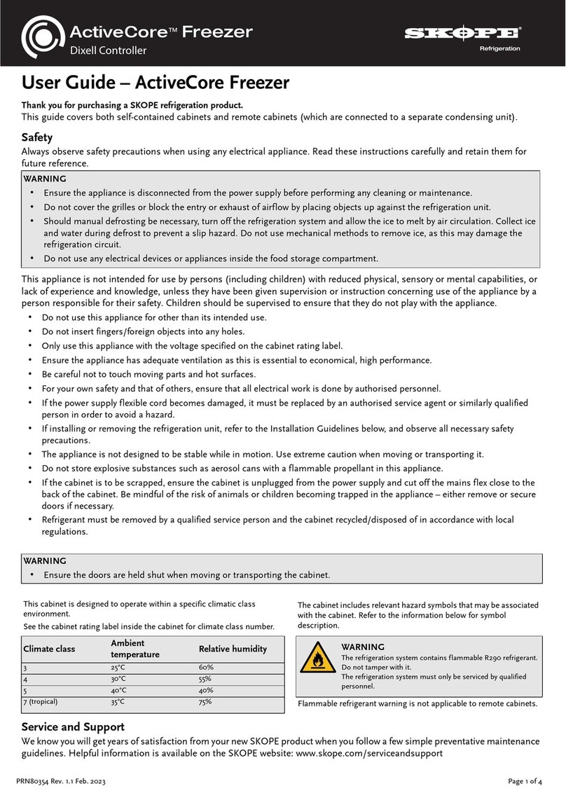
Skope ActiveCore SKFT1500N-A-WG User manual
Skope
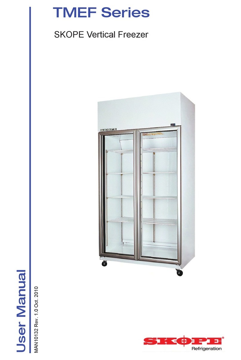
Skope TMEF Series User manual

Skope
Skope PG600VF User manual
Skope
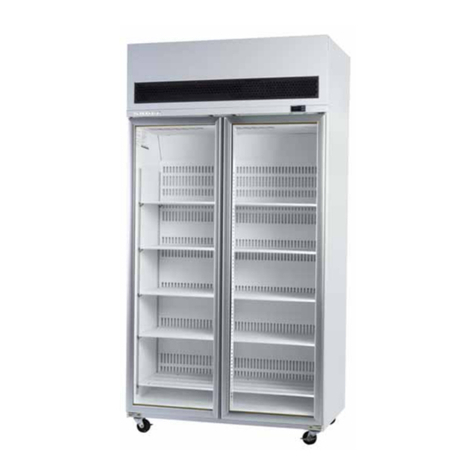
Skope VF Series User manual
Skope
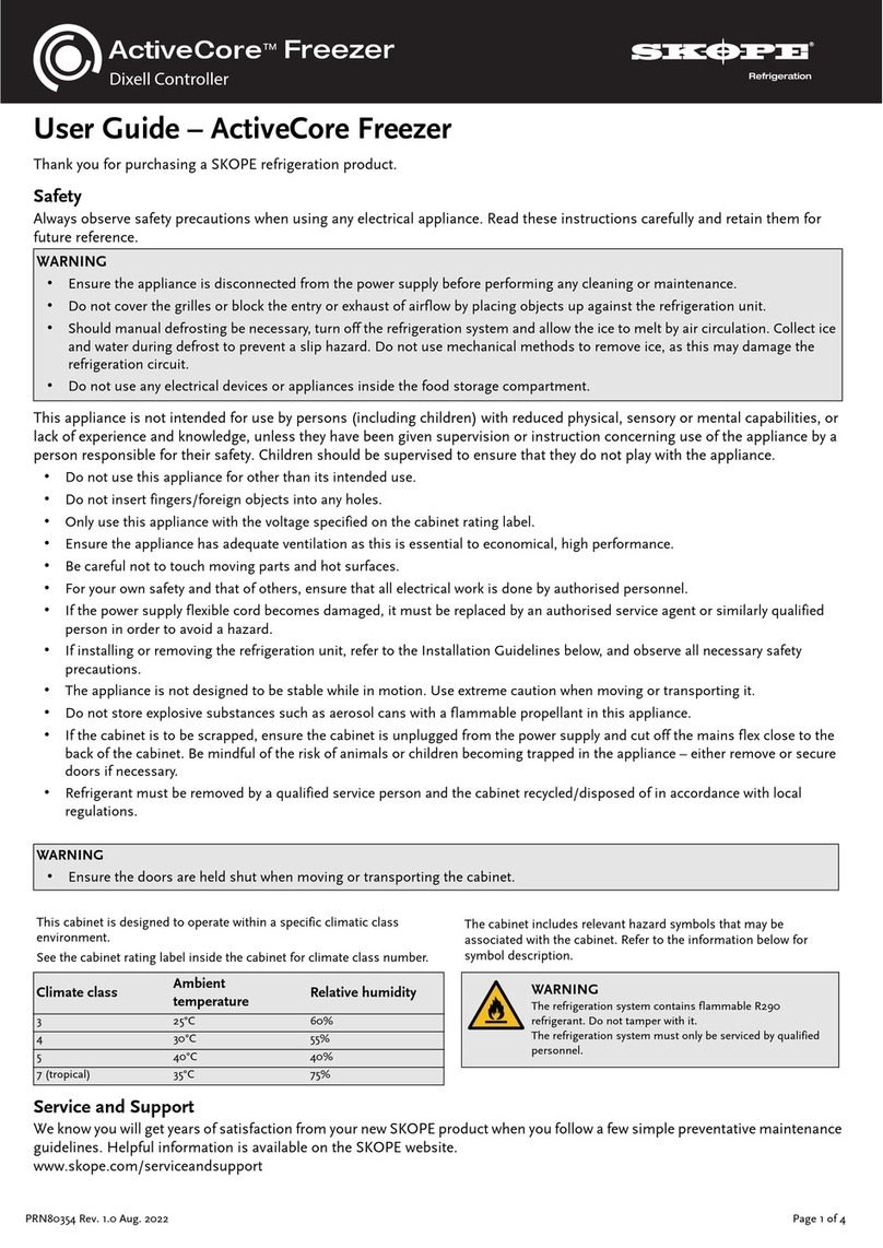
Skope ActiveCore User manual
Skope
Skope Centaur Series User manual
Skope
Skope BC070-CB User manual

