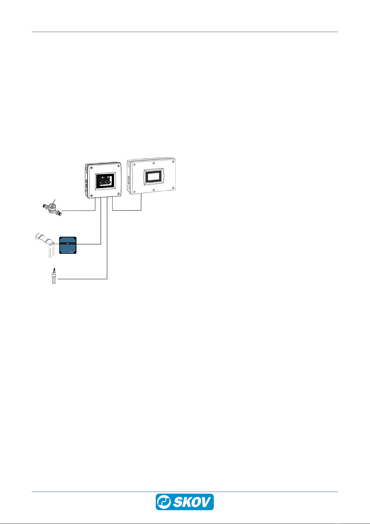
EnglishDeutsch
 logo
Brands
  1. Home
  2. •
  3. Brands
  4. •
  5. Skov
  6. •
  7. Industrial Equipment
  8. •
  9. Skov DOL 100 Manual

Skov DOL 100 Manual

Other manuals for DOL 100

2

This manual suits for next models

4

Other Skov Industrial Equipment manuals

Skov DA 820 Installation instructions manual

Skov

Skov DA 820 Installation instructions manual

Skov DA 820F VFD Manual

Skov

Skov DA 820F VFD Manual

Popular Industrial Equipment manuals by other brands

ABB Unifix AD Instruction handbook

ABB

ABB Unifix AD Instruction handbook

Mark 7 Evolution user manual

Mark 7

Mark 7 Evolution user manual

Husky HyPET Original instructions

Husky

Husky HyPET Original instructions

bora PM-1800 user manual

bora

bora PM-1800 user manual

Grizzly T32428 owner's manual

Grizzly

Grizzly T32428 owner's manual

Siemens 8MF1 Series operating instructions

Siemens

Siemens 8MF1 Series operating instructions

ABB HT610965 Operation manual

ABB

ABB HT610965 Operation manual

ABB SafeLink Installation and operating instructions

ABB

ABB SafeLink Installation and operating instructions

Phoenix PHX-150 user guide

Phoenix

Phoenix PHX-150 user guide

ABB A165-L32 Operation manual

ABB

ABB A165-L32 Operation manual

ABB HT842936 Operation manual

ABB

ABB HT842936 Operation manual

Hermetica 10 Series user manual

Hermetica

Hermetica 10 Series user manual

HORNER OEE Solution manual

HORNER

HORNER OEE Solution manual

Hammerhead HG375 parts manual

Hammerhead

Hammerhead HG375 parts manual

SCHUNK VERO-S NSE-A3 138 Assembly and operating manual

SCHUNK

SCHUNK VERO-S NSE-A3 138 Assembly and operating manual

ABB HT566657 Operation manual

ABB

ABB HT566657 Operation manual

Webasto GSE CAN installation guide

Webasto

Webasto GSE CAN installation guide

ABB HT614003 Operation manual

ABB

ABB HT614003 Operation manual

https://manuals.online logo
https://manuals.online logoBrands
  • About & Mission
  • Contact us
  • Privacy Policy
  • Terms and Conditions

Copyright 2026 Manuals.Online. All Rights Reserved.

DOL 100 digital box
Technical User Guide
604336 • 2023-05-31
DOL 100 digital box
2 Technical User Guide
Product and Documentation Changes
SKOV A/S reserves the right to change this document and the product herein described without further notice.
In case of doubt, please contact SKOV A/S.
The date of change appears from the front and back pages.
Note
• All rights belong to SKOV A/S. No part of this manual may be reproduced in any manner whatsoever without
the expressed written permission of SKOV A/S in each case.
• All reasonable efforts have been made to ensure the accuracy of the information contained in this manual.
Should any mistakes or imprecise information occur in spite of this, SKOV A/S would appreciate being noti-
fied thereof.
• Irrespective of the above, SKOV A/S shall not accept any liability with regard to loss or damage caused or
alleged to be caused by reliance on any information contained herein.
• Copyright by SKOV A/S.
DOL 100 digital box
1 Product description ....................................................................................................................................... 4
2 Product survey ............................................................................................................................................... 5
2.1 Accessories................................................................................................................................ 5
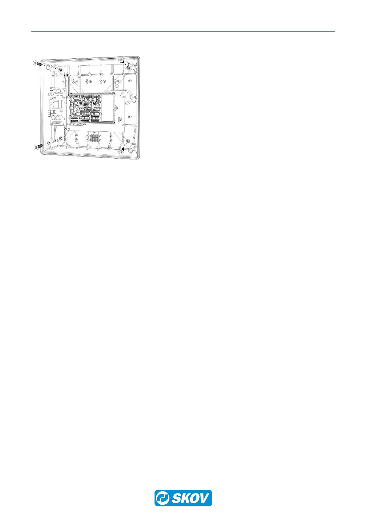
3 Mounting guide............................................................................................................................................... 6
3.1 Recommended tools.................................................................................................................. 6
3.2 Mounting on wall........................................................................................................................ 7
4 Installation guide............................................................................................................................................ 8
4.1 Electrical connection................................................................................................................. 8
4.2 Cable routing.............................................................................................................................. 8
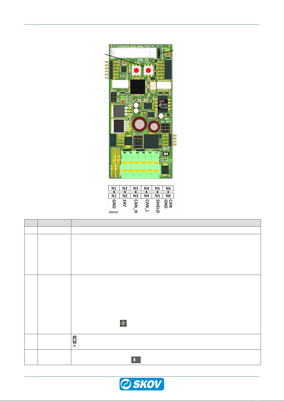
4.3 Nano CAN bus coupler.............................................................................................................. 9
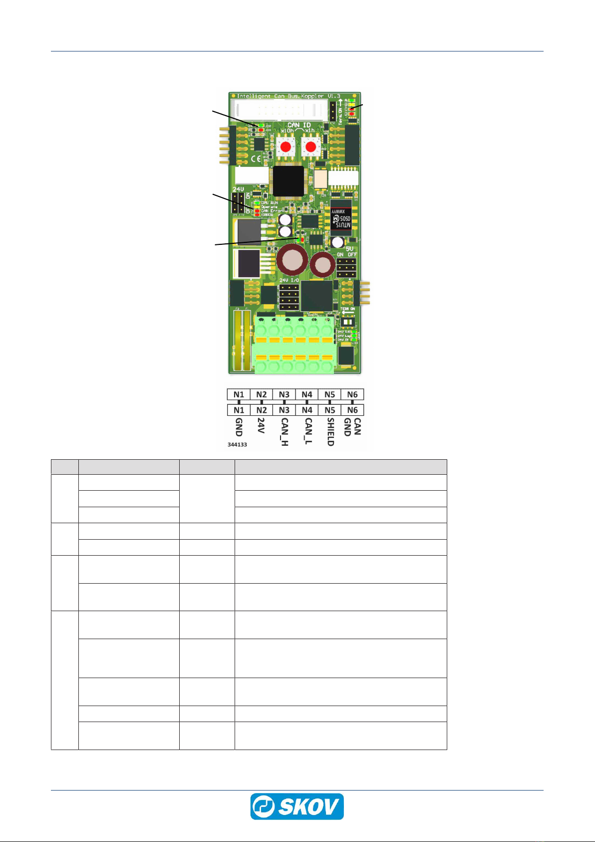
4.3.1 LED indication on the CAN bus coupler..................................................................................... 10
4.4 Nano I/O module digital........................................................................................................... 11
4.5 Connection in DOL 100 ........................................................................................................... 12
4.6 Setting up the DOL 100 in the controller ............................................................................... 13
4.7 Cable Plan................................................................................................................................. 14
4.8 Circuit diagram......................................................................................................................... 15
4.8.1 DOL 100 and water meter.......................................................................................................... 15
4.8.2 DOL 100 and capacitive sensor................................................................................................. 15
4.8.3 DOL 100 and DOL 192 24 V...................................................................................................... 16
4.8.4 DOL 100 and DOL 192 230 V.................................................................................................... 16
5 Cleaning ........................................................................................................................................................ 17
6 Troubleshooting guide ................................................................................................................................ 18
7 Technical data .............................................................................................................................................. 19
Technical User Guide
DOL 100 digital box
4 Technical User Guide
1 Product description
DOL 100 Digital 8I/16I/24I/32I box is used to connect water meter, egg counter, and capacitive sensor to the
CAN bus communication and thereby avoid numerous cables to the climate controller.
The DOL 100 converts the signal into digital signals and transmits them to the controller using CAN bus commu-
nication.
• DOL 100 digital is available in 4 variants:
• Connect up to 8 items to the DOL 100 digital 8I box.
• Connect up to 16 items to the DOL 100 digital 16l box.
• Connect up to 24 items to the DOL 100 digital 24I box.
• Connect up to 32 items to the DOL 100 digital 32I box.
(C)
(B) (A)
(D)
(E)
(A) Controller
(B) Connect up to 32 items to the DOL 100
digital 8l/16l/24I/32I box.
(C) Water meter
(D) Egg counter
(E) Capacitive sensor
DOL 100 digital box
Technical User Guide 5
2 Product survey
130183 DOL 100 digital 8l box
130184 DOL 100 digital 16l box
130191 DOL 100 digital 24l box
130192 DOL 100 digital 32l box
External I/O box for connection of water meter, egg counter, or capacitive
sensor.
The DOL 100 converts the signals into digital signals and transmits them to
the production controller using CAN bus communication.
The standard software/hardware of the BlueControl series supports 13 I/O
modules in total. DOL 100 counts as one module.
0-24 V inputs terminals: 8, 16, 24 or 32.
Is used with the CAN bus module (132245) and a CAN bus cable
(130121-130128).
2.1 Accessories
132245 CAN-bus module
Always use the CAN-bus module when using external CAN bus communi-
cation.
One for each controller.
130121 CAN bus cable 50 m
130125 CAN bus cable 100 m
130126 CAN bus cable 250 m
For indoor use.
Must be used with external units using CAN bus communication.
130123 CAN bus cable UV 50 m
130127 CAN bus cable UV 100 m
130128 CAN bus cable UV 250 m
For outdoor use.
Must be used with external units using CAN bus communication.
DOL 100 digital box
6 Technical User Guide
3 Mounting guide
3.1 Recommended tools
Below follows a list of tools recommended for installation of the DOL 100.
Item Description
Cordless drill
Screwdriver bits
Utility knife
Multimeter
Tape measure
Side cutter
Pointed pliers
Ladder
Screwdriver
Spirit level
DOL 100 digital box
Technical User Guide 7
3.2 Mounting on wall
Mount the DOL 100 digital box on the wall us-
ing 4 screws.
DOL 100 digital box
8 Technical User Guide
4 Installation guide
4.1 Electrical connection
Installation, servicing and troubleshooting of all electrical equipment must be carried out by quali-
fied personnel in compliance with the applicable national and international standard EN 60204-1
and any other EU standards that are applicable in Europe.
The installation of a power supply isolator is required for each motor and power supply to facilitate
voltage-free work on the electrical equipment. The power supply isolator is not included.
4.2 Cable routing
To prevent water from running into the DOL
100 via cables and screwed connections, run
the cables so that water does not gather around
the cable in the gasket of the screwed connec-
tion.
DOL 100 digital box
Technical User Guide 9
4.3 Nano CAN bus coupler
(A)
(A) (A)
(A)
(B)
(D)
(C)
(E)
Item Function Description
(A) Terminals Terminals to I/O modules
(B) N1 GND
N2 +24V
N3 CAN_H
N4 CAN_L
N5 SHIELD
N6 CAN GND
0 V
Power supply +24 VDC (max. 2.1 A)
CAN high (brown CAN bus)
CAN low (white CAN bus)
Shield (braided shield CAN bus)
(green CAN bus)
The terminal can also be used as a looped terminal strip to the next box.
(C) CAN ID CAN bus address (CAN ID). The address switches are used for setting the CAN ID.
The DOL 100 must have a specific CAN ID for the controller to communicate with it. The
address of the individual DOL 100 corresponds to the address in the controller in the
menu Technical | Setup | Installation | I/O Modules | Additional I/O Modules
The address switches
X10 is set to 5 in connection with DOL 100 water and 3 in connection with DOL 100 digi-
tal.
The address switches X01 are set to the displayed number or letter after the figure 5
or 3 in the controller. If change of address, restart DOL 100 for the change to take effect.
(D) TERM ON
Jumper is set to (ON).
(E) TERM ON CAN bus termination. If DOL 100 is the last node in the CAN bus communication, the
jumper must be set to (ON) .
DOL 100 digital box
10 Technical User Guide
4.3.1 LED indication on the CAN bus coupler
(A)
(B) (D)
(C)
(D)
Item Function LED color Description
(A)
24 V IN
Green
ON: 24 V DC power supply OK.
24 V Log ON: 24 V DC Internal OK.
24 V I/O ON: 24 V DC I/O fuse F1 OK.
(B)
Internal CAN bus RX Green ON: receiving data
Internal CAN bus TX Red ON: transmitting data
(C)
External CAN bus
RX
Green ON: receiving data
External CAN bus
TX
Red ON: transmitting data
(D)
CPU RUN Green FLASHES: OK.
OFF: not ready for operation.
Operate Yellow States the CAN bus status
ON: operate
OFF: pre-operate
CAN ERROR Red OFF: CAN bus OK.
FLASHES: CAN bus error.
ERROR Red General error
Boot mode All LED ON (CPU RUN, Operate, CAN ER-
ROR and ERROR