Skylift Drones X8 800 User manual

SKYLIFT Y6 800 USER
GUIDE
SKYLIFT DRONES
SKYLIFT X8 800 USER GUIDE
SKYLIFT DRONES. 38 JUBILEE AVE,
DAWNVIEW,GERMISTON,1401 , SOUTH AFRICA
SKYLIFT X8 800 SERIAL NO: ………………………………………
[Cite your source here.]

1 | P a g e
SKYLIFT X8 800 USER GUIDE
TABLE OF CONTENTS
1.INTRODUCTION ................................................................................................2
1.1 SYSTEM OVERVIEW.............................................................................................2
1.2 AIRCRAFT ( RPA ) OVERVIEW................................................................................2
1.2.1 BATTERY.............................................................................................................2
1.2.2 MOTORS AND PROPELLERS ..............................................................................2
1.2.3 ORIENTATION LED..............................................................................................3
1.2.4 CAMERA MOUNT OPTIONAL ACCESSORY ..........................................................3
1.3 OPERATING PARAMETERS ........................................................................3
1.4. AUTO PILOT SYSTEMS ................................................................................3
2. SETUP ..................................................................................................................3
2.1.1 ASSEMBLY ..........................................................................................................4
2.1.2 BATTERIES .........................................................................................................4
2.1.3 PROPELLERS ......................................................................................................4
2.1.3.1 REPLACEMENT OF PROPELLERS ....................................................................4
3. MAINTENANCE ..................................................................................................4
4. SAFETY ...............................................................................................................5
4.1 LOCATION............................................................................................................5
4.2 ENVIRONMENTAL AWARENESS .............................................................................5
4.3 PILOT TRAINING....................................................................................................5
5. LIST OF ABBREVIATIONS ...................................................................................5

2 | P a g e
SKYLIFT X8 800 USER GUIDE
1. INTRODUCTION
The Skylift X8 800 frame is manufactured by Skylift Drones based in South Africa.. The frame is
manufactured from carbon fiber and composite injection parts . It is a RPA powered by eight motors and 8
propellers. It is a medium sized RPA with a diameter motor to motor of 800 mm. It was designed to lift a
payload of 4 kgs. The frame weighs 3 kgs. This does not include batteries, controller or accessories.
1.1 SYSTEM OVERVIEW
The system includes main center frame with 4 unpluggable pre-assembled arms complete with motors, Esc’s
propellers and plug-in system.
1.2 AIRCRAFT ( RPA ) OVERVIEW
Flight times –up to 30 min
Payload –4 kgs
Diameter –motor to motor –80 cm
Weight ( Excluding battery and payload ) -3100 g
Height –30 cm
Landing Gear Height –27.4 cm
Carbon fiber plates and composite injection moulded parts, stainless steel hardware.
1.2.1 BATTERY
Skylift X8 800 is powered by 2 x 6s 10 000 mah batteries.
That will allow the RPA to fly for up to 30 mins depending on payload, height above sea level, wind
conditions, condition of batteries as well as atmospheric conditions.

3 | P a g e
1.2.2 MOTORS AND PROPELLERS
8 x Tiger Motors and APC propellers . Top Propellers spin anti clockwise . Bottom propellers spin
clockwise.
1.2.3 ORIENTATION LED
Each arm contains an LED for ground to air directional awareness. Back arms are yellow and have yellow
LED’s . Two front arms are black and display blue LED’s.
1.2.4 CAMERA MOUNT OPTIONAL ACCESSORY
There are two ways to mount a camera .
a. 12 mm carbon rods which attach to the top plate . This accommodate DJI Zenmuse type gimbal.
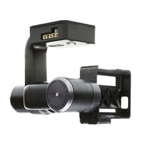
b. Leg clip which allows Skylift surveyor’s gimbal to clip and unclip directly onto leg set.
1.3 OPERATING PARAMETERS
Max flight time
30 mins
Max Altitude
Depending on radio system
Range
Depending on radio system
Max Payload ( excluding batteries )
3 kgs
Max speed
120 km/h
Max wind
50 km/h
Operating temperature
32 º F to 115º F ( 0ºC to 45ºC )
Flight time varies with payload, wind conditions, elevation, temperature,humidity , battery size as well as pilot
skills.
1.4. AUTO PILOT SYSTEMS
Skylift X8 800 frame was designed to accommodate different autopilot systems.

4 | P a g e
2. SETUP
The Skylift framekit consists of the following :
1. Main carbon fiber body
2. Battery straps x 2
3. 4 x assembled arms –with speed controllers and motors . 2 x yellow , 2 x black
4. Landing legs with adjustable skids
5. 4 x APC 15 x 8 E top props
6. 4 x APC 15 x 10 EP bottom props
2.1.1 ASSEMBLY
Remove Skylift X8 800 from its transport package.
Slide Leg set until it clicks into position on center frame.
To release legs press locking lever up and slide legs off.
Insert arms by ensuring cam latch “ 0 “ marking lines up with locking pin on frame. Push arm into frame and
turn cam latch clockwise until it clicks indicating locked position. To unlock the arm turn cam latch anti-
clockwise and pull the arm outwards.
2.1.2 BATTERIES
Maximum capacity of 6s is allowed. We recommend 2 x 6s 10 000 mah for best performance.
Load batteries and secure in place with battery straps.
2.1.3 PROPELLERS
A maximum size of 17 “ propellers can be used on this system.

5 | P a g e
2.1.3.1 REPLACEMENT OF PROPELLERS
We recommend APC 15 x 8E on top motors and APC 15 X 10 EP on bottom motors.
Remove old prop by loosening nut and sliding prop off. Attach new prop as follows :
Top Prop APC 15 x 8 E - Inserting 6 mm spacer at bottom of prop and attach to motor shaft . Place prop
so that the lettering is visible on top. Using size 10 spanner grip motor and tighten nut . Never overtighten as
this will damage the threads.
Bottom prop APC 15 x 10 EP - Insert 6 mm spacer at bottom of prop and attach to motor shaft. Place prop
so that the lettering is visible on top. Using size 10 spanner grip motor and tighten nut. Never overtighten as this
will damage the threads.
3. MAINTENANCE
Replace batteries when capacity starts to drop or they start swelling.
Check motors before and after each flight for noise as well as excessive heat. Motors should not exceed
50 degrees Celsius after a flight.
Check battery connections are clean and free from carbon buildup. Replace plugs after 100 flights.
Replace bearing sets on motors after 50 hours or when they start to sound noisy. We recommend it to be
done by qualified person. https://www.youtube.com/watch?v=z4NvWqkvx3k
Replacing an arm. Remove arm by turning cam latch counterclockwise and pulling arm out once it is
released from locked position.
Inserting new arm. Ensure cam latch “ 0 “ marking lines up with locking pin on frame. Push arm and turn
cam latch until it clicks indicating locked position.
Replacing props . Remove old prop by loosening nut and sliding prop off. Attach new prop as follows : Top
prop of Skylift Y600 - 15 x 8E . Inserting 6 mm spacer at bottom of prop and attach to motor shaft with size
of prop visible at top. That will be the correct position for the prop. Using size 10 spanner grip motor and
tighten nut just enough so that prop does not turn. Never overtighten. Bottom prop of Skylift Y600 –15 x
10 EP . Insert 6 mm spacer at bottom of prop and attach to motor shaft with size of prop visible at top end.
Looking down you must be able to see the size of the prop . That is the correct position of the prop. Using
size 10 spanner grip motor and tighten nut just enough that prop does not turn. Never overtighten.
Balance props regularly.
Replacing skid set . Press down on latch at bottom of frame to release the skid set. Center the carbon rod
by sliding it to center .Slide new skid set into latch at bottom of the frame . Once you hear the click it is
securely in place.
Replacing carbon fiber plates of frame should be done by a qualified person.
Check transmitter radio battery and replace when capacity is low.
4. SAFETY
Do not fly when under the influence of drugs or alcohol. Once the motors of the RPA is turning and the
propellers are spinning maintain a safe distance as the spinning propellers can cause serious injury.
4.1 LOCATION
Comply with safety regulations and restrictions in the country you are operating the RPA in.
All countries have flight restrictions around airports. Ensure you are familiar with these restrictions.
When flying in areas with potential hazards , maintain 50 m from people, vehicles or structures.
4.2 ENVIRONMENTAL AWARENESS
Check weather forecast before flying.
Do not fly in rainy weather or high wind conditions.
Study the terrain you are about to fly and determine safe landing spaces away from water, people , power
lines or obstructions in the event of an emergency procedure.
Throughout your flight be prepared to recover your RPA manually in the event of an emergency.

6 | P a g e
4.3 PILOT TRAINING
For first time RPA Pilots we recommend they learn the controls of the RPA and the flying of the RPA by
Means of a simulator program on the computer.
Pilots who wish to fly RPAS commercially need to do a licence course for a commercial qualification.
5. LIST OF ABBREVIATIONS
RPA –Remote Pilot Aircraft
RPAS –Remote Pilot Aircraft System
Table of contents
