SkylinkHome Houselink 318STR User manual
1.INTRODUCTION
Houselink®Lighting &Garage
DoorRemote Model 318STR
2.INSTALLATIONOFGARAGEDOORRECEIVER
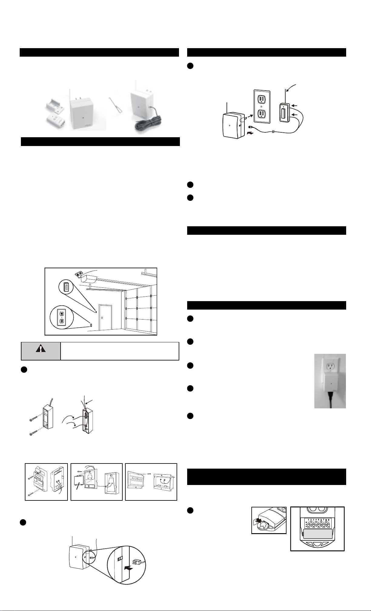
In this package, you will find a keychain transmitter with 12V alkaline
battery, a wireless switch receiver, a garage door receiver, a red /
black wire, a mounting bracket and a clip.
Clip
The following instructions will show you how to install the receiver.
After installing, the keychain transmitter (already programmed to
the receiver) can be used to operate your garage door opener.
You need to locate 2 things inside your garage to install the
receiver:
1) the wall-mounted door control;
2) an electrical outlet, select an electrical outlet different from
the one already connected to the power cord of the garage
door opener to reduce the chance of interference. The
further distance between the receiver and the garage door
opener, the less interference between 2 devices.
Note: The length of the red/black wire is 15ft, so the receiver must be
pluggedinto anelectrical outletthat iswithin 15ftof thewall mounted
door control. If there is no electrical outlet within 15ft of the wall
mounteddoor control,an extensioncord canbe usedfor temporary
installation. Longer wire is available, please contact our customer
servicefor furtherinformation.
1Remove the wall-mounted door control from the wall by
removing the screws. Connect the stripped ends of the Red/
Black wire to the 2 terminals (2 screws) on the back of the
wall mounted door control. (Polarity does not matter.)
Unplug the power cord of your garage door opener before
installation to ensure power is not connected.
WallMounted
DoorControl
Electrical
Outlet
Plug the receiver into an electrical outlet inside the garage.
The red light on the receiver should be on after being plugged
into an electrical outlet.
Re-connect the power cord of the Garage Door Opener.
The Left button on the transmitter has been programmed to
operate the garage door receiver. Activate this button will
trigger the receiver therefore opens the garage door.
2.INSTALLATIONOFGARAGEDOOR RECEIVER(CONT)
3
4
5
WARNING
Removepowercordofgarage
dooropenerbeforeinstallation.
Red /
Blackwire
Note:Thereshouldbe another
pairofwires connected tothe2
terminalsalready.Donotremove/
disconnect these existing wires.
Note:If you see no screwsmounting the wall mounted doorcontrol,
thescrews are probablyunder-neath thefront cover. Removethe
front cover by pressing onto the tabs on top of the cover.
Remove front
cover first
3.TROUBLESHOOTING
Q: Door opener does not react after pressing the button on the transmitter ?
A: - Ensure when the button on the transmitter is pressed, the red light on the trans-
mitter comes on. Otherwise, check if the battery is inserted properly.
- The left button on the transmitter should be pressed, not the right button
- If the red light on the receiver flashes when you press the left button on the
transmitter, but the door opener does not respond, please ensure the red/black
wire is successfully connected from the receiver to the wall mounted door control.
- Ensure the wires that are previously connected to the wall mounted
door control are not loose.
- Ensure the code setting on the transmitter is the same as the receiver. Refer
to section 5 to check the code setting.
Existing
wires
RED/BLACK WIRE
RECEIVER
Existingwires connected
to garage door opener.
(Do not remove)
Different wall-mounted door controls
Note: Alternative wiring options are available, the receiver can be
connected directly to the opener’s motor. Please contact customer
service for further information regarding alternative wiring options.
Mounting
Bracket
Keychain
Transmitter
(Batteryinside)
Plug in the connector end of the Red/Black wire to the 318R
receiver. Note the orientation of the male & female connector.
2
WirelessSwitch
Receiver Garage Door
Receiver
Red/Black Wire
4. INSTALLATIONOFWIRELESS SWITCH RECEIVER
Plug the receiver into a powered, 120VAC electrical outlet inside
your house. (Note: This receiver is designed to be used indoor
only. Do not use this receiver in an outdoor environment.)
Once the receiver is plugged into an electrical outlet, the red
LED on the front of the unit will be “on” indicating the unit is in
standby mode.
Plug in the light fixture or small appliance
that you would like to control into the
receiver, as shown.
If there is a power switch on the plugged
in light fixture or small appliance, please
turn it on. The receiver is ready to be
activated.
The right button on the transmitter has been programmed to
operate the wireless switch receiver, pressing the right button
will turn on the plugged in device and the red LED on the front
will flash. (Caution: When the red LED on the unit is flashing,
that means output outlet is powered. Do not disconnect / con-
nect devices from / to the receiver’s outlet when the red LED is
flashing.)
1
2
3
4
5
5.CHANGETHEOPERATIONCODEFOR
BOTHTRANSMITTERANDRECEIVERS
Follow the instructions below if you want to change the operation
code.
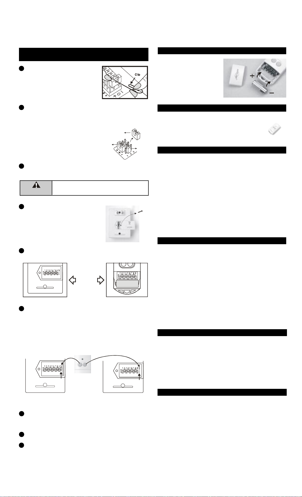
Pryoffthe battery
cover of the trans-
mitter with a coin,
as shown.
You will see 9 connectors labeled
from “1” to “9”, as shown. (the
connectors setting may not be the
same as shown.)
1
BATTERY
BATTERY
If, within one year from date of purchase, this product should become defective
(except battery), due to faulty workmanship or materials, it will be repaired or
replaced, without charge. Proof of purchase and a Return Authorization are required.
10.WARRANTY
On the garage door receiver
and wireless switch receiver,
remove the screw that holds
the connector covers, and
remove the covers.
You will see 10 connectors. For connectors “1” to “9”, the
settings must match with those of the transmitter.
Connector 10 on the receiver should be set to “+” if it is con-
trolled by the transmitter’s left button , connector 10 on the
receiver should be removed if it is controlled by the trans-
mitter’s right button. Example, if the left button is used to
control the garage door receiver, connector 10 on the garage
door receiver should be set to ”+”. If the right button is used to
control the wireless switch receiver, connector 10 on the
wireless switch receiver should be removed.
5.CHANGE THEOPERATIONCODEFORBOTH
TRANSMITTERANDRECEIVERS (CONT)
Connector 10 “Removed”
Connector 10 set to “+” TRANSMITTER
You can add as many additional transmitters as you want to
control the same receiver. Simply set the same operation code
on all transmitters with the same code setting on the receiver.
Houselink®offers Keychain Transmitter Model 318TN to work
with your receiver. For more information, please visit our website
at www.skylinkhome.com or contact us.
7.ADDITIONALTRANSMITTER
RISKOFELECTRICALSHOCK. FORINDOORUSEONLY.
CAUTION:NOTFORUSEWITHDIMMER.
CAUTION:DISCONNECTPOWERBEFORECODECHANGING.
REPLACECOVERAFTERCODECHANGING.
8.CAUTION
9.FCC
Thisdevice complieswith Part15 ofthe FCCRules. Operationis subjectto thefollowing twoconditions:
(1)Thisdevicemaynot causeharmfulinterference,and(2)Thisdevice mustacceptanyinterference
received,includinginterference thatmaycauseundesiredoperation.
WARNING:
Changesormodificationstothis unitnotexpresslyapprovedby thepartyresponsibleforcompliance could
voidtheuser’s authoritytooperate theequipment.
NOTE:
Thisequipment hasbeentestedandfoundtocomply withthe limitsforaClassBdigitaldevice,pursuant
toPart 15of theFCC Rules.Theselimitsaredesignedto providereasonable protectionagainstharmful
interferencein aresidentialinstallation.Thisequipment generates,uses andcanradiateradiofrequency
energyand, ifnot installedand usedin accordancewith theinstructions, maycause harmfulinterference
toradiocommunications.
However,thereisnoguaranteethatinterferencewillnotoccurinaparticular installation.Ifthisequipmentdoes
causeharmfulinterferencetoradioortelevisionreception,which canbedeterminedbyturningtheequipment
offandon,theuserisencouraged to trytocorrectthe interference byoneormore of thefollowingmeasures:
-Reorient orrelocatethe receivingantenna.
-Increasetheseparationbetween theequipment andreceiver.
-Connect theequipment intoanoutletonacircuitdifferent fromthat towhich thereceiver isconnected.
-Consult thedealer oranexperienced radio/TVtechnician forhelp.
5
6
7
WIRELESS SWITCH RECEIVER
SW-318R
GARAGEDOOR RECEIVER
318R
Connectors
1 to 9 are
thesame.
8Put the cover and screw back onto the receivers. Install the
garage door receiver and wireless switch receicer based on
previous illustrations on sections 2 and 4.
Put the battery cover back onto the transmitter.
Press the left button on the transmitter to operate the garage
door receiver or press the right button to turn on/off the light
fixture/small appliance.
9
12 volt alkaline battery (size 23A)
(included).
It is time to change the battery
when the red LED on the trans-
mitter does not turn on when
either button is pressed.
6.BATTERY
11. CUSTOMERSERVICE
CUSTOMER SERVICE
17 Sheard Avenue, Brampton, Ontario, Canada L6Y 1J3
http://www.skylinkhome.com
P/N.101A231Rev.0
USPatent.D380895
©2003SKYLINK GROUP
If you would like to order Skylink’s products or have difficulty getting them to work,
please :
1. visit our FAQ website at www.skylinkhome.com, or
3. call our toll free at 1-800-304-1187 from Monday to Friday, 9 am to 5 pm EST.
Fax +800 286-1320
10
MODEL:318R
MaximumRating:
Input : 120VAC 60Hz 2W
MODEL:SW-318R
MaximumRating:
Input : 120VAC 60Hz
Resistive load : 8A (960W)
Incandescent : 300 watts
Motor Load : 1/3 HP
If the connector is placed on the top and middle posts, that
column is set on “ + ” . If the connector is placed on the middle and
bottom posts, that column is set on “ - ”. If the connector is
removed completely, (not placed on any posts), it is set to “ 0 ”.
(see diagram for examples of how to
set a column to the three different
positions). When removing a con-
nector to set a column to “ 0 ”, save
the connector in case you change
the code at a later date.
After setting up the code connectors on the transmitter, you
are ready to set the same code on the receivers.
Remove the receiver from the electrical outlet before
changing the code.
3
4
WARNING
‘+’ ‘-’
‘0’
You can randomly remove some
connectors, leaving some in place.
A connector can be removed with
the clip, as shown.
2
Popular Garage Door Opener manuals by other brands


ForceDoor
ForceDoor FS 600 Installation instructions and user guide

4Ddoors
4Ddoors SOLAR GA201 Instructions for fitting, operating and maintenance

Raynor
Raynor Navigator 2245RGD owner's manual

EINHELL
EINHELL TAF 362 Mounting and operating instructions

Automatismos Pujol
Automatismos Pujol Marathon Pro III manual

Chamberlain
Chamberlain 8557 manual


